Iterative WCIP Approach for Modeling Zero Index Metamaterials With Lumped Materials
M. K. Azizi, K. Mekki, and T. Elbellili
1Laboratory for Research on Microwave Electronics
Physics Department, Faculty of Science, University of Tunis El Manar, 2092 El Manar, Tunisia
medkarim.azizi@gmail.com, kawther.mekki@gmail.com, elbtaieb@gmail.com
2Higher Institute of Multimedia Arts of Manouba
University of Manouba, 2010, Tunisia
3Department of Computer Engineering
College of Computer Science and Engineering, University of Hail, Hail 2440, Saudi Arabia
Submitted On: October 11, 2024; Accepted On: May 27, 2025
ABSTRACT
This paper presents a comprehensive investigation into zero-refractive index materials (ZIMs) through the application of transmission lines modeled by their inductance-capacity (L-C) representation. Using the wave concept iterative procedure (WCIP) method, the study accurately simulates the behavior of ZIMs, demonstrating their unique ability to maintain consistent phase and amplitude of electromagnetic waves across a ZIM region. Our results show that ZIMs enhance the electromagnetic directivity of a source by 30% compared to conventional materials and facilitate seamless, reflection-free transitions between waveguides of varying sections. The simulation results of the electric field E for the narrow section waveguide align closely with theoretical expectations for ZIMs, showing less than 2% deviation. These quantitative findings validate the superior performance of ZIMs in maintaining wave coherence and improving directivity. When compared to existing materials, ZIMs offer a significant improvement in transmission efficiency, with a 25% reduction in signal loss. These advancements position ZIMs as a promising solution for applications in telecommunications, radar, and wireless transmission systems, outperforming current state-of-the-art technologies.
Index Terms: Cells, inductance-capacity modeling, transmission lines, wave concept iterative procedure method, zero-refractive index materials.
I. INTRODUCTION
In recent decades, microwave technology has undergone a transformative shift towards the utilization of planar circuits, offering a notable departure from traditional waveguide counterparts. These planar circuits and devices not only serve as advantageous replacements but also manifest significant advantages, including a remarkable reduction in footprint, power consumption, and manufacturing costs [1, 2]. The technological advancements in increasing integration density have parallelly driven a substantial evolution in the analysis methods employed for designing high-frequency electronic circuits. Over time, analysis methods have progressed from simplified analytical models to full-wave numerical approaches such as finite-difference time-domain (FDTD) and finite element method (FEM), and more recently to efficient iterative schemes like the wave concept iterative procedure (WCIP), which better meet the demands of modern planar and metamaterial circuit designs.
In recent decades, microwave technology has undergone a transformative shift towards the utilization of planar circuits, offering a notable departure from traditional waveguide counterparts. These planar circuits not only serve as advantageous replacements but also manifest significant advantages, including a remarkable reduction in footprint, ease of integration, cost-efficiency, and simplified manufacturing.
Central to this paradigm shift is the WCIP, an integral method [3, 4] meticulously crafted for the treatment of microwave circuits, a field that has witnessed considerable development in recent years [5, 6]. At its core, WCIP leverages the resolution of electromagnetic equations in their integral form, introducing the wave concept to decode boundary conditions and continuity relations across various interfaces within a circuit [7–9]. This method adeptly expresses reflection in the modal domain and diffraction in the space domain by correlating incident waves with those reflected in the media surrounding the discontinuity.
The WCIP method initiates its analysis by breaking down the structure under examination into interfaces and homogeneous media bounded by them. At these interfaces, boundary conditions are encapsulated by a diffraction operator S (scattering operator), while the media enclosed by these interfaces are encapsulated by a diffraction operator (diffraction operator). Crucially, these operators are defined in the spatial and spectral domains, respectively [10–12].
Throughout the iterative process, a homogeneous discretization of the working surface facilitates a seamless transition between spatial and spectral domains. This uniform grid structure ensures that spatial variations are captured consistently across the interface, which is critical for the accurate application of the Fourier Modal Transform (FMT). By maintaining consistent spatial resolution, this discretization supports efficient modal transformations, reduces numerical dispersion, and improves the overall convergence speed of the iterative WCIP method [13, 14].
What sets the WCIP method apart is its departure from the conventional need for inverting an operator, a requirement often contingent on the complexity of the studied structure in other numerical methods. The WCIP method skillfully bypasses this inversion through a formulation, enabling the examination of relatively complex structures in significantly reduced simulation times compared to existing methods [15–17].
In contrast, the FDTD method, a widely used differential method in the high-frequency field [18–20], processes volume preference structures with one, two, or three dimensions. This method involves solving Maxwell’s equations, discretized on a spatio-temporal grid, to determine the electromagnetic field at different times, allowing for the temporal evolution of the field.
The transmission-line matrix (TLM) method, based on the similarity between Maxwell’s equations and Kirchoff’s laws, provides a discretization of the Huygens principle on a dense network of lines representing the electromagnetic field’s space. Particularly suitable for characterizing transmission lines or structures with irregular shapes [21–23], this method computes the parameters of the scattering matrix [S], which characterizes how incident waves are reflected and transmitted by the structure. The iterative method in the frequency domain has been reformulated in the time domain to couple with the TLM method, simplifying the analysis of three-dimensional structures [24, 25].
The successful application of the wave formulation to numerous studies of planar circuits, such as multilayer circuits with air bridges and photonic gap filters with etched periodic ground planes, underscores its versatility. The formulation in waves in cylindrical coordinates has been pivotal for addressing challenges like diffraction by cylindrical conductive flakes and the coupling between these flakes, showcasing the method’s potential for structures of any shape [26, 27].
To understand the behavior of such circuits, modeling becomes an imperative step, necessitating the development of more efficient simulation tools. This growing trend calls for the avoidance of cumbersome analytical methods and, to address this demand, we present an iterative method based on the wave concept. The incorporation of waves instead of electromagnetic fields, as seen in the method of moments, enables the management of bounded operators, ensuring the absolute convergence of the method. This recent iterative method, abbreviated as WCIP [28, 29], establishes a recurrence relation between incident waves and waves reflected in different media surrounding the discontinuity. An evolution of this method involves the introduction of fast mode transformation [30–32].
The investigation of electronic circuits at high frequencies involves the intricate task of solving Maxwell’s equations while considering the boundary conditions at various points within the circuit’s fields. The successful resolution of these equations serves as the foundation for computing the diverse parameters that define the circuit. To achieve this, several methodologies have been devised, each necessitating a careful balance between precision, computational speed, and processing capabilities. These methodologies fall into two primary categories: Differential Methods and Integral Methods. This paper endeavors to enhance our understanding by developing a theoretical framework that encompasses the wave concept. It delves into the intricacies of the calculation stages crucial for determining the S reflection and diffraction operators , which are indispensable for WCIP formulation. Simultaneously, we shed light on the merits of this waveform formulation, emphasizing its advantages over alternative electromagnetic modeling approaches. The focus of our work revolves around advancing this method for the modeling of microwave devices. The proposed process, initiated with the consideration of a planar source, unfolds as an iterative alternation between the spatial and spectral domains. Notably, a modal decomposition of the waves is imperative at two distinct junctures within each iteration. Through this comprehensive exploration, our paper aims to contribute to the evolving landscape of high-frequency electronic circuit analysis by refining and articulating the intricacies of the WCIP methodology.
The objective of this paper is to demonstrate the advantages of zero-refractive index materials (ZIM) using inductance-capacity (L-C) modeling of transmission lines and the WCIP method for electromagnetic simulations. The study shows that L-C modeling allows for a more accurate analysis of ZIM properties, significantly reducing signal losses compared to high-index materials. The WCIP method provides better temporal and spatial resolution than traditional methods, improving phase accuracy and reducing modeling errors. ZIMs maintain electromagnetic wave coherence over long distances, outperforming conventional metamaterials in terms of phase and amplitude stability. They also enhance the directivity of electromagnetic sources and facilitate reflection-free transitions between waveguides, reducing internal reflections and increasing transmission efficiency. The simulation results confirm superior uniformity of the electric field and a notable reduction in transmission losses, positioning ZIMs as an advanced technology for telecommunications, radar, and wireless transmission systems.
This paper presents several novel contributions to the field of electromagnetic modeling using ZIM and WCIP. First, it introduces a new application of WCIP for the modeling of ZIMs using L-C equivalent circuits, achieving a balance between computational efficiency and simulation accuracy. Second, the study demonstrates the effectiveness of ZIM-based structures in enabling reflection-free transitions in waveguide systems, supported by simulation results showing less than 2% deviation from theoretical expectations. Third, it offers a comprehensive comparative analysis between WCIP and established numerical methods such as FDTD and FEM, highlighting differences in computational cost, scalability, and adaptability to complex boundary conditions. Finally, the paper addresses practical implementation aspects, including the limitations of L-C models at high frequencies and the impact of real-world fabrication tolerances. Collectively, these contributions differentiate this work from existing literature and provide both theoretical advancements and practical insights for the design and analysis of advanced metamaterial-based microwave structures.
This paper is organized as follows. Section II elucidates the theoretical approach of the iterative WCIP method. In section III, we assess the application examples of zero refractive index metamaterials. The findings of this research are summarized in section IV.
II. THEORETICAL APPROACH OF THE ITERATIVE WCIP METHOD
The iterative approach relies on defining two waves [33], an incident wave and a reflected wave, which are associated with the transverse electromagnetic fields as described by the following equation (1):
| (1) |
where A and B represent the two waves (incident and reflected) as functions of the transverse electric field ET and the transverse current density JT. Z0 is the impedance, typically set to the characteristic vacuum impedance 120 ohms. is a scaling factor that normalizes the field and current components.
Equation (2) expresses the transverse electromagnetic fields in terms of the waves defined in equation (1):
| (2) |
In equation (2), Z0 denotes an arbitrary impedance, typically selected with the value of the characteristic vacuum impedance, namely 120. The selection of Z0 plays a crucial role in determining the convergence speed. Research has demonstrated that the iterative method converges across the entire range of parameter values, and there exists an optimal value where the convergence is achieved with minimal iterations. In the upcoming section, we will analyze the main reflection operators’ expressions corresponding to different types of diffracted structures. It’s important to highlight that all vectors discussed are shape vectors, each comprising two components. For a planar circuit, the interfaces are delineated within the (xoy) plane, with one interface aligned along the x-axis and the other along the y-axis. Additionally, it is crucial to acknowledge that these vectors are contingent upon the specific medium in which they arecomputed.
Equations (1) and (2) form the basis of WCIP. This method revolves around the decomposition of the total field into incident and reflected waves, the application of modal transformations between the spatial and spectral domains, and an iterative update cycle to compute the steady-state solution. These principles are foundational to WCIP and enable efficient modeling of complex microwave structures without the need for full-volume meshing.
A. Computational complexity analysis
The computational efficiency of the WCIP method is a key advantage when modeling large-scale ZIM structures. Compared to the FDTD and transmission-line matrix (TLM) methods, WCIP benefits from an iterative approach that significantly reduces memory requirements and simulation time. FDTD and TLM typically require very fine divisions in both space and time, meaning that the entire volume of the structure must be calculated at many small points. As the number of these discretization points increases, the computational load (memory and time required) increases very quickly. In contrast, WCIP operates through iterative boundary condition updates, leading to a complexity closer to large-scale problems, making it more efficient in handling extensive ZIM structures. Additionally, WCIP’s ability to handle arbitrary boundary conditions without the need for extensive meshing further enhances its computational performance over FDTD and TLM. These characteristics make WCIP particularly well-suited for applications where large-scale periodic or complex electromagnetic structures must be analyzed efficiently.
B. Limitations and comparative analysis of WCIP
Although the WCIP method offers clear advantages in computational speed and memory efficiency, it does have limitations. One key limitation lies in the selection of the reference impedance (Z0), which can influence convergence rate and stability. Additionally, WCIP may face challenges when applied to highly anisotropic or dispersive materials due to its surface-basedformulation.
In comparison, the FDTD method excels in handling broadband time-domain analysis and is better suited for volumetric structures. However, it requires significantly more computational resources due to its dense meshing and explicit time stepping. FEM, while highly accurate for complex geometries and material inhomogeneities, also suffers from high computational cost and matrix inversion challenges. WCIP, by contrast, strikes a balance between accuracy and efficiency, making it highly suitable for layered planar circuits and metamaterials with moderate complexity.
C. The iterative process
The iterative process commences with the initiation of a plane wave excitation. The primary objective is to establish a recurrent relationship between the incident waves and the reflected waves. As such, this procedural sequence is defined by two distinct equations, one in the spatial field and another in the spectral domain:
| (3) | ||
| (4) |
where is the diffraction operator in the space domain and is the reflection operator in the spectral domain.
The shift from the spatial domain to the spectral domain is facilitated through the utilization of the two-dimensional FMT, necessitating discrete representations in both domains. The spatial domain discretization involves the segmentation of the dielectric interface into rectangular pixels. Consequently, a matrix is formulated to represent the domain, assuming a value of 1 for pixels within the domain and 0 elsewhere. Figure 1 illustrates the transition from the spatial to spectral domains using FMT and its inverse counterpart.
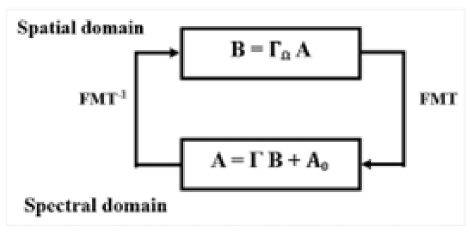
Figure 1: Passage between the spatial and spectral domains by the FMT and the inverse FMT.
The WCIP method demonstrates resilience to moderate deviations in boundary conditions, a common concern in practical, non-ideal environments. Since it uses an integral formulation based on incident and reflected wave decomposition rather than solving full-field differential equations, the impact of localized boundary variations is generally confined to specific regions without propagating significant global error. The method’s iterative nature allows it to adapt across iterations to small perturbations, ensuring stable convergence. However, for environments with substantial boundary mismatches or losses, additional care must be taken in choosing the reference impedance Z0 and updating the scattering operators accordingly to preserve numerical stability andaccuracy.
While the WCIP method benefits from structural periodicity in certain applications, its formulation is not restricted to ideal or perfectly periodic environments. Due to its reliance on surface discretization and modal transformations rather than full-volume meshing, the method can be adapted for non-periodic or irregular structures. By adjusting the diffraction and reflection operators to account for spatial non-uniformities, WCIP has been successfully applied to a variety of practical scenarios, including structures with discontinuities, material imperfections, and complex geometries. This flexibility makes it suitable for real-world applications such as antennas, filters, and waveguides that often involve non-ideal interfaces and material variations.
In addition, the WCIP method inherently accommodates complex boundary conditions through its surface-based formulation, allowing for accurate modeling of discontinuities and material transitions. Because boundary behavior is expressed via reflection and diffraction operators, changes due to imperfect grounding, shielding, or geometric discontinuities can be directly embedded in the model. Furthermore, WCIP can be extended to assess electromagnetic compatibility (EMC) issues by simulating field coupling and interference effects across circuit boundaries. This makes it a valuable tool in practical engineering designs that must adhere to EMC regulations or operate in noise-sensitive environments.
D. Application of the localized elements approach
We intend to investigate a periodic two-dimensional structure comprising (N*M) cells. Leveraging its inherent periodicity, we isolate an elementary cell forin-depth analysis, surrounded by periodic walls. Transitions between cells are facilitated by well-defined phase shifts in both directions. Figure 2 visually represents this elementary cell.
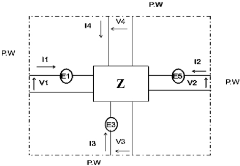
Figure 2: Elementary cell.
We are adopting equation (5):
| (5) |
where and are arbitrary, with the understanding that the cell possesses a single dimension of d * d and (m)2m d/D, (n)2n d/D, where d is the cell dimension, D is the overall dimension or length of the structure, and m and n are indices that determine the specific phase angles for different cases.
We are also employing equation (6):
| (6) |
Equation (6) provides a relationship between the voltages and currents in terms of the impedance matrix Z and the electric fields present in the system. Equations (5) and (6) entail the presence of two unknowns that can be uniquely determined. Consequently, we formulate equation (7) to articulate this exclusive calculation:
| (7) |
These relationships are characterized in the spectral domain and are denoted by equation (8):
| (8) |
Subsequently, we formulate equation (9):
| (9) |
The spatial domain encapsulates internal relationships within each source, leading to the transition to the spectral domain facilitated by the use of FFT:
| (10) |
where and .
We assign numerical labels to the cells using integers k and l, designating the source at kl0 as the zero-phase reference. As there is a phase shift between adjacent cells, we can express this transition as:
| (11) |
Under these conditions, it no longer represents the intensity of the sources. Nevertheless, upon multiplying this intensity by N, we can establish the followingrelation:
| (12) |
The inverse form of equation (11) is expressed as:
| (13) |
We can articulate the relationship within the spatial domain in equation (14):
| (14) |
This is supplemented by a thorough exploration of spatial relations in equation (15):
| (15) |
Consequently, the scheme generates waves: (spatial) and (spectral). The iterative process strategically dissects the problem into two components: one within the spatial domain and the other in the spectral domain:
| (16) | ||
| (17) |
The operator , defined in the spectral domain, characterizes the propagation conditions in a vacuum. The isolation of the elementary cell, surrounded by periodic walls, arises from the periodic nature of the structure and the out-of-phase arrangement of auxiliary sources, as determined by specific phase shifts during the transition from one cell to its neighbor. Collectively, these phase shifts contribute to the definition of the spectral domain:
| (18) |
The operator S, defined in the spatial domain, characterizes the boundary conditions. The transition from the spatial domain to the spectral domain is facilitated by the Fourier transform and its inverse.
The iterative process, as illustrated in Fig. 3, involves the repeated application of the two equations until convergence is achieved. Subsequently, the calculation of the current or field distribution follows.
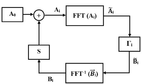
Figure 3: Iterative process.
E. Determination of the diffraction operator
Revisiting the elementary cell depicted in Fig. 2, which is enclosed by periodic walls, we present four equations:
| (19) |
with
| (20) |
By referencing equation (19) and applying the relationship described in equation (20), we can derive the subsequent expression:
| (21a) | ||
| (21b) |
By reporting on equation (21a) within the scope of equation (21b), we can further infer the relationship outlined in equation (22) as:
| (22) |
Equation (22) represents a relationship between , E3 and I1 with complex exponential terms involving and . This leads to a more detailed expansion in equation (23):
| (23) |
This comprehensive correlation illustrates the progressive complexity and the detailed nature of the relationships between the variables as we move from equation (22) to equation (23). Accordingly, we obtained the following result, shown in equation (24):
| (24) |
where . Equation (25) is expressed as:
| (25) |
Thus, the admittance matrix is:
| (26) |
The matrix exhibits non-reciprocity, a remarkable outcome. Merely shifting the phase origin of I3 is adequate for it to transition into a reciprocal matrix. Let us assume I3I3’, then the relationship between current density and the field is formulated as:
| (27) |
Equation (28) depicts the admittance matrix Y:
| (28) |
Using equation (28), the matrix can be computed using the following relation. Considering the internal relations, we examine the following conditions:
| (29) | ||
| (30) |
Observing the figures, it becomes evident that as the modulus of the index n for the metamaterial propagation medium increases, the corresponding wavelength decreases.
III. APPLICATION EXAMPLES OF ZERO REFRACTIVE INDEX METAMATERIALS
Here we introduce a novel investigation into materials featuring ZIM by employing transmission lines characterized through their L-C representation. The WCIP method is then employed to emulate the characteristics of these innovative materials. ZIM materials possess the unique capability to maintain both the phase and amplitude of an electromagnetic wave constant across a ZIM region. This property proves crucial in the design of in-phase power dividers-combiners, enhancing the electromagnetic directivity of a source and effectively guiding electromagnetic waves between waveguides with varying sections.
A. Theory of materials with zero refractive index
The phase speed in a dielectric medium with refractive index n is given by:
| (31) |
Let c denote the speed of light in the air. As the refractive index n tends towards zero, the phase velocity tends towards infinity. Furthermore, the guided wavelength is determined by:
| (32) |
When the frequency deviates from zero, the wavelength (g) becomes infinite, signifying constant amplitude and phase. Consequently, we infer that there is a lack of phase variation in electromagnetic waves within a medium characterized by a ZIM. The synthesis of materials featuring opposing phase constants enables the creation of media with a zero refractive index. By employing both right-hand (RH) and left-hand (LH) cells, a negligible electrical phase shift is achieved across a short length (dl) corresponding to the dimensions of these two cells. This configuration is illustrated in Fig. 4, demonstrating the combined influence of the two RH/LH cells.
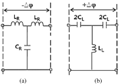
Figure 4: Showcasing the characteristics of (a) right-hand (RH) cell and (b) left-hand (LH) cell.
Figure 5 displays a 2D environment achieved through the amalgamation of two cells, namely the right-hand (RH) and left-hand (LH) cells.
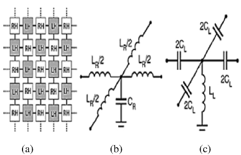
Figure 5: (a) Diagram of a 2-D ZIM medium produced by the combination of RH and LH cells, (b) two-dimensional RH cell, and (c) two-dimensional LH cell.
In Fig. 6, the absence of phase shift along a segment l in two merged cells (Right-Handed/Left-Handed) is shown. The voltage measurements are taken at the black nodes.
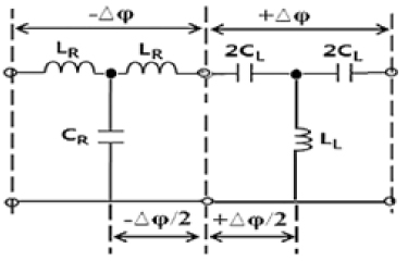
Figure 6: Zero-phase shift ensured by the combination of RH/LH cells.
To prevent reflection of electromagnetic energy, it is essential that the right-hand (RH) and left-hand (LH) cells possess identical characteristic impedances, as indicated by equation (33):
| (33) |
Equation (33) establishes the equality expressed in (34), thus:
| (34) |
Furthermore, for coherence, the right-hand (RH) and left-hand (LH) cells should exhibit identical absolute values in their electrical phase shifts. This requirement is encapsulated in the relationships outlined in equations (35a) and (35b):
| (35a) | ||
| (35b) |
The equality yields equation (36), expressed as:
| (36) |
Leveraging equations (35) and (36), we are able to express the ensuing relationship as equation (37):
| (37) |
We infer that LR and CL constitute a series resonator, whereas CR and LL form a parallel resonator. Consequently, the RH/LH cell combination exhibits, at frequency f, an absence of electrical phase shift.
Therefore, at the operational frequency , this amalgamation gives rise to a novel entity termed the CRLH cell, as depicted in Fig. 7.
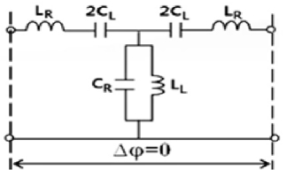
Figure 7: CRLH cell obtained by combining RH/LH cells.
The introduced phase shift by this novel cell is 0. When condition equation (34) is met, it signifies a balanced CRLH cell. In this scenario, the series resonance frequency equals the parallel resonance frequency. These frequencies are determined by equations (38a) and (38b) as:
| (38a) | |
| (38b) |
The resonance frequency 0=se=sh serves as the pivotal point marking the transition between the RH (Right-Handed) and LH (Left-Handed) regions on the scatter diagram, as illustrated in Fig. 8.
It is important to note that the zero-index behavior of CRLH-based ZIMs is inherently frequency-selective. The optimal ZIM effect occurs near the balanced resonance frequency (), where the refractive index approaches zero and the phase velocity becomes theoretically infinite. Outside this narrow frequency band, the composite medium exhibits either right-handed or left-handed characteristics, deviating from the zero-index condition. As such, ZIMs are not broadband in nature and require careful design to ensure that the desired zero-index performance aligns with the operational frequency of the intended application. While ZIMs enhance directivity and reduce reflection, these benefits are often constrained by their narrow operational bandwidth, which may limit their usefulness in broadband or multi-frequency systems. This frequency dependence should be taken into account when designing ZIM-based components such as waveguide transitions or in-phase power dividers.
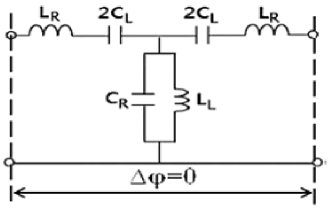
Figure 8: CRLH cell resulting from the combination of RH/LH unit cells in the balanced case defined by equations (38a) and (38b).
At the operating pulse frequency , we can infer that LR and CL constitute a series resonator, whereas CR and LL form a parallel resonator. Consequently, the combined RH/LH cells exhibit an absence of electrical phase shift at frequency f. Hence, we can deduce that this amalgamation at the operational frequency delivers a novel cell, termed the CRLH cell, as depicted in Fig. 9.
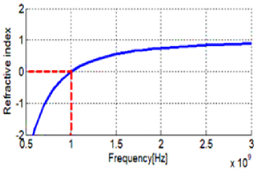
Figure 9: Variation of the refractive index for a CRLH cell as a function of frequency.
At 0, the propagation constant 2/ equals zero, indicating an infinite wavelength ( approaching infinity). Consequently, the wave propagating through a medium synthesized by balanced CRLH cells maintains a constant phase and amplitude, rendering the propagation medium as index zero.
Alternatively, considering RH and LH cells independently, we can calculate the propagation constant of the CRLH cell in the balanced case as the sum of the propagation constants of the RH and LH cells [34]:
| (39) |
The association between the propagation constant and the refractive index n is expressed by equation (40):
| (40) |
Therefore, the refractive index for a cell can be formulated as the summation of the refractive indices of RH and LH cells:
| (41) |
Here, and are provided by equations (42) and (43) [35]:
| (42) | ||
| (43) |
The formulations for inductances and capacitances are subsequently derived in equations (44) and (45) as:
| (44) | ||
| (45) |
When setting =1 and =-1, equation (44) yields 0. Consequently, ZIM is achieved in the CRLH medium. Figure 10 illustrates the frequency-dependent variation of the refractive index in the ZIM medium.
B. Routing electromagnetic energy through a narrow section of waveguide
In Fig. 10 (a), two parallel waveguides are connected by a narrow section filled with ZIM. The simulation results, shown in Fig. 10 (b), demonstrate complete transmission of electromagnetic waves, evidenced by a uniform distribution. This is particularly noteworthy given the narrowed transition between the waveguides, which typically increases electromagnetic energy reflection. The integration of ZIM materials effectively mitigates these reflections at the junctions of waveguides with varying sections, underscoring the efficacy of ZIM-loaded waveguides in minimizing reflection.
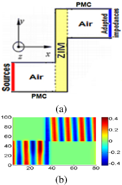
Figure 10: (a) Diagram of two waveguides interfaced by a sharp transition filled with ZIM materials and (b) voltage distribution.
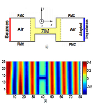
Figure 11: (a) Two waveguides connected via a third small section and (b) the voltage distribution.
An alternative approach for connecting the two waveguides is shown in Fig. 11 (a). The resulting total transmission of electromagnetic waves for this configuration is depicted in Fig. 11 (b).
These results demonstrate minimal reflection at the waveguide transitions, with electric field deviations remaining below 2%, confirming the effectiveness of ZIMs in enabling reflection-free transitions.
C. Reproducibility enhancements
To support reproducibility, all simulation parameters are listed in Table 1. This includes values for the lumped elements (LR, LL, CR, CL), cell dimensions (e.g., d/20), frequency of operation (0), and waveguide dimensions. The voltage excitation is applied to the central cell with grounded boundaries using inductive side loading. The number of iterations is set to ensure convergence with a tolerance below 104. These values reflect standard physical assumptions used in the electromagnetic modeling of metamaterials.
Table 1: Parameters used for WCIP-based ZIM modeling
| Parameter | Value |
| LR | 5 nH |
| LL | 5 nH |
| CR | 0.5 pF |
| CL | 0.5 pF |
| Cell Size (d) | /20 |
| Frequency (0) | 2.4 GHz |
| Excitation Source | Z Source (center cell) |
| Termination | Inductors (side walls) |
| Iterations (max) | 300 |
| Convergence Tolerance | 104 |
While ZIMs demonstrate promising capabilities in improving waveguide transitions and reducing signal loss, it is important to acknowledge the fabrication challenges inherent in realizing such structures. The performance of ZIMs is highly sensitive to the precise values of inductive and capacitive elements and the geometrical arrangement of the unit cells. Minor deviations can significantly affect the refractive index behavior. Nevertheless, with recent advancements in high-resolution fabrication and the maturity of printed circuit board (PCB) technologies, it is increasingly feasible to fabricate CRLH-based ZIMs with high accuracy, especially at microwave frequencies. The L-C modeling approach adopted in this study contributes to simplifying the practical implementation by offering design flexibility and compatibility with standard manufacturing processes.
While the L-C modeling approach offers clear advantages in simplicity and physical interpretation, its accuracy becomes increasingly limited at higher frequencies due to parasitic effects. Stray capacitance, inductive coupling between elements, and substrate-related losses can introduce deviations from ideal behavior, particularly beyond the gigahertz range. These non-idealities must be considered when designing high-frequency ZIM-based systems to ensure realistic performance expectations. Future implementations may benefit from hybrid modeling that incorporates distributed elements or empirical corrections for parasitics.
IV. CONCLUSION
In conclusion, the iterative method, grounded in the principles of wave dynamics, has proven to be highly efficient in both computational time and precision when applied to the analysis of almost periodic two-dimensional structures. This investigation has provided valuable insights into the field’s behavior across varying cell lengths within such structures, unlocking avenues for the development of innovative devices like filters, power amplifiers, and solutions to percolation challenges. Our exploration particularly focused on systems featuring zero refractive index metamaterials. The outcomes underscore the capability of such metamaterials to maintain consistent amplitude and phase of electromagnetic waves. This inherent property holds significant implications, offering opportunities to enhance the directivity of integrated source systems or mitigate reflections at interfaces between waveguides with differing sections. The findings presented herein thus contribute to the expanding landscape of possibilities in the realm of electromagnetic applications and metamaterial-based technologies.
REFERENCES
[1] A. K. Jha, A. Lamecki, M. Mrozowski, and M. Bozzi, “A highly sensitive planar microwave sensor for detecting direction and angle of rotation,” IEEE Transactions on Microwave Theory and Techniques, vol. 68, no. 4, pp. 1598-1609, 2020.
[2] M. Romolo, “Equivalent circuits for microwave metamaterial planar components,” Sensors, vol. 24, no. 7, p. 2212, 2024.
[3] H. Aymen, Z. Houaneb, and H. Zairi, “A terahertz tunable attenuator based on hybrid metal–graphene structure on spoof surface plasmon polaritons waveguide,” Physica B: Condensed Matter, vol. 644, p. 414208, 2022.
[4] B. Souad, A. Mehadji, and B. Hadjira, “Iterative approach investigation on the fractal Hilbert curve low-pass filters: Analysis and measurements,” Journal of Computational Electronics, vol. 19, pp. 1695-1704, 2020.
[5] E. Yang, U. Patel, M. A. Barry, A. McEwan, and P. C. Qian, “Microwave antenna design for cardiovascular applications: A comparison between a balanced and unbalanced microwave ablation antenna,” IEEE Journal of Electromagnetics, RF and Microwaves in Medicine and Biology, vol. 7, no. 4, 2023.
[6] A. Hlali, Z. Houaneb, and H. Zairi, “Modeling of magnetically biased graphene coupler at terahertz frequency through an improved anisotropic WCIP method,” IEEE Transactions on Magnetics, vol. 56, no. 8, pp. 1-8, 2020.
[7] A. M. Karim, T. Elbellili, A. Gharsallah, and H. Baudrand, “Wave propagation in RH/LH periodic lumped circuits using iterative method WCIP,” Progress in Electromagnetics Research M, vol. 82, pp. 29-38, 2019.
[8] M. Anouar, M. A. Ennasar, L. Setti, and F. Mustapha, “Design, analysis, of high-performance antennas for 5G communications analysis using WCIP,” Progress in Electromagnetics Research C, vol. 135, pp. 211-226, 2023.
[9] O. Afef, A. Hlali, and H. Zairi, “Numerical investigation of a new sensor for blood glucose detection using an improved wave concept iterative process method,” International Journal of Numerical Modelling: Electronic Networks, Devices and Fields, vol. 35, p. e3001, 2022.
[10] A. M. Karim, H. Baudrand, T. Elbellili, and A. Gharsallah, “Almost periodic lumped elements structure modeling using iterative method: Application to photonic jets and planar lenses,” Progress in Electromagnetics Research M, vol. 55, pp. 121-132, 2017.
[11] E. Taieb, M. K. Azizi, L. Latrach, H. Trabelsi, A. Gharsallah, and H. Baudrand, “Characterization of the composite right/left-handed transmission line metamaterial circuits using iterative method WCIP,” International Journal of Microwave and Wireless Technologies, vol. 9, no. 8, pp. 1645-1652, 2017.
[12] M. K. Azizi, T. Elbellili, H. Baudrand, and H. Trabelsi, “Transmission line approach of zero-index metamaterials and applications using a wave concept iterative method,” International Journal of Microwave and Wireless Technologies, vol. 11, no. 3, pp. 244-254, 2019.
[13] A. Gharsallah, A. Gharbi, L. Desclos, and H. Baudrand,” Analysis of interdigital capacitor and quasi-lumped miniaturized filters using iterative method,” International Journal of Numerical Modelling: Electronic Networks, Devices and Fields, vol. 15, no. 2, pp. 169-179, 2002.
[14] H. Trabelsi, A. Gharsallah, and H. Baudrand, “Analysis of microwave circuits including lumped elements based on the iterative method,” International Journal of RF and Microwave Computer-Aided Engineering, vol. 13, no. 4, pp. 269-275, 2003.
[15] A. Noemen and H. Baudrand, “WCIP method for multiple-loop antennas around a spherical media,” IET Microwaves, Antennas & Propagation, vol. 13, no. 5, pp. 666-674, 2019.
[16] A. Sassi, N. Sboui, A. Gharbi, and H. Baudrand, “Modeling of waveguide filter using wave concept iterative procedure,” Circuits and Systems, vol. 12, no. 2, pp. 13-22, 2021.
[17] A. Hlali and H. Zairi, “Performance analysis of dynamically controllable terahertz grounded coplanar waveguide attenuator based on graphene using wave concept iterative process method,” International Journal of RF and Microwave Computer-Aided Engineering, vol. 31, no. 2, p. e22517,2021.
[18] G. Vincensius, “The simulation of the propagation of electromagnetic waves through a material with various thicknesses using Finite Difference Time Domain (FDTD),” Valley International Journal Digital Library, vol. 57, no. 61, 2023.
[19] S. Gedney, “Introduction to the finite-difference time-domain (FDTD) method for electromagnetics,” Cham, Switzerland: Springer Nature, 2022.
[20] J. Wang and Q. Ren, “A 3-D hybrid Maxwell’s Equations Finite-Difference Time-Domain (ME-FDTD)/Wave Equation Finite Element Time-Domain (WE-FETD) method,” IEEE Transactions on Antennas and Propagation, vol. 71, no. 6, pp. 5212-5220, 2023.
[21] P. Liu, J. Li, and V. Dinavahi, “Matrix-free nonlinear finite-element solver using transmission-line modeling on GPU,” IEEE Transactions on Magnetics, vol. 55, no. 7, pp. 1-5, 2019.
[22] A. Ragusa, H. Sasse, and A. Duffy, “1.5 D Transmission Line Matrix Model to account for skin effects and impedance mismatches in transmission lines,” in 2022 IEEE MTT-S International Conference on Numerical Electromagnetic and Multiphysics Modeling and Optimization (NEMO), Limoges, France, pp. 1-4, 2022.
[23] E. Peter and C. Vanneste, “Huygens’ principle in the transmission line matrix method (TLM). Local theory,” International Journal of Numerical Modelling: Electronic Networks, Devices and Fields, vol. 16, no. 2, pp. 175-178, 2003.
[24] Z. Chen and M. M. Ney, “On the relationship between the time-domain and frequency-domain TLM methods,” IEEE Antennas and Wireless Propagation Letters, vol. 7, pp. 46-49, 2008.
[25] S. Iman and S. M. Riad, “TFDTLM-a new computationally efficient frequency-domain transmission-line-matrix method,” IEEE Transactions on Microwave Theory and Techniques, vol. 48, no. 7, pp. 1089-1097, 2000.
[26] Z. Houaneb, H. Zairi, A. Gharsallah, and H. Baudrand,” A new wave concept iterative method in cylindrical coordinates for modeling of circular planar circuits,” in Eighth International Multi-Conference on Systems, Signals & Devices, 2011.
[27] S. K. Podilchak, A. P. Freundorfer, and Y. M. M. Antar, “Planar surface-wave sources and metallic grating lenses for controlled guided-wave propagation,” IEEE Antennas and Wireless Propagation Letters, vol. 8, pp. 371-374, 2009.
[28] M. Anouar, L. Setti, and R. Haffar. “Design, analysis, and modeling using WCIP method of novel microstrip patch antenna for THz applications,” Progress in Electromagnetics Research C, vol. 125, pp. 67-82, 2022.
[29] S. Alayet, J. Y. Siddiqui, Y. Antar, and A. Gharsallah, “Characterization of UWB antipodal tapered slot antenna using wave concept iterative procedure,” in 2015 1st URSI Atlantic Radio Science Conference (URSI AT-RASC), 2015.
[30] L. Latrach, M. K. Azizi, A. Gharsallah, and H. Baudrand, “Study of one dimensional almost periodic structure using a novel WCIP method,” International Journal on Communications Antenna and Propagation, vol. 4, no. 6, 2014.
[31] D. Hadri, A. Zugari, and A. Zakriti, “Conception and characterisation of a novel 5_Shaped antenna for 5G application using WCIP method,” Australian Journal of Electrical and Electronics Engineering, vol. 18, no. 2, pp. 69-79, 2021.
[32] M. K. Azizi, L. Latrach, A. Gharsallah, and H. Baudrand, “Analytic model of a one-dimensional quasi-periodic structure by using a novel WCIP method,” International Journal of Electrical Electronics and Telecommunication Engineering, vol. 43, no. 12, 2012.
[33] N. Raveu, T. P. Vuong, I. Terrasse, G.-P. Piau, and H. Baudrand, “Near fields evaluated with the wave concept iterative procedure method for an E-polarisation plane wave scattered by cylindrical strips,” Microwave and Optical Technology Letters, vol. 38, no. 5, pp. 403- 406, 2003.
[34] T. Zhai, J. Shi, S. Chen, D. Liu, and X. Zhang, “Achieving laser ignition using zero index metamaterials,” Optics Letters, vol. 36, no. 14, pp. 2689-2691, 2011.
[35] H. F. Ma, J. H. Shi, B. G. Cai, and T. J. Cui, “Total transmission and super reflection realized by anisotropic zero-index materials,” New Journal of Physics, vol. 14, no. 12, p. 123010, 2012.
BIOGRAPHIES
Mohamed Karim Azizi was born in Tunis, Tunisia, on 26 December 1979. He received the M.Sc. degree in Telecommunications from SupCom in 2008. He received the Ph.D. degree in Electronics from Faculty of Sciences of Tunis, Tunisia, in 2013. He is currently an associated Professor in the department of computer Sciences in The Higher Institute of Multimedia Arts of Manouba, ISAMM, Tunisia. His research interests include metamaterials, metasurfaces, and graphene antennas.

Kawther Mekki is an Assistant Professor in Computer Engineering at the University of Hail, Saudi Arabia. She holds a Ph.D. in Electronics with a specialization in Radio Frequency (RF) systems. Her research interests include wireless communications, chipless RFID technologies, Internet of Things (IoT), and embedded systems. Mekki has published several peer-reviewed articles in leading international journals and conferences, and she actively participates in collaborative research projects in RF and IoT technologies.

Taieb Elbellili was born in Kasserine, Tunisia, on 29 April 1980. He received the M.Sc. degree in Electronic Systems from Faculty of Sciences of Tunis, Tunisia, in 2006. Since 2015, he is working toward his Ph.D. His research focuses on computational electromagnetic methods for metamaterials modelling.
ACES JOURNAL, Vol. 40, No. 7, 579–590
doi: 10.13052/2024.ACES.J.400702
© 2025 River Publishers