A Wideband, High Gain and Low Sidelobe Array Antenna for Modern ETC Systems
Lan T. Tran, Chinh D. Khuat, and Lam V. Phi
Department of Electrical and Electronic Engineering
University of Transport and Communications, Hanoi, 100000, Vietnam
ttlan@utc.edu.vn, linhchinh07@gmail.com, pvlam@utc.edu.vn
Submitted On: February 7, 2023; Accepted On: May 23, 2023
ABSTRACT
Modern electronic toll collection (ETC) systems are currently moving towards a system design that is capable of fast and optimal payment handling for a single lane. Thus, the antenna of a roadside reader unit (RSU) needs to provide sufficient coverage over the vehicle lane during a payment cycle. In this paper, a left-hand circularly polarized (LHCP) 24 array antenna is proposed for European standard RSU readers at 5.8 GHz. The proposed array antenna consists of patch element antennas with parasitic elements to enhance gain and bandwidth. Sequential phase rotation feeding networks are applied to make the antenna low-profile. By using the optimized nut-shaped metasurface, the antenna can achieve higher gain due to concentrated radiation power in the boresight direction. The antenna has a wide impedance bandwidth of 2.34 GHz (37.73%), axis ratio bandwidth of 2.07 GHz (32.9%), high gain of 17 dBi, and sidelobe level (SLL) lower than -15 dB at 5.8 GHz. Especially, half-power beamwidths are 34 and 17 in horizontal and vertical planes, respectively, which covers sufficient space for a single lane while avoiding interference with other lanes. The performance of the proposed antenna is verified by measured results. It showed that the proposed antenna is a promising candidate for ETC applications.
Index Terms: circularly polarized antenna, FFETC, high gain, metasurface, RSU antenna, wideband antenna.
I. INTRODUCTION
The free-flow electronic toll collection (FFETC) is an important part of the intelligent transportation system (ITS), which allows vehicles on the highway to not to have to stop when passing through a toll station. This helps to improve traffic efficiency and reduce congestion, accidents, and environmental pollution. The structure of the FFETC system consists of a roadside unit reader (RSU) at the gate and an onboard unit (OBU) on the vehicle’s window. They communicate with each other through the dedicated short-range communication (DSRC) standard. DSRC is a new technology that allows high-speed data transmission, while the accuracy and security are also superior to previous technologies like RFID [1]. Therefore, this technology has been deployed in many major countries around the world such as the United States, Japan, and European countries.
In Europe, two DSRC standards, EN12253 and EN302571, were established for CEN DSRC and ITS DSRC by the European Committee for Standardization (CEN) and the European Telecommunications Standards Institute (ETSI) [2, 3]. In particular, CEN DSRC is used for transportation applications with high reliability and performance in high-speed non-stop single-flow or multi-flow environments. For an RSU, EN12253 specifies the antenna operating at 5.8 GHz with a minimum bandwidth of 20 MHz. The beamwidth is limited to a vertical angle of 70, and a power of 33 dBm. Outside this coverage, the radiated power must be less than 18 dBm. In other words, the sidelobe level (SLL) of the antenna should be less than -15 dB. The polarization of the antenna is left-hand circularly polarized (LHCP) with a high polarization isolation of 15 dB in the main direction and 10 dB within thehalf-power beamwidth.
Studies have shown that an antenna with a main beam in H plane that is too wide should not be used because it can cause interference with neighboring lanes. The recommended half-power beamwidth is about 20 and the SLL is less than -15 dB [4]. On the other hand, for the payment to be guaranteed on the condition that the vehicle does not need to decelerate, the payment cycle between OBU and RSU must be very short, no more than 200 ms [5]. One solution is to reduce the central processing unit (CPU) cycles in the RSU (i.e. increase clock frequency). However, this solution is not feasible because the highest clock frequency currently does not exceed 100 MHz, and increases the cost of the RSU. Another possible solution is to design an antenna for the RSU with a transmission range to cover the vehicle’s mileage in a billing cycle. Through this solution, RSU costs can be significantly reduced.
An FFETC system is set up as shown in Fig. 1. The RSU is mounted on the gate at the height of h, and made with the vertical axis at an angle , is the half-power beamwidth (HPBW) of the antenna in the vertical plane. An OBU is installed on a vehicle whose distance to the road surface is h. To ensure a payment cycle takes place, the distance MN must be long enough (or must be wide enough) when the vehicle is traveling in one payment cycle at the allowed speed of v. There are two main loss factors influencing communication between RSU and OBU: the first one is free space loss L and the second is loss from car windows L. L depends on the instantaneous distance between OBU and RSU r, while L depends on the material of car windows. For accurate communications, the received OBU power P must be greater than -43 dBm [5]. Based on the Friis transmission equation, P is represented by equation (1). Parameters P, L, L and G are factors outside RSU. So the only solution to make sure the received signal is large enough is to increase G. Thus, our design criteria that need to be achieved for the RSU antenna are high gain, vertical HPBW wide enough, horizontal HPBW 20 and SLL -15 dB. According to European standards, h 5.5 m [5] and assuming h = 1.5 m. Therefore, the relationship between vehicle speed v and is given in Table 1.
| (1) |
The paper [5] also proposed an antenna with a radiation pattern with a vertical beam of 30 and a horizontal beam of 15. However, the antenna SLL is high, about -12.5 dB. Recently, there has been some research on antenna design for RSU. In [6], a 1010 antenna array is proposed with a high gain of up to 14.3 dBi. The antenna used a Woodward and Lawson feeding structure to achieve a low SLL of -28.2 dB. But, it has a symmetrical radiation pattern of about 37 in both vertical and horizontal planes, a fairly wide beam, and can cause interference to adjacent lanes. In addition, in the operating frequency range, the axis ratio value of 2.7 dB represents a low circular polarization purity. The 12-element antenna array in [4] is more optimally designed for the EN12253 standard. It has a wide bandwidth of 1.13 GHz with 15 dB high polarization isolation, HPBW of 23, gain of 14.7 dBi at 5.8 GHz, and peak gain of 17 dBi at 5.9 GHz. In particular, its SLL is low, about -17 dB, thanks to the use of a Chebyshev feeding network. But, its beamwidths have not been optimized based on the vehicle’s speed to cover a distance for a payment circle. Similarly, this is a weak point of the antennasin [7–11].
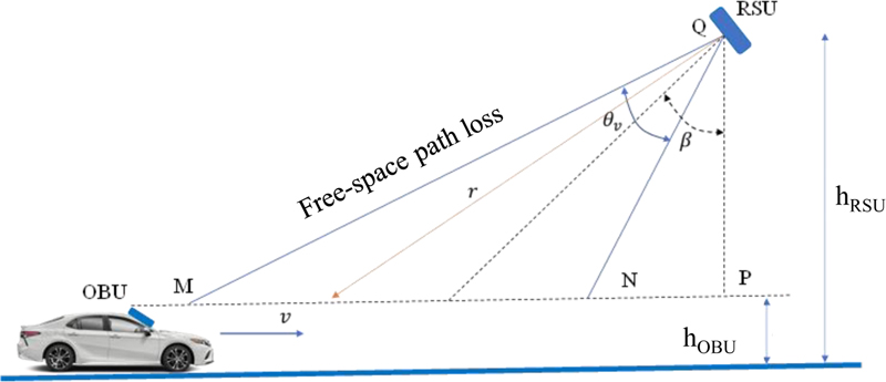
Figure 1: The communication between OBU and RSU.
In [12], a 24 antenna array was introduced with high gain, vertical (V), and horizontal (H) beamwidths of 33.2 and 17.1, respectively. However, the SLL is quite high, around -13 dB, and its performance has not been verified by measurement. Therefore, this study will continue to improve it to meet the requirements for an RSU antenna as mentioned above. The double circle unit cell is analyzed and optimized to get characteristics of the metasurface with both negative permittivity (0) and negative permeability (0) to enhance the performance of the proposed antenna by reducing SLL and improving AR bandwidth. Compact size is another advantage of the proposed antenna by utilizing a sequential phase rotation feeding network. FR-4 is used for fabrication to obtain a low-cost antenna. Finally, the performance of the proposed antenna is verified by measured results.
Table 1: The relationship between the beamwidth and the velocity of vehicle v
| v (km/h) | 60 | 100 | 130 |
| (degree) | 22 | 34.6 | 39 |
The paper is organized into three parts. Part II presents the antenna design process, which will analyze the antenna components including the unit cell, element antenna, 22 array antenna, and 24 array antenna with the reflector. Some conclusions and discussions are given in Part III.
II. ANTENNA DESIGN
A. Unit cell
LHCP patch antennas are widely used for ETC applications. However, they are generally low gain, so improving gains for these antennas is a challenge for researchers. Several solutions have been proposed, for example, using parasitic sheets [13, 14], deploying stacked patches [15, 16] and implementing metamaterials [17, 18, 27–31]. The use of the parasitic patch in [13] can improve gain very well, and it can also extend the circular polarization bandwidth for antennas deployed on the same plane. However, the disadvantage of this structure is that the antenna size may be larger. In [15], deploying two patch layers was proposed. Simulation and measured results show that the gain of the antenna is significantly improved from 5 dBi to 10.5 dBi. This method does not increase the size of the antenna, but it does make the antenna thicker and more difficult to fabricate due to misalignment between layers. The gain of the antenna in [17] was enhanced by 2 dBi thanks to applying a metasurface placed on the main radiation patch. The antennas in [17–22] also implemented a metasurface, but the special feature of these designs is that the metasurface is capable of re-polarization from LP (linear polarization) to CP. Thereby, we can see that using a metasurface is not only to reconfigure the polarization but also to increase gain.
In this study a new unit cell and a metasurface are proposed to improve gain, and AR bandwidth, and to create a low-profile antenna. The structure of the proposed unit cell is shown in Fig. 2 (a). It is nut-shaped, made up of two circles of radius r = 2.1 mm with a total length of k = 6 mm. Each unit cell is printed on an FR-4 substrate with the permittivity = 4.3 and thickness of 1.6 mm. Compared to the unit cell in [12, 25], four corners of the unit cell are cut apart as shown in dashed boxes. The unit cell is rotated 45 compared with the Y-axis direction. The proposed unit cell is simulated by CST Studio Software [26] with the boundary condition as shown in Fig. 2 (b), where Port 1 is located 4 mm far from the surface of the unit cell, and Port 2 is located at a long distance away because this side of the metasurface is open so it is chosen as one wavelength.
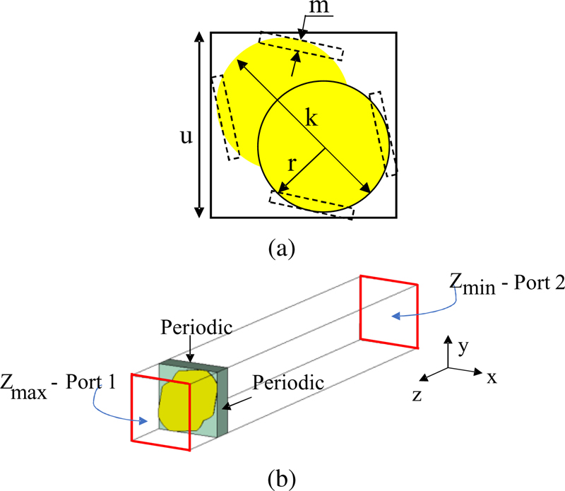
Figure 2: (a) Geometry of unit cell and (b) numerical unit cell model for simulation.
The proposed unit cell is truncated and has a smaller size compared to the non-truncated unit cell (N-T unit cell) in [25], as a result, the mutual coupling between element antennas in the proposed array is reduced. Then, the SLL of the proposed array antenna is enhanced. The performance of the proposed unit cell and metasurface when they are integrated into the element antenna will be presented in the next subsections.
B. Element antenna
The element antenna is designed with the metasurface structure proposed in subsection A. The structure of the element antenna is shown in Fig. 3. It has two layers: the lower layer is a reference antenna that was introduced in [12, 25], and the upper layer is the proposed metasurface, which is a 44 unit cell array. The distance between unit cells is d. The distance between the two layers is h. The size of the ground plane is WW.
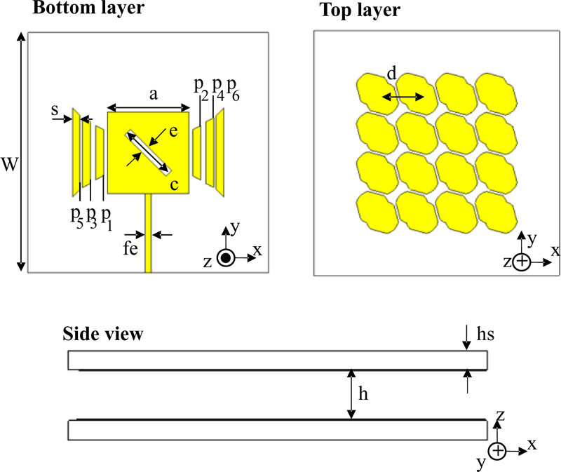
Figure 3: Structure of element antenna using the proposed metasurface (a = 10.5, c = 7.5, d = 5, e = 1, fe = 0.7, g = 0.5, g = 0.7, g = 0.3, h = 4, hs = 1.6, p = 5, p = 7, p = 8, p = 9, p = 9.5, p = 11.5, s = 1, W = 33) Unit: mm.
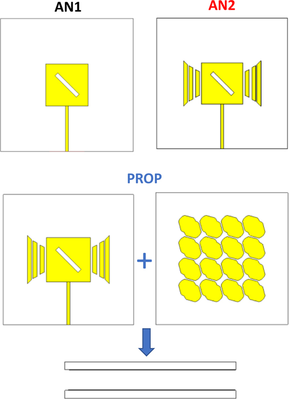
Figure 4: Three different versions of the element antenna.
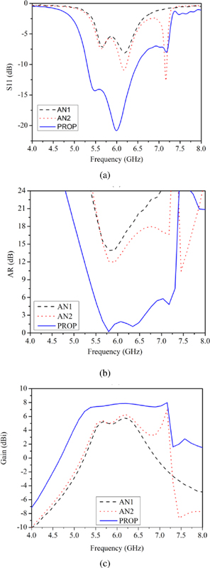
Figure 5: Simulated results of three antenna versions in (a) S, (b) AR, and (c) gain.
To analyze the role of antenna components, three antenna versions (AN1, AN2, and PROP) in Fig. 4 are simulated and compared with each other. AN1 is a square patch antenna with a diagonal slot in the middle. AN2 consists of AN1 and six parasitic patches, and the final model PROP contains AN2 and the proposed metasurface. PROP is the proposed element antenna. The simulation results of these three antennas are shownin Fig. 5.
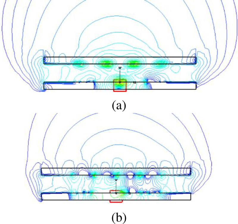
Figure 6: E-field of the element antenna (a) with the N-T unit cell and (b) with the T unit cell.
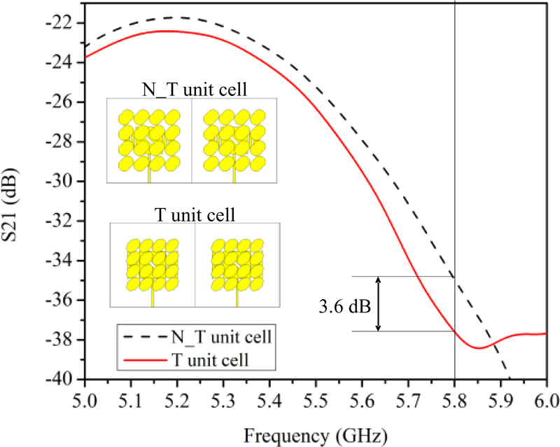
Figure 7: Simulated S between two element antennas with the N-T unit cell and the T unit cell.
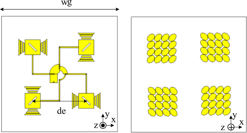
Figure 8: The proposed 22 antenna array.
Figure 5 reveals that AN1 resonates at 5.7 GHz and 6.2 GHz with S values of -7 dB and -8 dB. The lowest axis ratio value is 15 dB at 5.8 GHz while the peak gain is 5.7 dBi at 6.2 GHz. After adding the six isosceles trapezoidal parasitic patches, the AN2 resonates better at 6.2 GHz, while an additional resonance appears at the higher frequency of 7.25 GHz. The AR curve appears with three sharp peaks where there are small AR values of 12 dB, 16.5 dB, and 10.5 dB at 5.8 GHz, 7.2 GHz, and 7.4 GHz. The gain value at the low-frequency band seems to be constant, however, due to the resonance at 7.2 GHz, the gain at this frequency reaches 6 dBi. It can be seen that AN1 and AN2 have weak resonance, low gain, and no circularly polarized radiation. After adding the proposed metasurface, the impedance matching is greatly improved, and PROP achieves an impedance bandwidth (Imp. BW) of 1.2 GHz (20.34%). At the same time, the elliptical polarization of AN2 is also converted to circular polarization when using the proposed metasurface with an axial ratio bandwidth (AR BW) of 1 GHz (16.39%). In particular, the gain of PROP is significantly improved in the entire working frequency range with a very stable high value in the range of 78 dBi (the gain curve is flat as shown in Fig. 5 (c)). Thus, using the proposed metasurface significantly improves the performance of circularlypolarized antennas.
As mentioned in subsection A, the T unit cell reduces mutual coupling between element antennas. This is proved in Fig. 6, which shows the electric field (E-field) of the element antenna in two cases with the T unit cell and the N-T unit cell. It can be seen that the E-field in the case of the T unit cell is more concentrated in the boresight direction than that in the case of the N-T unit cell. Similarly, S of two-element antennas is also simulated in these two cases as shown in Fig. 7. At 5.8 GHz, S is reduced to 3.6 dB. Thus, the SLL of the proposed array is improved by using this T unit cell.
C. The proposed 22 array antenna
The 22 antenna array is designed as shown in Fig. 8. The four-element antennas are fed by the sequential phase rotation feeding network which was introduced in [25]. This feeding network contributes to enhancing the AR bandwidth and making the proposed antenna compact. The distance between the element antennas is de = 37 mm and the total length is wg = 80 mm. Some fabrication photos of this antenna are shown in Fig. 9. Simulation and measured results in S, gain, and AR are given in Fig. 10. The measured result in S has a good agreement with the simulation ones. Figure 10 (b) provides information about the gain, where the maximum gain is 14.3 dBi at 5.8 GHz. The simulated AR bandwidth is 2 GHz (32.5%). The SLL of the 22 array antenna in the case of the T unit cell is lower than that in the case of the N-T unit cell as shown in Fig. 11. The measured radiation patterns agree well with the simulation ones. The HPBW are approximately 34 and the maximum SLL is -15.3 dB. Thus, the performance of the 22 array antenna is verified by the measured results with a high gain and wide bandwidth. But, its HPBWs are symmetrical, which has not satisfied for requirements of ETC antennas in terms of beamwidths as mentioned above. As a result, the 22 array antenna continues to be developed into a 24 array antenna presented in subsection D.
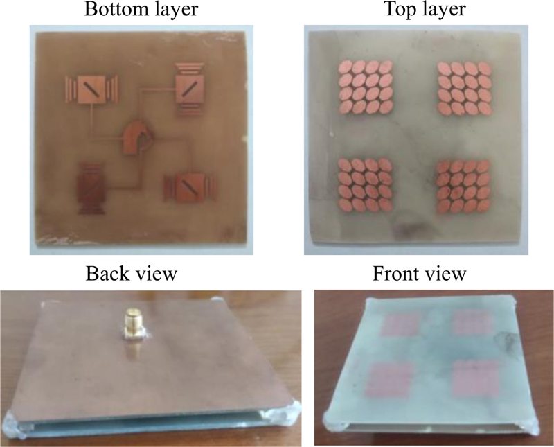
Figure 9: Photos of the fabricated 22 antenna arrays.
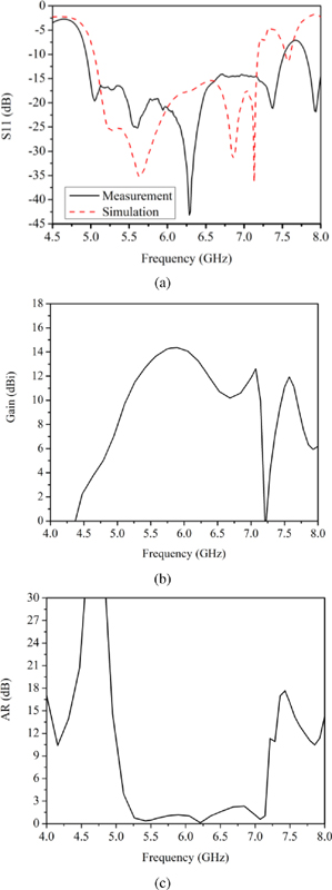
Figure 10: Simulation and measured results of the 22 antenna arrays: (a) S, (b) gain, and (c) AR.
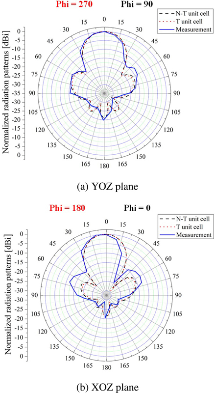
Figure 11: Simulation and measured radiation patterns of the array antenna in two cases: N-T unit cell and T unit cell in two planes (a) YOZ plane, (b) XOZ plane.
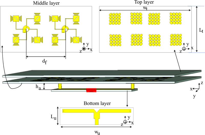
Figure 12: The proposed 24 antenna array (W = 160, L = 80, h = 7, L = 17.5, W = 75, d = 53. Unit: mm).
D. The proposed 24 array antenna
The 24 antenna array is proposed in Fig. 12. It consists of three layers: the top layer is metasurface, the middle layer is the 24 patch antenna array, and the bottom layer is a T-shaped feeding network. The overall size of the proposed antenna is WL. The distance between two 22 arrays is d and the distance between the bottom layer and the middle layer is ha. The T-shaped feeding network has an input of the 50 line. A /4 segment with a characteristic impedance of 35 is used to match impedances for two 50 outputs, which are connected to two 22 array antennas by coaxial cables. The size of the feeding network is WL. Fabrication photos of the 24 array antenna are shown in Fig. 13.
The simulation and measured results of the 24 array are shown in Figs. 14 and 15, which show the impedance bandwidth of 2.34 GHz (37.56%), and the 3-dB AR bandwidth of 1.865 GHz. (30.6%), and the peak gain of 16.6 dBi at 5.8 GHz. The vertical beamwidth ( = 0) and the horizontal beamwidth ( = 90) are 35 and 18.6, respectively. The proposed 24 array antenna meets almost all requirements for an ETC antenna, but the SLL of this antenna is -13.3 dB, so is quite high. Therefore, a reflector is added to compressthe SLL.
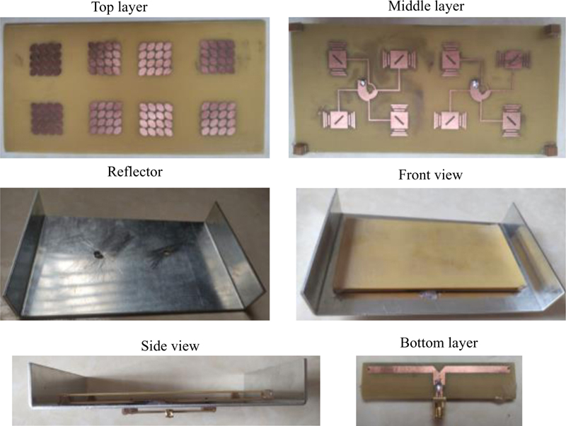
Figure 13: Fabrication photos of the proposed 24 array antenna.
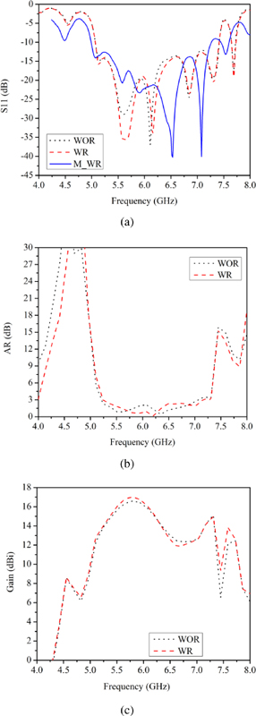
Figure 14: Simulation and measured results of three cases without reflector (WOR), with reflector (WR), and measurement with reflector (M_WR) in (a) S11, (b) AR, and (c) gain.
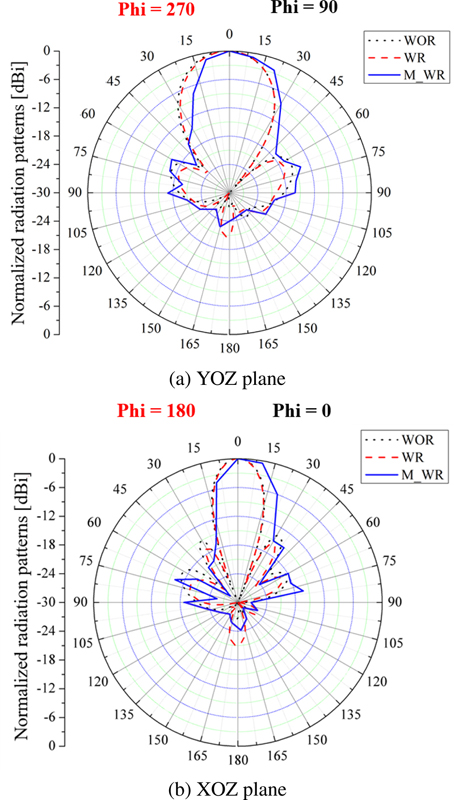
Figure 15: Simulation and measured radiation patterns of the array antenna in three cases: without reflector (WOR), with reflector (WR), and measurement with reflector (M_WR), in two planes (a) YOZ plane, (b) XOZ plane.
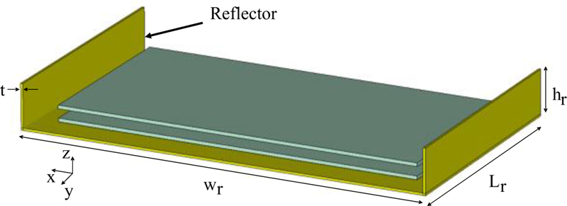
Figure 16: The 24 array antenna with the reflector.
Figure 16 shows the 24 array antenna with the reflector. The size of the reflector is wLh. Two metal plates are placed on either side of the antenna, where the SLLs need to be reduced. The height of these two plates h is the main parameter affecting the SLL reduction. The larger h is, the smaller the sidelobe is. In addition, the wider reflector also helps to reduce the sidelobe.
In the plane = 0, the SLL is significantly reduced from -13.3 dB to -15.7 dB while the SLL is -17.2 dB in the plane = 90 as given in Fig. 15. The vertical beamwidth ( = 0) and the horizontal beamwidth ( = 90) are 34 and 17, respectively. The measured radiation patterns are also shown in Fig. 15. There is little difference between the simulation and measured results, which is caused by measurement and fabrication errors.
The effect of this reflector is more clearly shown by simulation results in Fig. 14. Figure 14 (a) shows that the impedance bandwidth is almost unchanged while 3-dB AR bandwidth is extended to 2 GHz (32.9%) in Fig. 14 (b), and the gain is improved to 17 dBi at 5.8 GHz. In summary, the additional reflector can reduce the SLL, and increase both the AR bandwidth and the gain of the proposed 24 array antenna.
III. DISCUSSION AND CONCLUSION
Table 2 provides a comparison of the proposed 24 array antenna with some recently reported ETC antennas. It can be seen that the proposed antenna has wider impedance bandwidth and AR bandwidth than almost all the other antennas 4–10], except for the antenna [25]. The high gain of 17 dBi is another merit of the proposed antenna compared to the other antennas. Also, unlike the proposed antenna, most of the other antennas do not have optimized beamwidths in order to cover the vehicle’s mileage in a payment cycle. Moreover, the size of the proposed antenna is more compact than the antennas in [5, 6]. In summary, a novel nut-shaped unit cell was proposed to improve the proposed array antenna in terms of impedance and AR bandwidths, SLL, and gain in this study. The problem of interference and vehicle speed was considered in designing the proposed array antennas. The vehicle can pass the ETC with a speed of more than 100 Km/h. The SLL of the proposed antenna was optimized to be smaller than -15 dB by adding a reflector. By applying the sequential phase rotation feeding network, the proposed array antenna is low-profile with enhanced AR bandwidth. Moreover, the proposed array antenna was verified by measured results. It is found that the proposed 24 array antenna has met most of the requirements for ETC antennas, and therefore, it is a suitable candidate for RSUs in modern ETCsystems.
Table 2: A performance comparison between the proposed 24 antenna with other studies
| Ref. | Imp. BW (%) |
AR BW (%) | Gain (dBi) | V-H HPBW (degree) | SLL (dB) | Size (mm) |
| [4] | 34.48 | 19.4 | 14.7 | 23-23 | 17 | 1721720.8 |
| [5] | 7.86 | Nm | 16.6 | 35.4-15.7 | 12.5 | 2001800.8 |
| [6] | 1 | Nm | 14.9 | 33-33 | 26 | 3903400.8 |
| [7] | 2.58 | Not CP | 12 | 40-40 | 10 | 10310313 |
| [8] | Nm | 19.4 | 18 | 20-20 | 16 | Nm |
| [9] | 3.73 | LP | 9.9 | Nm | Nm | 55301.6 |
| [10] | 1.37 | Nm | 13 | Nm | 12 | Nm |
| [12] | 37.75 | 35.52 | 17 | 33-17 | 13 | 152766.4 |
| This work | 37.73 | 32.9 | 17 | 34-17 | 15.7 | 18010630 |
| Not mentioned: Nm. | ||||||
ACKNOWLEDGMENT
This research is funded by University of Transport and Communications (UTC) under grant number T2021-DT-005TD.
REFERENCES
[1] J. Czako, Where is Tolling Tech Taking Us? ITS International, https://www.itsinternational.com/its1/feature/where-tolling-tech-taking-us, 2019.
[2] CEN (European Committee for Standardization), “Road transport and traffic telematics – dedicated short-range communication – physical layer using microwave at 5.8GHz,” Oct. 2004.
[3] ESTI (European Telecommunications Standards Institute), “Intelligent Transport Systems (ITS); Radiocommunications equipment operating in the 5 855 MHz to 5 925 MHz frequency band; Harmonized EN covering the essential requirements of article 3.2 of the R&TTE Directive,” May 2013.
[4] T. Varum, J. N. Matos, P. Pinho, and R. Abreu, “Non-uniform broadband circularly polarized antenna array for vehicular communications,” IEEE Transactions on Vehicular Technology, vol. 65, no. 9, pp. 7219-7227, Sep. 2016.
[5] B. Franciscatto, “Design and implementation of a new low-power consumption DSRC transponder,” Department of Electronics, University of Grennoble, Grenoble, France, July 2014.
[6] J. S. Jang, N. H. Kang, Y. W. Koo, and J. K. Ha, “Planar array antenna design with beam shaping for ETCS-RSE,” Asia-Pacific Microwave Conference Proceedings (APMC), Seoul, Korea, Nov. 2013.
[7] N. Rimbault, A. Sharaiha, and S. Collardey, “Very low profile helix antenna feeding resonant cavity for ETC system,” 16th International Symposium on Antenna Technology and Applied Electromagnetics (ANTEM), Victoria, BC, Canada, July 2014.
[8] Y. Zhao and L. Li, “Circular polarized Fabry-Perot resonator antenna for dedicated short range communication,” 2014 IEEE International Wireless Symposium (IWS 2014), Xi’an, China, Mar. 2014.
[9] R. M. Kingsta and K. Seyatha, “Design and performance comparison of metamaterial superstrate antenna for DSRC applications,” 3rd International Conference on Trends in Electronics and Informatics (ICOEI), Tirunelveli, India, Apr. 2019.
[10] T. Varum, J. N. Matos, R. Abreu, and P. Pinho, “Non-uniform microstrip antenna array for Rx DSRC communications,” IEEE Antennas and Propagation Society International Symposium (APSURSI), Memphis, TN, USA, 2014.
[11] Y. Zhao, “Circular polarized Fabry-Perot resonator antenna for dedicated short range communication,” IEEE International Wireless Symposium, Xi’an, China, Dec. 2014.
[12] D. C. Khuat and T. L. Tran, “A high gain wideband array antenna based on metasurface for ETC application,” Transport and Communications Science Journal, vol. 73, no. 7, pp. 723-733, Sep. 2022.
[13] N. Hussain, H. H. Tran, and T. T. Le, “Single-layer wideband high-gain circularly polarized patch antenna with parasitic elements,” AEU - International Journal of Electronics and Communications, vol. 113, no. 1, Jan. 2020.
[14] M. S. Ibrahim, “Design of low-cost, circularly polarized, and wideband U-slot microstrip patch antenna with parasitic elements for WiGig and WPAN applications,” Applied Computational Electromagnetics Society (ACES) Journal, vol. 34, no. 9, pp. 1453-1456, Sep. 2019.
[15] V. S. Kraanthi, R. B. Sandhya, P. V. Sitaraman, S. Aora, C. Sriharsha, K. V. Senthil, and D. Venkataramana, “High gain circularly polarized stacked patch antenna at C-band for GEO satellite telemetry application,” IEEE Indian Conference on Antennas and Propagation (InCAP), Ahmedabad, India, Dec. 2019.
[16] A. Michel, P. Nepa, and J. Qiu, “Compact dual-band circularly polarized stacked patch antenna for microwave-radio-frequency identification multiple-input-multiple-output application,” International Journal of Antennas and Propagation, vol. 2021, pp. 1-13, May 2021.
[17] S. X. Ta and I. Park, “Low-profile broadband circularly polarized patch antenna using metasurface,” IEEE Transactions on Antennas And Propagation, vol. 63, no. 12, pp. 5929-5934, Dec. 2015.
[18] J. Dong, C. Ding, and J. Mo, “A low-profile wideband linear-to-circular polarization conversion slot antenna using metasurface,” Materials Journal, vol. 13, no. 5, pp. 1-13, Mar. 2020.
[19] L. Yuan, H. Y. Xuan, L. Z. Wei, C. S. Ting, X. X. Ming, and G. Jing, “Design of a compact wideband CP metasurface antenna,” International Journal of RF and Microwave Computer-Aided Engineering, vol. 30, no. 10, pp. 1-8, Oct. 2020.
[20] Z. Tao, H. Zhang, H. Xu, and Q. Chen, “Novel polarization conversion metasurface based circular polarized slot antenna with low profile,” 2019 Cross-Strait Quad-Regional Radio Science and Wireless Technology Conference, Taiyuan, China, Aug. 2019.
[21] Q. Zheng, C. Guo, and J. Ding, “Wideband and low RCS circularly polarized slot antenna based on polarization conversion of metasurface for satellite communication application,” Microwave and Optical Technology Letters, vol. 60, no. 3, pp. 679-685, Feb. 2018.
[22] C. Qiang and Z. Hou, “Dual-patch polarization conversion metasurface-based wideband circular polarization slot antenna,” IEEE Access, vol. 29, no 5, pp. 74772-74777, Nov. 2018.
[23] M. T. Le, Q. C. Nguyen, and T. P. Vuong, “Design of high-gain and beam steering antennas using a new planar folded-line metamaterial structure,” International Journal of Antennas and Propagation, vol. 2014, pp. 1-16, Sep. 2014.
[24] N. H. Nguyen, T. D. Bui, A. D. Le, A. D. Pham, T. T. Nguyen, Q. C. Nguyen, and M. T. Le, “A novel wideband circularly polarized antenna for RF energy harvesting in wireless sensor nodes,” International Journal of Antennas and Propagation, vol. 2018, pp. 1-9, Mar. 2018.
[25] D. C. Khuat, V. L. Phi, and T. L. Tran, “A wideband high gain circularly polarized antenna based on nut-shape metasurface,” International Conference on Advanced Technologies for Communications (ATC), Hanoi, Vietnam, Oct. 2022.
[26] CST Microwave Studio, ver. 2018, Computer Simulation Technology, Framingham, MA, 2008.
[27] A. A. Abbas, B. S. Samet, and H. A. Abbas, “A compact high gain wideband metamaterial, antenna for sub-6 GHz applications,” Applied Computational Electromagnetics Society (ACES) Journal, vol. 37, no. 8, pp. 886-892, Aug. 2022.
[28] B. Qiu1, Y. Xia, and Y. Li, “Gain-enhanced wideband circularly polarized antenna with a non-uniformmetamaterial reflector,” Applied Computational Electromagnetics Society (ACES) Journal, vol. 37, no. 3, pp. 281-286, Mar. 2022.
[29] H. Q. Tian, J. L. Wang, D. Han, and X. Wang, “A gain-enhanced dual-band microstrip antenna using metasurface as superstrate configuration,” Applied Computational Electromagnetics Society (ACES) Journal, vol. 36, no. 12, pp. 1586-1593, Dec. 2021.
[30] L. N. Nguyen, “A MIMO antenna with enhanced gain using metasurface,” Applied Computational Electromagnetics Society (ACES) Journal, vol. 36, no. 4, pp. 458-464, Apr. 2021.
[31] A. Sethi and R. Rajni, “Determination of electromagnetic parameters of a new metasurface comprising of square loop,” Journal of Engineering Science and Technology, vol. 13, no. 1, pp. 48-57, Jan. 2018.
BIOGRAPHIES

Lan T. Tran was born in Haiphong, Vietnam, in 1988. She received her B.S. and M.S. degrees in telecommunication engineering from the University of Transport and Communications, Hanoi, Vietnam, in 2011 and 2013, respectively. She received her Ph.D. degree in computer, physics, and electrical engineering from Yokohama National University, Yokohama, Japan. She is now a lecturer at the University of Transport and Communications. Her current research interest is the design of antennas for wireless communication systems.

Chinh D. Khuat was born in Hanoi, Vietnam, in 2000. He is studying Electronic and Telecommunication Engineering at the University of Transport and Communications, Hanoi, Vietnam. His current research interest is the design of antennas for ETC systems and rectennas for RF energy harvesting.

Lam V. Phi received his B.E. and M.E. degrees in electrical and electronic engineering from the University of Transport and Communications, Hanoi, Vietnam, in 2011 and 2014, respectively. He received his Ph.D. degree in physics, electrical, and computer engineering from Yokohama National University, Yokohama, Japan, in 2019. His current research interests include robotics, AI, control theory, motion control, internet of thing (IoT) and intelligent transport system (ITS).
ACES JOURNAL, Vol. 38, No. 5, 333–342
doi: 10.13052/2023.ACES.J.380506
© 2023 River Publishers