Modeling and Analysis of a Proposed AC-DC C-Core Heteropolar Radial Hybrid Magnetic Bearing
N. Boutra, R. Mehasni, and M. Feliachi
1Laboratoire d’électrotechnique de Constantine (LEC)
Université des frères Mentouri Constantine 1, Route Ain Elbey, 25000 Constantine, Algérie
boutra.nacir@gmail.com, Algérieboutra.nacir@gmail.com, mehasni@yahoo.fr
2Laboratoire IREENA (UR 4642)
Nantes Université, CRTT, 37 boulevard de l’Université, CS 90406, 44600 Saint-Nazaire, France
mouloud.feliachi@univ-nantes.fr, Francemouloud.feliachi@univ-nantes.fr
Submitted On: March 20, 2023; Accepted On: November 18, 2024
ABSTRACT
In this study, a new C-Core heteropolar radial hybrid magnetic bearing (HRHMB) driven by a three-phase power inverter is proposed. The use of a three-phase inverter driving technology improves the performance of magnetic bearings in terms of cost and power consumption. The force-current and the force-displacement characteristics of the proposed HRHMB are linear and the magnetic field coupling between the X and Y directions is significantly reduced. To analyze the proposed HRHMB, the configuration, working principle and required mathematical model based on the equivalent magnetic circuit (EMC) method are firstly presented. Then the load capacity and important parameters design are deduced. A comparison between the results obtained by the used analytical approach and those given by the finite element method (FEM) allowed verification of the developed mathematical model’s accuracy. Compared with the twelve-pole HRHMB, the proposed HRHMB improves bearing capacity, reduces mass, and enhances cost efficiency and performance, making it highly suitable for large journal diameter applications.
Index Terms: Heteropolar, hybrid magnetic bearing, magnetic circuit decoupling, second air gap, three-phase inverter driving.
I. INTRODUCTION
Many application areas make use of magnetic bearings (MBs). By using applied electromagnetic forces, they can keep rotors in levitation. Compared to mechanical bearings, they allow for the removal of frictional losses, extending the system’s lifespan [1, 2]. In addition to their capacity to avoid environment pollution, they can also reduce vibrations and limit maintenance. The cited advantages have allowed MB technology to be increasingly exploited in high-speed rotating equipment [3–6]. The hybrid magnetic bearing (HMB) combines the advantages of low loss of passive MB and the control ability of active MB [7–9]. HMBs are characterized by the presence of copper coils and permanent magnets (PMs). PMs create the biased field which is modulated by the electromagnetic field generated by coils to produce a controllable magnetic force between the rotor and each ferromagnetic pole. Homopolar and heteropolar are the two kinds of radial hybrid magnetic bearing (RHMB) that are largely used and studied [10–12]. The homopolar type has the advantage of low power consumption. In this one, the PM is inserted between two stators to create the bias flux in the axial direction. The double stator design is inherently more complex than the single stator design. In contrast, the heteropolar radial hybrid magnetic bearing (HRHMB) with a single stator has a lower axial length, compact structure, and simple mechanical construction. In [13–15], three novel decoupling HRHMB structures with second air gap are presented. The control flux generated by the coils is separated from the PM, which considerably reduces the power loss. A novel structure of HRHMB has been proposed with small volume compared to the classical structure where an analytical model is developed to investigate its performance [16]. In [17], a comparison of main performance indexes such as rotor core loss, displacement stiffness and current stiffness between a novel proposed HRHMB and conventional one under the same constraints is made.
Compared with RHMBs driven by four or two power amplifiers, the three-pole and six-pole RHMBs are designed to improve space utilization and reduce volume. Researchers agree that it is very attractive to design a MB driven by a three-phase inverter because of the low cost and low power consumption [18, 19]. Three-phase inverter drive technology is used in three-pole [20, 21], six-pole [18, 22] and twelve-pole MBs [23] if the sum of the current equals zero. The disadvantages of three-pole and six-pole RHMBs are the strong nonlinearity between the magnetic force and the control current and the magnetic coupling between the two directions X and Y that makes control of the rotor position more complex.
To meet practical engineering demands, efficient MBs are crucial for the reliable and secure functioning of rotor systems. In this paper, a new HRHMB, specifically suitable for large journal diameter applications, is introduced. By optimizing the structure, we aim to significantly reduce the mass of the MB, resulting in decreased material usage and reduced production costs.
This paper proposes a new HRHMB structure driven by a three-phase inverter with a second air gap. This structure combines the benefits of decoupling HRHMBs with those of RHMBs driven by a three-phase inverter, and overcomes the shortcomings caused by the non-symmetrical traditional three-pole and six-pole structures. The new structure offers the dual advantages of a lower power amplifier requirement and weak magnetic field coupling between the X and Y directions. The linearity of the force-current and force-displacement characteristic facilitates the implementation of a simple control mechanism.
Construction and operation of the proposed HRHMB are thoroughly examined. The configuration is modeled using the equivalent magnetic circuit (EMC) approach to determine force-current and force-displacement properties. Various design parameters are then determined based on the EMC. The analytical model’s results are contrasted with those obtained via the finite element method (FEM). Compared to twelve-pole HRHMB, the suggested construction demonstrates a higher bearing capacity. Consequently, the proposed HRHMB not only meets the prerequisite of sufficient bearing capacity but also offers a cost-effective and technically sound solution for large journal diameter applications.
II. STRUCTURE AND MATHEMATICAL MODEL
A. Structure
In this work a new structure of a HRHMB is proposed. The structure shown in Fig. 1 contains a laminated stator and rotor to reduce its eddy current loss. Six C-Core magnetic poles are windings and are arranged symmetrically. The yokes between adjacent two C-Core poles are made of non-magnetic material. Six identical PMs radially magnetized in NSSNNSSNNSSN configuration are inserted in the six C-Core poles to produce bias fluxes. Three phase coils, where each one is composed of four windings, are connected in series and wrapped around four poles (, , , and belong to P-phase, P A, B, C). The coils are driven by a three-phase inverter to produce control fluxes. This driving mode reduces the cost construction and switching loss compared with power amplifiers driving mode. With the introduction of the second air gap, the control flux is directed away from the PM. If the three coils are not energized and the rotor is perfectly in the equilibrium position, the resultant magnetic force generated by PMs and acting on the rotor is zero, due to the symmetrical structure. When energizing the coils, the produced magnetic field will be superposed with bias flux. These two fields are additive in the two ferromagnetic poles and subtractive in the two opposite poles which creates a magnetic force acting on the rotor in the direction between the two opposite ferromagnetic poles. If the magnetic fluxes generated by A-phase are taken as an example, the two fields are additive in and and are subtractive in and . Thus, the magnetic force is the result of the force in () direction and the force in () direction.
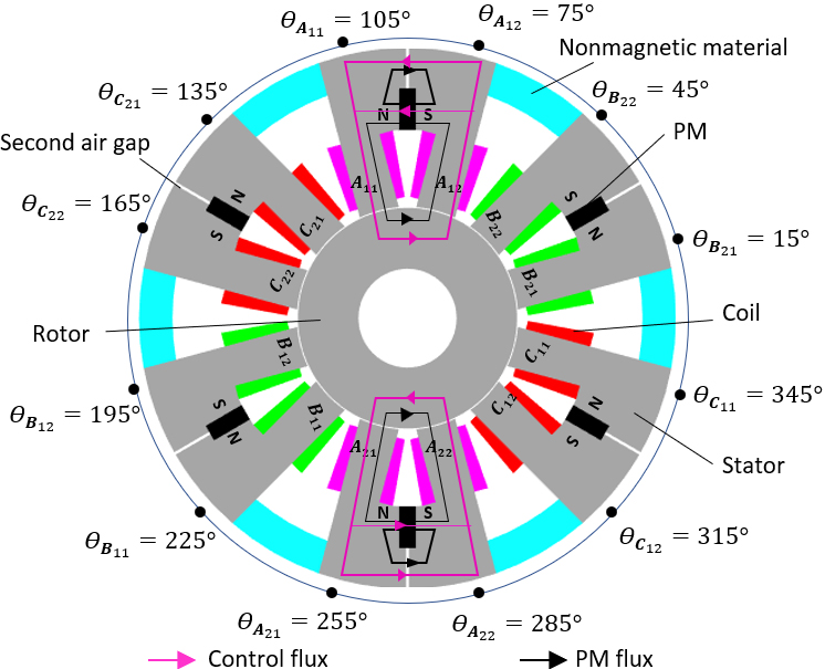
Figure 1: Structure of proposed heteropolar radial hybrid magnetic bearing.
B. Mathematical model
The path of the PM magnetic circuit and the electric magnetic circuit of the C-Core formed by two poles ( ) is shown in Fig. 2. Here we neglect factors such as reluctance of the iron core, the eddy current loss and magnetic flux leakage.
For the six C-Core poles, , , and are the magnetic fluxes in air gaps generated by the PM, , , and are the magnetic fluxes in air gaps generated by control currents, N is the number of turns in single coil, , and are the currents in the three-phase coils, is the magnetomotive force of the PM, is the reluctance of the PM and is the reluctance of the second air gap. The air gap reluctances (l [, , , , , , , , , , , ] ) can be expressed as:
| (1) |
where is the air gap length, is the permeability of a vacuum,is the section area of the pole, and x and y are the eventual rotor displacements in X and Y directions, respectively. is the polar angle of the l-pole axis.
Based on the EMC method, the PM fluxes can be calculated as:
| (2) |
where is the correction factor of the PM magnetic circuit, l and k .
The electromagnetic fluxes can be expressed as:
| (3) |
where is the correction factor of electromagnetic magnetic circuit, l and k .
Taking , equation (3) can be rewritten as:
| (4) |
The virtual work method is applied to acquire the magnetic forces for the twelve poles. The forces generated in the air gap poles can be calculated as:
| (5) |
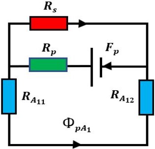
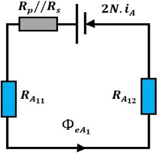
Figure 2: Equivalent magnetic circuits of the C-Core pole (a) PM bias flux circuit and (b) control flux circuit.
Projecting the forces in equation (5) into the x-axis and y-axis, respectively, each phase generates two directional forces. The six magnetic suspension forces can be expressed as:
| (6) |
The magnetic forces in the X and Y directions are expressed as:
| (7) |
The three-phase current, and can be transformed to two-phase control currents and by the Clark transformation:
| (8) |
To estimate the force-displacement stiffness and and force-current stiffness and in the X and Y directions, respectively, radial suspension forces near the equilibrium position are linearized using the first-order Taylor expansion as:
| (9) |
The stiffness coefficients , , , and are given by:
| (10) |
and are given by:
| (11) |
III. RADIAL LOAD CAPACITY ANALYSIS
When the rotor is in the central position, the flux densities in the air gap poles are equal to the bias flux density, which is equal to half of the saturation flux density.
The suspension force is maximum when the current . According to (8) and as the sum of the three-phase current is zero, it can be taken that . In this condition, we have , which gives:
| (12) |
The suspension force is only determined by the flux densities in the air gaps , , , , , , , and is maximum when the current , flux density and flux density. If we make , it can be taken that , according to equation (8). In this condition, we have , whichgives:
| (13) |
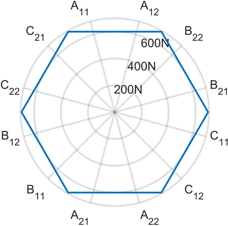
Figure 3: Load capacity of the proposed hybrid magnetic bearing as a function of orientation angle.
The maximum suspension forces in each direction of the proposed structure are compared to those given by six-pole and twelve-pole structures (see Table 1).
Table 1: Maximum suspension force in each direction
| LoadCapacity | Twelve-Pole Structure | Proposed Structure |
| X direction | ||
| Y positive direction | ||
| Y negative direction |
Compared to the twelve-pole HRHMBs [23], the maximum load capacity of the proposed C-Core HRHMB is increased by 1.93 times. Taking, the dependence of the load capacity on the orientation angle is shown in Fig. 3. The radius of the polar plot indicates load capacity at an orientation angle. It can be seen from Fig. 3 that the minimum value of the maximums of the suspension forces is obtained at the orientation angles located in the six centers of the six C-Core poles. The maximum load capacity of the proposed bearing is the maximum force in the Y direction .
The load capacity of the HRHMB is primarily determined by the required pole section area. Using FEM, we compared the two types of magnetic bearings with the same pole section area (rotor diameter and pole width) and bias flux. In this comparison, the pole width varies between 10 mm and 40 mm, the pole section covers 50% of the journal, and the aspect ratio (axial length/outer diameter of the rotor) is 0.5. Figure 4 shows total mass versus load capacity. We can conclude from this figure that the new HRHMB has a lower mass compared to the twelve-pole. When the load capacity of the twelve-pole structure reaches its maximum value of 3661 N with a pole width of 40 mm, the total mass of the novel HRHMB decreases by 38% for the same load capacity. Therefore, as the journal diameter increases linearly with the increase in pole width, the proposed HRHMB is suitable for applications involving large journal diameters.
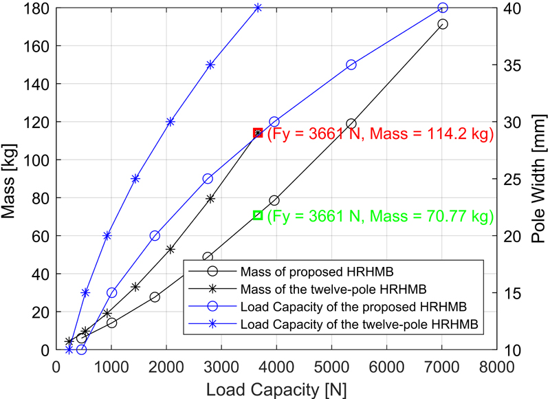
Figure 4: Total mass versus load capacity.
IV. PARAMETER DESIGN
A. Magnetic pole area
According to equation (12), the area of the magnetic pole can be expressed as:
| (14) |
where is the width of the pole and l is the axial length. is taken to be equal to half of one-twelfth of the inner stator perimeter length and defined as:
| (15) |
where is the inner diameter of the stator.
B. Second air gap
To obtain the optimal value of that maximises the Y direction force , the force-current stiffness in equation (9) can be treated as the objective function with variable . We solved the equation thus:
| (16) |
The optimal value of the reluctance of the second air gap can be given by:
| (17) |
C. PM dimensions
The bias flux density is chosen to be equal to half of the saturation flux density to maximize the load capacity. For the rotor equilibrium position, the flux densities in the air gaps are equal to the bias flux density. According to equations (2) and (17), the width of the PM can be calculated as:
| (18) |
where is the relative permeability of the PM and is the coercivity of the PM. The design parameters of the proposed HRHMB are shown in Table 2.
Table 2: Parameters of the proposed HRHMB
| Parameter | Symbol | Value |
| Radial air gap length | 0.4 mm | |
| Second air gap length | 1 mm | |
| Saturation induction density | 1 T | |
| Magnetic pole width | 10.4 mm | |
| Outer diameter of stator | 183 mm | |
| Inter diameter of stator | 80 mm | |
| Axial length | 50 mm | |
| PM height | 10.7 mm | |
| PM width | 6 mm | |
| Number of turns | N | 232 |
| Load capacity | 600 N |
V. VERIFICATION OF THE PERFORMANCE OF THE PROPOSED HRHMB
To verify the performance of the proposed RHMB in comparison to the existing structures, a numerical simulation based on application of the 2D FEM has been achieved. The distribution of the magnetic field that permits the computation of different characteristics on which our analysis is based is presented in Fig. 5.
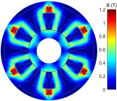
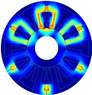
Figure 5: Distribution of flux densities (a) PM bias flux density and (b) superposition of PM bias flux and control flux ().
Figure 5 (a) shows the distribution of magnetic field provided only by PM without rotor eccentricity. We can see that the flux density is symmetrically distributed. When energizing the coils in the Y direction (, ), the symmetry of the distribution of the magnetic field will be lost (see Fig. 5 (b)). The magnetic field in the Y positive direction is enhanced whereas the magnetic field in the Y negative direction is reduced.
Figure 6 (a) shows the effect of displacement of the rotor on air gap flux density when the coils are not energized. Without rotor displacement (no eccentricity), we have obtained identical air gap flux density at the poles and symmetrical distribution in view of the two axes. The bias flux in each air gap is 0.5 T, which verifies the design requirements. However, when the rotor displaces in the Y positive direction, it can be seen that the air gap flux densities under poles , , , , and increases while the air gap flux densities under poles , , , , and decreases. However, the flux density waveform is not uniformly distributed because of the non-uniformity of the air gap.
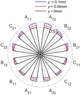
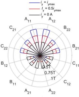
Figure 6: Polar flux density waveform in the air gap (a) y-displacement of rotor without coils energizing and (b) variation of without rotor eccentricity.
Figure 6 (b) shows the effect of coil current on the air gap density when the rotor is at the equilibrium position. It can be shown that with increasing coil current , the flux density of each part in Y positive direction is increased while the flux density of each part in Y negative direction is decreased. It can be seen for example that the bias and control fluxes are additive in poles ,, ,, and and subtractive in the opposite poles ,, ,, and .
To verify the accuracy of the achieved modeling of the proposed HRHMB, the analytically and numerically obtained results concerning the force-current and force-displacement characteristics are compared and presented in Fig. 6. Figure 7 shows that magnetic force is almost linearly proportional to control current and displacement. Comparison of analytical and numerical values of current and displacement stiffness is listed in Table 3.
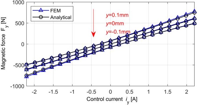
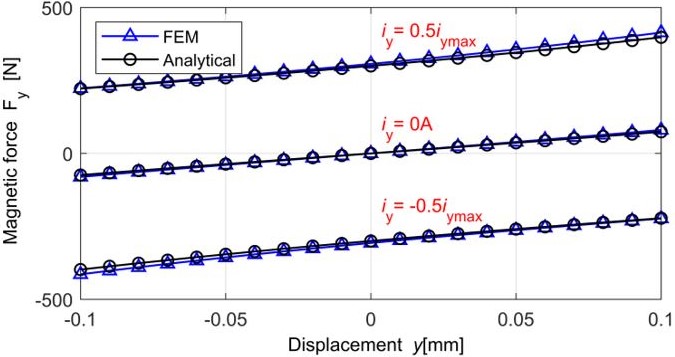
Figure 7: components as a function of control current and rotor displacement (a) force-current relationship and (b) force-displacement relationship.
Table 3: Comparison of analytical and numerical stiffness of the proposed HRHMB
| Stiffness | Analytical | Numerical | Error |
| (N/A) | 272.17 | 278.38 | 2.23% |
| (N/mm) | 735.03 | 796.10 | 7.67% |
The maximum error between the analytical and numerical results is 7.67% for the displacement stiffness. This error is mainly related to the local saturation of the iron core that is not considered in the analytical computation. Based on all of the aforementioned findings, it can be concluded that the developed analytical model can be properly used for the design of the proposed HRHMB.
Variations of the magnetic force components as a function of the two control currents and are presented in Fig. 8. These results have been obtained for a current changing from 2.54 A to 2.54 A and a current changing from A to 2.2 A. It can be observed that the magnetic force is almost proportional to the coil current and independent of Also, the magnetic force is almost proportional to the coil current and independent of
To identify the nature of dependency between force and rotor eccentricity, we have estimated the effect of rotor displacement on the force components and . The obtained results are presented in Fig. 9.
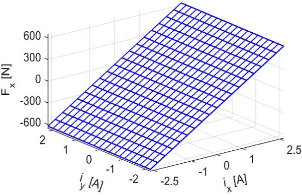
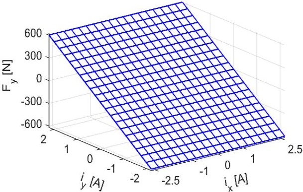
Figure 8: Force-current dependence (a) variation of the component and (b) variation of the components.
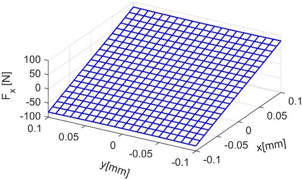
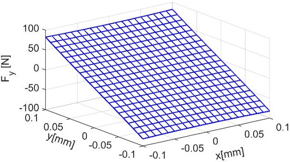
Figure 9: Force-displacement relationship (a) variations and (b) variations.
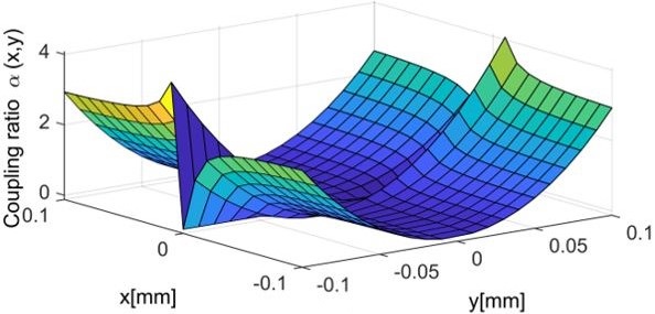
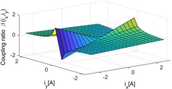
Figure 10: Magnetic force coupling (a) caused by rotor displacement and (b) caused by control current.
The results shown in Fig. 9 have been obtained by considering eccentricities in X and Y directions varying from mm to 0.1 mm. It can be seen that a linear dependency exists between the force components and the displacement. Moreover, the magnetic force does not depend on y displacement and the magnetic force does not depend on x displacement.
To examine variations of the magnetic force due to X direction displacements and X direction control currents, we compute the coupling ratios defined as:
| (19) |
Figure 10 (a) illustrates variation of the coupling ratios with the different rotor displacements in the X and Y directions when all coils are not energized. As shown, rotor displacements in the X direction have minimal impact on the magnetic force in the Y direction, with the maximum coupling effect less than 4.08%.
Figure 10 (b) shows the variation of the coupling ratios when the rotor is at the equilibrium position. Results indicate that the maximum coupling effect occurs when the control current is substantial while the control current is zero, with the maximum coupling effect less than 1.47%. These two coupling ratios indicate that the magnetic forces in the X and Y directions of the designed magnetic bearing are nearly independent of each other.
VI. CONCLUSION
In this paper, a new structure for HRHMB driven by a three-phase inverter is presented. The EMC method is used to analyze the linearity and the coupling characteristics of the proposed magnetic bearing. FEM analysis has permitted verification of the performance of the HRHMB validation of such an analysis. Compared to the existing HRHMB, the proposed HRHMB retains the advantages of the existing bearing and overcomes their drawbacks. The proposed HRHMB offers the advantage that there is very weak magnetic coupling between the X and Y directions. Moreover, the linear proportionality between the magnetic force and the control current facilitates the control. The proposed HRHMB demonstrates a higher load capacity compared to the twelve-pole given the same biased flux and journal diameter. Additionally, it offers an effective and reliable solution for applications with larger journal diameters.
REFERENCES
[1] G. Schweitzer and E. Maslen, Magnetic Bearings: Theory, Design, and Application to Rotating Machinery. Berlin, Germany: Springer-Verlag, 2009.
[2] T. Fan, J. Yu, Z. Sun, X. Liu, X. Zhang, J. Zhao, X. Yan, H. Zuo, and Z. Shi, “Theory and simulation of linearized force coefficients for active magnetic bearings with multiple magnetic poles,” Applied Computational Electromagnetics Society Journal (ACES), vol. 34, no. 04, pp. 598-604, 2019.
[3] K. Asami, A. Chiba, M. A. Rahman, T. Hoshino, and A. Nakajima, “Stiffness analysis of a magnetically suspended bearingless motor with permanent magnet passive positioning,” IEEE Transactions on Magnetics, vol. 41, no. 10, pp. 3820-3822, Oct. 2005.
[4] G. G. Sotelo, R. de Andrade, and A. C. Ferreira, “Magnetic bearing sets for a flywheel system,” IEEE Transactions on Applied Superconductivity, vol. 17, no. 2, pp. 2150-2153, 2007.
[5] J. Denk, D. Stoiber, H. Köpken, and H. Walter, “Industrialization of AMB system with standard drive technology,” IEEE Transactions on Magnetics, vol. 45, no. 12, pp. 5319-5325, Dec. 2009.
[6] F. Jiancheng, S. Jinji, X. Yanliang, and W. Xi, “A new structure for permanent-magnet-biased axial hybrid magnetic bearings,” IEEE Transactions on Magnetics, vol. 45, no. 12, pp. 5319-5325, Dec. 2009.
[7] A. V. Filatov and E. H. Maslen, “Passive magnetic bearing for flywheel energy storage systems,” IEEE Transactions on Magnetics, vol. 37, no. 6, pp. 3913-3924, Nov. 2001.
[8] M. A. Pichot, J. P. Kajs, B. R. Murphy, A. Ouroua, B. M. Rech, and R. J. Hayes, “Active magnetic bearings for energy storage systems for combat vehicles,” IEEE Transactions on Magnetics, vol. 37, no. 1, pp. 318-323, Nov. 2001.
[9] E. Y. Hou and K. Liu, “A novel structure for low-loss radial hybrid magnetic bearing,” IEEE Transactions on Magnetics, vol. 47, no. 1, pp. 4725-4733, Jan. 2011.
[10] F. Jiancheng, W. Xi, W. Tong, T. Enqiong, and F. Yahong, “Homopolar 2-pole radial permanent-magnet biased magnetic bearing with low rotating loss,” IEEE Transactions on Magnetics, vol. 48, no. 8, pp. 2293-2303, Aug. 2012.
[11] K. Kang and A. Palazzolo, “Homopolar magnetic bearing saturation effects on rotating machinery vibration,” IEEE Transactions on Magnetics, vol. 48, no. 6, pp. 1984-1994, June 2012.
[12] S. Jinji and F. Jiancheng, “A novel structure of permanent-magnet-biased radial hybrid magnetic bearing,” Journal of Magnetism and Magnetic Materials, vol. 323, no. 2, pp. 202-208, Jan. 2011.
[13] S. Xu and J. Sun, “Decoupling structure for heteropolar permanent magnet biased radial magnetic bearing with subsidiary air-gap,” IEEE Transactions on Magnetics, vol. 50, no. 8, pp. 1-8, Aug. 2014.
[14] J. Fang and C. Wang, “Design and optimization of a radial hybrid magnetic bearing with separate poles for magnetically suspended inertially stabilized platform,” IEEE Transactions on Magnetics, vol. 50, no. 5, pp. 1-11, May 2014.
[15] H. Wang, B. Xue, and S. Tang, “Modeling and analysis of E-Core permanent magnet biased radial magnetic bearing,” International Journal of Applied Electromagnetics and Mechanics, vol. 49, no. 2, pp. 179-193, 2015.
[16] L. Wu, D. Wang, Z. Su, K. Wang, and X. Zhang, “Analytical model of radial permanent magnet biased magnetic bearing with assist poles,” IEEE Transactions on Applied Superconductivity, vol. 26, no. 7, pp. 1-5, Oct. 2016.
[17] R. Zhu, W. Xu, C. Ye, and J. Zhu, “Novel heteropolar radial hybrid magnetic bearing with low rotor core loss,” IEEE Transactions on Magnetics, vol. 53, no. 11, pp. 1-5, Nov. 2017.
[18] L. Ji, L. Xu, and C. Jin, “Research on a low power consumption six-pole heteropolar hybrid magnetic bearing,” IEEE Transactions on Magnetics, vol. 49, no. 8, pp. 4918-4926, Aug. 2013.
[19] W. Zhang and H. Zhu, “Radial magnetic bearings: An overview,” Results in Physics, vol. 7, pp. 3756-3766, 2017.
[20] H. Zhu, S. Ding, and J. Jv, “Modeling for three-pole radial hybrid magnetic bearing considering edge effect,” Energies, vol. 9, no. 5, pp. 1-15, May2016.
[21] J. Ju and H. Zhu, “Radial force-current characteristics analysis of three-pole radial-axial hybrid magnetic bearings and their structure improvement,” Energies, vol. 9, no. 9, pp. 1-17, Sep.2016.
[22] M. Wu, H. Zhu, H. Zhang, and W. Zhang, “Modeling and multilevel design optimization of an AC-DC three-degree-of-freedom hybrid magnetic bearing,” IEEE Transactions on Industrial Electronics, vol. 70, no. 1, pp. 233-242, Jan. 2023.
[23] G. Liu, H. Zhu, M. Wu, and W. Zhang, “Principle and performance analysis for heterpolar permanent magnet biased radial hybrid magnetic bearing,” IEEE Transactions on Applied Superconductivity, vol. 30, no. 4, pp. 1-4, June 2020.
BIOGRAPHIES

Nacir Boutra was born in Ain M’lila, Algeria. He received the B.S. and M.S. degrees in Electrical Engineering from the University of Constantine, Algeria, in 2007 and 2010, respectively. He is currently working toward the Ph.D. degree at the Department of Electrical Engineering, in the same University, member of the LEC laboratory. His current research interests include magnetic bearing, numerical and analytical methods.

Rabia Mehasni was born in Grarem, Algeria, in 1970. He received the Ph.D. in Electrical Engineering from the University of Constantine, Algeria, in 2007. He has been with the Department of Electrical Engineering, University of Constantine, since 2000. He is currently Research Director at the LEC Laboratory. He has published in the field of magnetic separation. His research interests are in the field of numerical methods and modeling techniques to approach multidisciplinary problems.

Mouloud Feliachi is native of Biskra (Algeria). He is an Engineer of the “Ecole Nationale Polytechnique”, Algiers (1976), a Ph.D. of the “Conservatoire National des Arts et Métiers”, Paris (1981), and “Docteur d’Etat Es-Sciences Physiques” of “Institut National Polytechnique”, Grenoble (1986), all in Electrical Engineering. In 1987, he worked as an Engineer for the Leroy Somer company in Orléans. In 1988, he joined the University of Nantes (Institut Universitaire de Technologie - Saint-Nazaire) where he is Professor. He was Scientific Director of LRTI-Lab and Head of the Modeling and Simulation team in GE44-Lab. He is currently leading a Franch Algerian thematic network of research in Inductics, within IREENA Lab. His research interests are in hybrid analytical and numerical modeling of low frequency electromagnetic phenomena with emphasis on multiphysics and eddy current non-destructive testing and evaluation.
ACES JOURNAL, Vol. 39, No. 9, 814–822
doi: 10.13052/2024.ACES.J.390907
© 2024 River Publishers