A Dual-Polarization Broadband Coupling Feed Dipole Antenna Based on Artificial Magnetic Conductor
Z. N. Jiang1,2, Z. W. Li1, and Z. X. Wang1
1School of Electronic Science and Applied Physics
Hefei University of Technology, Hefei, China
jiangzhaoneng@hfut.edu.cn, 1335677546@qq.com, 1364665074@qq.com
2National Mobile Communications Research Laboratory
Southeast University, Jiangsu, China
Submitted On: April 18, 2023; Accepted On: February 8, 2024
ABSTRACT
A dual-polarized broadband coupled feed dipole antenna loaded with artificial magnetic conductor (AMC) structure is proposed. The proposed AMC structure with 44 elements shown in this paper consists of four perfect electrical conductor (PEC) rectangular strips and a ring to reduce the profile height of the dual-polarized dipole antenna. In addition, the dual-polarization antenna adopts coupling feed microstrip to excite two pairs of bow-tie patch. The overall size of the coupling feed dipole antenna is 1.11.10.09 at 5.5 GHz. Measured results shows that the proposed dual-polarization antenna loaded AMC exhibit a 25.2% common working bandwidth (4.75-6.12 GHz). The isolation is less than -14 dB, and the peak gain is 10.6 dBi. This dipole antenna with AMC structure has the virtues of low profile, wide band, and good radiation performance and it has the potential to be used in C-band communication.
Index Terms: artificial magnetic conductor, coupled feed, dual-polarization, low profile.
I. INTRODUCTION
With the evolution of wireless technology in the field of personal communications and military applications, under the limited spectrum resources, there are increasingly more requirements for the design of antennas in communication systems. In order to reduce the influence of multipath effect on wireless communication system, dual-polarized antennas are designed and have been widely used [1–3]. So as to achieve directional radiation and maximum gain, the patch of a traditional dipole is kept away from the metal floor about /4 [4]. This results in a higher profile of the antenna, but the AMC structure solves this problem well.
Two independent ports are often used to feed across dipole antenna to obtain vertical and horizontal polarization [5–7]. Reference [8] designed a dual-polarized cross slot antenna using two orthogonal slot radiators. The common impedance bandwidth of the antenna at Ports 1 and 2 is 1.56-2.73 GHz (54.5%), the isolation is greater than -26 dB, and the profile height is about 0.27. In [9], there is a pair of printed dipoles with a reflective ground to obtain two linear polarizations. The cross polarization of the dual-polarized dipole antenna is less than -30 dB within 575-722 MHz (22.7%), the port isolation is more than -35 dB, and the profile height is about 0.27 at 575 MHz. Although the antenna in [8] and [9] has good performance, it is difficult to integrate with microwave circuit due to its complex structure and high profile.
In this paper, a broadband dual-polarized coupled feed dipole antenna loaded with AMC is presented. The antenna adopts coupling feed to excite two pairs of bow-tie patch, which realizes horizontal polarization and vertical polarization, respectively. The measured results show that the common impedance bandwidth of this antenna is 4.75-6.12 GHz (25.2%). The coupling feed structure adopted in this paper provides a new design idea for the double polarized dipole antenna loaded with the AMC structure.
II. DUAL-POLARIZATION DIPOLE DESIGN
The geometry of the bow-tie dual-polarized cross dipole antenna is shown in Fig. 1. The antenna is composed of a pair of bow-tie radiation structures, strip coupling microstrip line, coaxial feed structure, dielectric cylinder and PEC reflector plate. The patch is printed on a square Rogers 5880 substrate with a thickness of 1.016 mm. The bow-tie shaped radiation structure is printed on the lower surface of the dielectric substrate as a dual-polarized radiator. Port 1 is connected to a 0 dipole to induce 0 polarization, and Port 2 is connected to a 90 dipole to induce 90 polarization. At the center frequency of 5.5 GHz, the theoretical value should be a quarter wavelength, that is, 13.6 mm. After simulation and optimization, the overall design of the dipole is W1+W2+W3=10.1 mm, which is slightly different from the theoretical value. The width of the microstrip line is calculated according to 50 ohms, and the calculated result is 3.1 mm, and the actual value is 3 mm. Commercial simulation software High Frequency Structural Simulator (HFSS) was used for simulation calculation. The optimization algorithm is a quasi-Newton method, whose basic idea is to find the estimated value of the minimum point by quadratic expansion of the objective function near the minimum point. Figure 2 shows the simulation results of the reflection coefficients for the dual-polarized antenna. Due to the difference between the two strip coupled microstrip lines, the reflection coefficients of Port 1 and Port 2 are slightly different. The working bandwidths of Port 1 and Port 2 are 5.36-5.67 GHz and 5.25-5.52 GHz, respectively. The common bandwidth is 5.36-5.52 GHz. The port isolation within the working bandwidth is less than -11 dB.
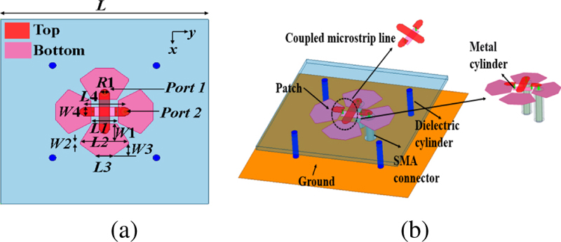
Figure 1: Geometry of the proposed dipole antenna: (a) top view and (b) side view.
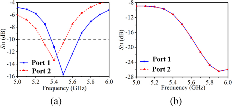
Figure 2: Simulation results of reflection coefficient (a) S and (b) S.
By introducing an AMC structure instead of a PEC reflector, we can improve the performance of crossed dipole dual-polarization antennas, such as reducing the profile, increasing the operating bandwidth, increasing the isolation, and improving the radiation characteristics. Figure 3 shows the designed AMC structure and the corresponding simulation of reflection coefficient curve. The patch unit is printed on the Arlon 880 dielectric substrate, with a thickness of 2 mm. The bottom of the dielectric substrate is a PEC layer. The optimized dimensions of AMC are as follows: S=15 mm, Ra=5.5 mm, Rb=7.4 mm, a=1.7 mm, and hamc=2 mm.
III. AMC UNIT DESIGN
It can be seen from Fig. 3 that the in-phase reflection bandwidth of AMC proposed in this section is 5-6.08 GHz, and the relative bandwidth is 19.5%. The frequency corresponding to the 0 reflection phase is close to the central frequency of 5.5 GHz, and the reflection coefficient modulus curve is above -0.06 dB, which basically shows the characteristics of total reflection.
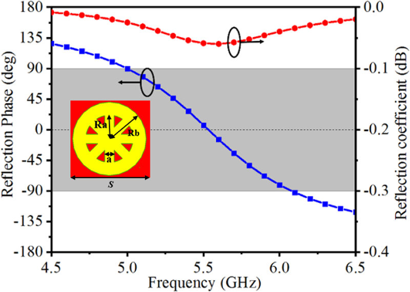
Figure 3: Geometry of the proposed AMC and simulation results of reflection coefficient.
In order to more intuitively explain the design idea of the AMC structure, Fig. 4 shows the two different AMC structures and the corresponding reflection characteristic curves. The initial AMC is a ring structure, and the in-phase reflection bandwidth is 4.16-4.6 GHz (10%). The reflection coefficient modulus is greater than -0.12 dB. In order to adjust the offset 0 reflection phase to the designed center frequency point of 5.5 GHz, it is necessary to move the reflection phase curve to the high frequency. Therefore, four rectangular structures are loaded on the initial AMC. It can be seen that the ring AMC loaded with rectangular branches not only has larger in-phase reflection bandwidth, but also has lower reflection loss, which proves the effectiveness of the design structure.
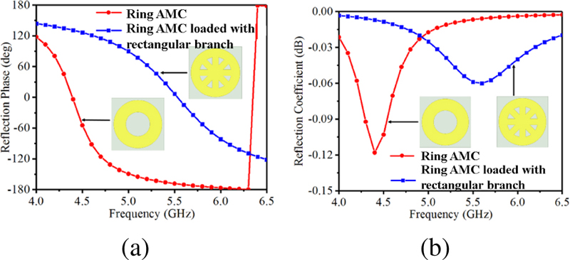
Figure 4: Reflection phase results of the proposed two AMC structures: (a) reflection phase and (b) reflection coefficient.
Figure 5 establishes the simple circuit model of the proposed AMC [10]. The gap between adjacent periodic patches and the slot gap in the patch together provide a slot capacitance C, the radius Ra of each circular patch and the width a of the rectangular branch will produce an inductance L, and Crepresents the capacitance between the dielectric substrate and the metal ground. The resonant frequency can be calculated by the following formula [11]:
| (1) |
Obviously, the resonant frequency points of the designed AMC structure are mainly related to the equivalent inductance of the patch, the capacitance by the patch slot and the parallel capacitance generated between the dielectric substrate and the ground. By adjusting the parameters of AMC, the ideal in-phase reflection bandwidth can be generated.
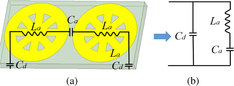
Figure 5: Circuit model of the AMC.
Figure 6 (a) shows the curve of AMC reflection phase changing with the thickness of medium layer hamc. It can be seen that with the increase of the dielectric plate height, the slope of the reflection phase curve becomes smaller, and the central resonant frequency moves to the low frequency. This is because the height of the dielectric plate increases, and the equivalent capacitance increases, that is, C becomes larger, so the resonant frequency decreases. Figure 6 (b) shows the curve of AMC reflection phase changing with rectangular branch width parameter a. With the increase of a, the resonant frequency point moves to high frequency, and the slope of the reflection phase curve slowly increases. Figure 6 (c) shows the variation curve of the AMC reflection phase with the radius Ra of the small ring. With the increase of Ra, the equivalent inductance L of the patch itself increases, the resonant frequency decreases, and the slope decreases slowly. When Ra=5.5 mm, the resonant frequency is closest to the center frequency, and the reflection phase bandwidth is larger. Figure 6 (d) shows the curve of the AMC reflection phase with the radius Rb of the large ring. With the increase of Rb, the equivalent gap capacitance Cincreases, the resonant frequency decreases and the in-phase reflection phase bandwidth decreases. When Rb=7.4 mm, the frequency corresponding to the 0 reflection phase appears at 5.5 GHz, so the value of the parameter Rb is finally chosen to be 7.4 mm. Thus, the resonant frequency of this AMC can be adjusted by changing the values of hamc, Ra, Rb, and a.
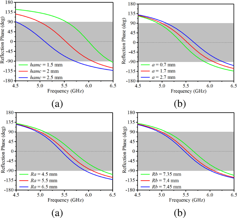
Figure 6: The influence of different parameters on AMC reflection phase.
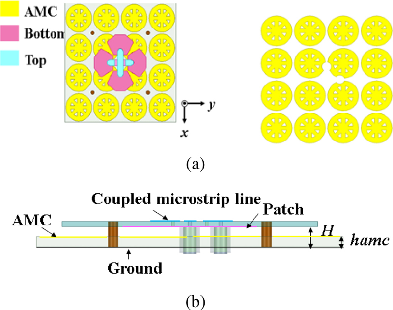
Figure 7: The overall structure of the antenna: (a) top view and (b) side view.
Figure 7 shows the overall structure of the dipole antenna loaded with AMC. The AMC is located 2 mm below the crossed dipole antenna, the total height of the antenna is 5.016 mm, and it is about 0.09 at 5.5 GHz. After simulation and optimization, the final dimensions of the proposed dipole antenna are listed in Table 1.
Table 1: Dimension of the proposed dipole antenna (unit: mm)
| Parameter | Value | Parameter | Value | Parameter | Value |
| L | 50 | R1 | 2.4 | S | 15 |
| W1 | 6 | L1 | 7.2 | Ra | 4.5 |
| W2 | 0.6 | L2 | 14 | Rb | 7 |
| W3 | 3.5 | L3 | 5.4 | a | 1.8 |
| W4 | 3 | L4 | 3 | H | 4 |
| hamc | 2 |
IV. CROSS DIPOLE ANTENNA WITH AMC
In order to verify the performance of the antenna, a low profile dual-polarized antenna loaded with AMC is fabricated, as shown in Fig. 8. Figure 9 is the simulation and measured S-parameter diagram, and the measured results are in good agreement with the simulation results. The common impedance bandwidth is 4.75-6.12 GHz (25.2%), and the isolation is less than -14 dB. Figure 10 shows the simulation and measured gain and radiation efficiency of the antenna. The radiation efficiency exceeds 83% in the frequency band, and the maximum peak gain reaches 10.6 dB. At the central frequency, the gain of 5.5 GHz reaches 9.46 dBi. Good radiation characteristics are maintained in the whole frequency.
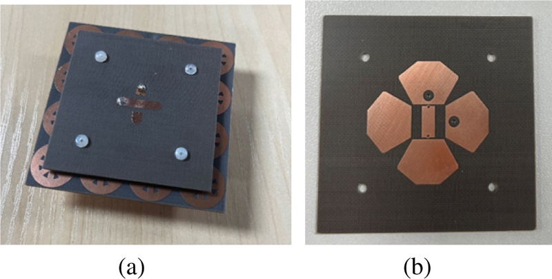
Figure 8: Fabricated antenna loaded with AMC: (a) overall structure drawing and (b) dipole patch layer.
In order to verify the effectiveness of the AMC structure, the cross dipole antenna Ant-AMC loaded with AMC is compared with the cross dipole antenna Ant-PEC loaded with PEC. PEC reflector and AMC reflector have the same size, both of which are 60 60 mm, and the distance from both to the cross dipole radiator is 2 mm. The vertical and horizontal polarized radiation patterns of this antenna at 4.8 GHz, 5.5 GHz and 6 GHz are given in Fig. 11. From the figure, it can be seen that the antenna achieves good forward radiation with both the back lobe less than -10 dB and the cross-polarisation less than -20 dB. The spatial radiation patterns are slightly asymmetric, which is mainly due to the asymmetric placement of the feed position and the current imbalance between the two arms of the dipole caused by the coaxial feed. Figure 12 shows the comparison results of different antennas in S, S, gain and radiation efficiency (Port 1). The specific values are listed in Table 2.
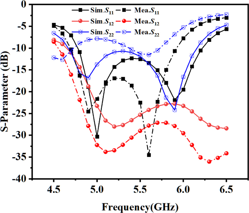
Figure 9: Simulated and measured result of S-parameters.
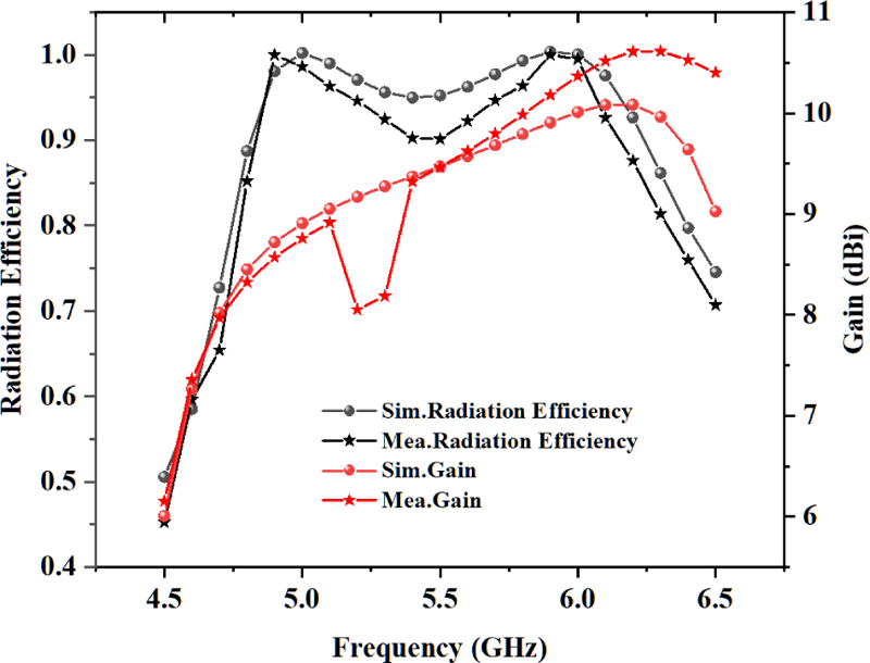
Figure 10: Simulated and measured result of gain and radiation efficiency.
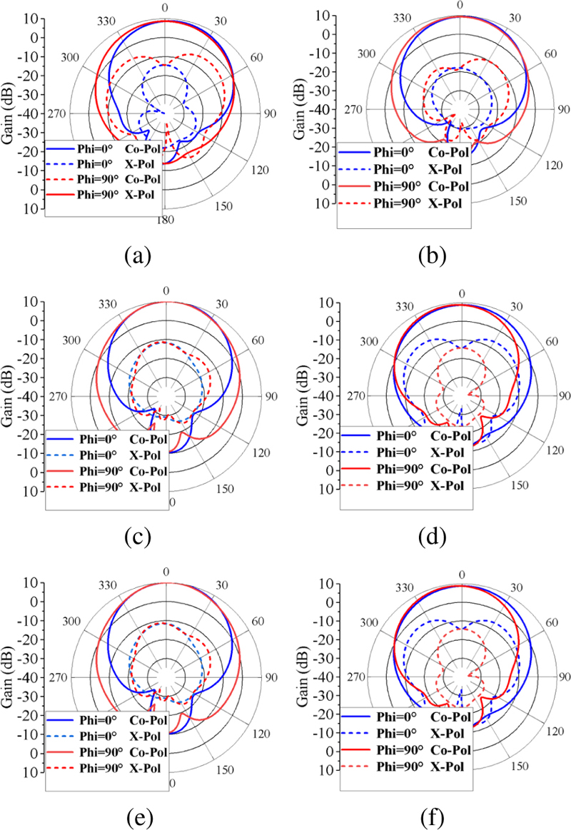
Figure 11: Measured radiation patterns: (a) Port 1 -4.8 GHz, (b) Port 1 -5.5 GHz, (c) Port 1 -6 GHz, (d) Port 2 -4.8 GHz, (e) Port 2 -5.5 GHz, and (f) Port 2 -6 GHz.
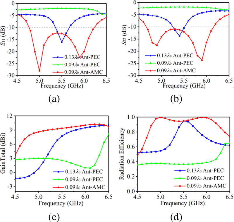
Figure 12: Performance comparison results: (a) S, (b) S, (c) gain total, and (d) radiation efficiency.
Table 2: Comparison results of different antennas
| Antenna | Port 1 BW/GHz | Port 1 BW/GHz | Port 1 Peak Gain/dBi | Efficiency (%) |
| 0.13 Ant-PEC | 5.36-5.67 | 5.25-5.52 | 10 | 60-94 |
| 0.09 Ant-PEC | - | - | 8 | 35-65 |
| 0.09 Ant-AMC | 4.77-6.23 | 4.66-6.16 | 10.3 | 80-99 |
At the central frequency point, the antenna is improved from PEC loaded structure to AMC loaded structure, and the section size of the antenna is reduced from 0.13 to 0.09. With the profile height is reduced to 0.09, the S-parameter curve deteriorates sharply in the required frequency band, and the gain and radiation efficiency under horizontal polarization mode also decrease accordingly.
It can be seen from Table 2 that the peak gain of the three antennas when excited at Port 1 has little change. After the introduction of AMC structure, it can be seen from Fig. 12 (c) that the antenna gain is significantly improved in the whole operating frequency band. At the same time, the radiation efficiency curve of the antenna loaded with AMC is also above the others. Through performance comparison, it is found that the AMC structure proposed in this paper can significantly reduce the profile height of the antenna, improve the working bandwidth of the antenna, and enhance the gain and radiation efficiency of the antenna.
Table 3 shows the comparison results of the working bandwidth and profile height between the antenna designed in this paper and the existing AMC based dual-polarized antenna. Compared with [6], [12] and [13], the proposed dual-polarized antenna has wider bandwidth, but the profile is higher than that of [13]. Compared with [6], [12], [13], and [14], the dual-polarized antenna proposed in this paper has higher gain.
Table 3: Comparison of the antenna with some existing work
| Ref. | Bandwidth | Height () | Peak Gain (dBi) |
|---|---|---|---|
| [6] | 11.4% | 0.21 | 7 |
| [12] | 15.6% | 0.09 | 7.2 |
| [13] | 11.7% | 0.06 | 7.2 |
| [14] | 20.5% | 0.056 | 4.25 |
| Pro. | 25.2% | 0.09 | 10.6 |
V. CONCLUSION
In this paper, a broadband dual-polarized coupling feed dipole antenna based on artificial magnetic conductor is designed, optimized and analyzed. The profile height of the proposed dual-polarized dipole antenna is 0.09, and the antenna uses coupling feed to excite the dipole radiation patch, and the impedance bandwidth reaches 25.2%. The proposed antenna has the advantages of dual-polarization, low profile, broadband. It has great application potential in C-band radar communication and satellite communication.
ACKNOWLEDGMENT
This work was supported by fund of Nationa Mobile Communications Research Laboratory, Southeast University (No. 2023D05), Enterprise entrusted project (W2021JSKF0153, W2020JSFW0112), HeFei University of Technology teacher program (JZ2019HGTB0093), Anhui Natural Science Foundation (2208085MF161), the Fundamental Research Funds for the Central Universities (JZ2021HGTA0144), and the Natural Science Foundation of Anhui Province (No. JZ2022AKZR0453).
REFERENCES
[1] Y. Li, Z. Zhang, W. Chen, Z. Feng, and M. F. Iskander, “A dual-polarization slot antenna using a compact CPW feeding structure,” IEEE Antennas and Wireless Propagation Letters, vol. 9, pp. 191-194, 2010.
[2] Z. Wang, G.-X. Zhang, Y. Yin, and J. Wu, “Design of a dual-band high-gain antenna array for WLAN and WiMAX base station,” IEEE Antennas and Wireless Propagation Letters, vol. 13, pp. 1721-1724, 2014.
[3] P. Kumar, S. Dwari, R. K. Saini, and M. K. Mandal, “Dual-band dual-sense polarization reconfigurable circularly polarized antenna,” IEEE Antennas and Wireless Propagation Letters, vol. 18, no. 1, pp. 64-68, Jan. 2019.
[4] A. P. Feresidis, G. Goussetis, Shenhong Wang, and J. C. Vardaxoglou, “Artificial magnetic conductor surfaces and their application to low-profile high-gain planar antennas,” IEEE Transactions on Antennas and Propagation, vol. 53, no. 1, pp. 209-215, Jan. 2005.
[5] D.-Z. Zheng and Q.-X. Chu, “A wideband dual-polarized antenna with two independently controllable resonant modes and its array for base-station applications,” IEEE Antennas and Wireless Propagation Letters, vol. 16, pp. 2014-2017,2017.
[6] Z.-Y. Zhang and K.-L. Wu, “A wideband dual-polarized dielectric magnetoelectric dipole antenna,” IEEE Transactions on Antennas and Propagation, vol. 66, no. 10, pp. 5590-5595, Oct. 2018.
[7] L.-H. Wen, S. Gao, Q. Luo, Q. Yang, W. Hu, Y. Yin, X. Ren, and J. Wu, “A compact wideband dual-polarized antenna with enhanced upper out-of-band suppression,” IEEE Transactions on Antennas and Propagation, vol. 67, no. 8, pp. 5194-5202, 2019.
[8] C. Zhou, H. Wong, and L. K. Yeung, “A wideband dual-polarized inductor-end slot antenna with stable beamwidth,” IEEE Antennas and Wireless Propagation Letters, vol. 17, no. 4, pp. 608-612, Apr. 2018.
[9] S.-G. Zhou, P.-K. Tan, and T.-H. Chio, “Low-profile, wideband dual-polarized antenna with high isolation and low cross polarization,” IEEE Antennas and Wireless Propagation Letters, vol. 11, pp. 1032-1035, 2012.
[10] M. Li, M. Y. Jamal, C. Zhou, L. Jiang, and L. K. Yeung, “A novel dipole configuration with improved out-of-band rejection and its applications in low-profile dual-band dual-polarized stacked antenna arrays,” IEEE Transactions on Antennas and Propagation, vol. 69, no. 6, pp. 3517–3522, June 2021.
[11] H. R. Raad, A. I. Abbosh, H. M. Al-Rizzo, and D. G. Rucker, “Flexible and compact AMC based antenna for telemedicine applications,” IEEE Transactions on Antennas and Propagation, vol. 61, no. 2, pp. 524-531, Feb. 2013.
[12] H. Zhai, K. Zhang, S. Yang, and D. Feng, “A low-profile dual-band dual-polarized antenna with an AMC surface for WLAN applications,” IEEE Antennas and Wireless Propagation Letters, vol. 16, pp. 2692-2695, 2017.
[13] H. Yang, X. Liu, Y. Fan, and L. Xiong, “Dual-band textile antenna with dual circular polarizations using polarization rotation AMC for off-body communications,” IEEE Transactions on Antennas and Propagation, vol. 70, no. 6, pp. 4189-4199, June 2022.
[14] W. Yang, W. Che, H. Jin, W. Feng, and Q. Xue, “A polarization-reconfigurable dipole antenna using polarization rotation AMC structure,” IEEE Transactions on Antennas and Propagation, vol. 63, no. 12, pp. 5305-5315, Dec. 2015.
BIOGRAPHIES

Zhaoneng Jiang was born in Xuancheng, China. He received the Ph.D. degree from Nangjing University of Science and Technology, Nanjing, China, in 2012. Since 2013, he has worked on the numerical method of computational electromagnetism. He is currently a Professor with the Hefei University of Technology, Hefei, China. He has authored or coauthored more than 90 papers in refereed international conferences and journals and has served as Program Committee Member in several international conferences. Currently, he is focusing on antenna and microwave device.

Zhiwei Li was born in Xuancheng, China. He received his master’s degree from Hefei University of Technology, Hefei, China, in 2023. Since 2020, he has worked on electromagnetic metasurfaces and vortex electromagnetic waves.

Zhixin Wang was born in Anhui, China. She received her master’s degree in electronic communication from Hefei University of Technology in 2022. Currently, she is focusing on antenna and microwave device.
ACES JOURNAL, Vol. 39, No. 1, 17–23
doi: 10.13052/2024.ACES.J.390103
© 2024 River Publishers