High-isolation Wi-Fi Antenna System based on Metamaterial
Zhihao Chen, Ziqin Wang, Fangyuan Chen, Xi Hou, Yonghong Zhou, and Lam Phav
1School of Electronic Information Engineering
Xihua Normal University, Nanchong, Sichuan Province, 637000, China
2Jinyichang Science and Technology Co., Ltd.
Jiaxing, Zhejiang Province, 314000, China
fangyuanscu@gmail.com
3School of Higher Vocational & Technical Teachers
China West Normal University, Nanchong, Sichuan Province, 637000, China
4Ministry of Post and Telecommunications of Cambodia
Khan Daun Penh, Phnom Penh, 120210, Cambodia
Submitted On: April 27, 2023; Accepted On: June 27, 2023
ABSTRACT
In this research, an inverted L shaped Wi-Fi antenna with a metamaterial (MTM) decoupling unit is proposed. This swirly-shaped antenna has a compact geometry size of 0.1 wavelength. The metamaterial decoupling unit is placed between the antenna elements to improve the isolation to reduce the mutual coupling. The antenna’s isolation reached 20.7 dB from 2.4 GHz to 2.48 GHz, and 23.5 dB from 5.15 GHz to 5.85 GHz, after the metamaterial unit was introduced. This designed methodology reinforced the anti-interference capability. This compact and low-cost antenna is especially suitable for application in high-density Wi-Fi 6 systems.
Index Terms: decoupling, miniaturization, metamaterial, Wi-Fi.
I. INTRODUCTION
Wi-Fi technology is extensively employed in wireless communication, especially in the IoT (Internet of Things) system. MIMO (multiple-input multiple-output) technology is widely used in Wi-Fi systems, it enables the communication between the multiple access point and routers. The increasing antenna elements and miniaturization requirement is a contradiction of the antenna’s high isolation requirement.
The common-mode theory and differential-mode theory are a widely used method to solve the antenna coupling problem. The isolation problem can be reduced by introducing two filters. While this method works on the circuit, it does not eliminate the coupling problem fundamentally [1]. The neutral line method is also widely employed in reducing the coupling effect, by introducing the cancellation effect within antenna elements [2–4]. Also, in Luo’s study, the metamaterial unit is applied to alleviate the electromagnetic wave leak between the transmitting antenna and receiving antenna. The isolation improved by approximately 30 dB in this study. At present, there are many research papers on decoupling of Wi-Fi frequency bands [5–7]. However metamaterial is rarely employed in Wi-Fi systems.
In Ramya’s study, a triple-band metamaterial absorber is introduced to reduce the radar cross-section problem [8]. In Almirall’s study, a novel wearable metal material with high isolation ability is studied [9]. In Vosoughitabar’s study, a novel two-dimensional time-modulated metamaterial transmitter is proposed, this design guaranteed a low bit error rate in an orthogonal frequency division multiplexingsystem [10].
Metamaterial is widely used in antenna design as well. Due to the negative refractive index properties of metamaterial, it is frequently employed in the improvement of the antenna’s gain [11–13]. In Jha’s paper [14], metamaterial is used to increase the operating bandwidth and reduce antenna sizes, and the electrical length is only 0.14*0.21. In Singh’s paper, a transmissive metamaterial is proposed as a planar lens, allowing microstrip antennas working on the metamaterial to improve gain by 8.55 dB in the H-plane and 6.20 dB in the E-plane at 10 GHz, respectively [15]. Zhang proposed a metamaterial array loaded with C-type on a dipole antenna to enable the gain improvement in the demanded frequency band. Metamaterial is also employed in microwave devices and transmission line design to reduce return loss [16].
In this research, a novel compact Wi-Fi antenna with an inverted L shape is proposed. The following contributions and novel areas are analyzed:
1. A smaller metamaterial structure is used to improve the isolation of the MIMO antenna.
2. The use of a CPW (coplanar waveguide) feed, which is easier to integrate into the equipment, and can reduce the dispersion effect.
3. The proposed antenna with a compact geometry size, with a mere 0.2*0.2 size.
4. The FR4 dielectric substrate is used, which is low cost and is suitable for mass production.
5. The proposed antenna is suitable for Wi-Fi communication systems.
II. GEOMETRY AND CHARACTERIZATION OF ANTENNA
Figure 1 shows the antenna structure. The symmetric Wi-Fi radiation unit is located on the margin of the ground, the metamaterial unit is located between the radiation unit. The radiation unit and the metamaterial unit are parallel and vertical to the ground, which facilitates the soldering. The coupling waveguide is applied as the exciting port.
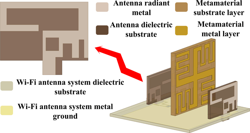
Figure 1: Geometry structure of the antenna.
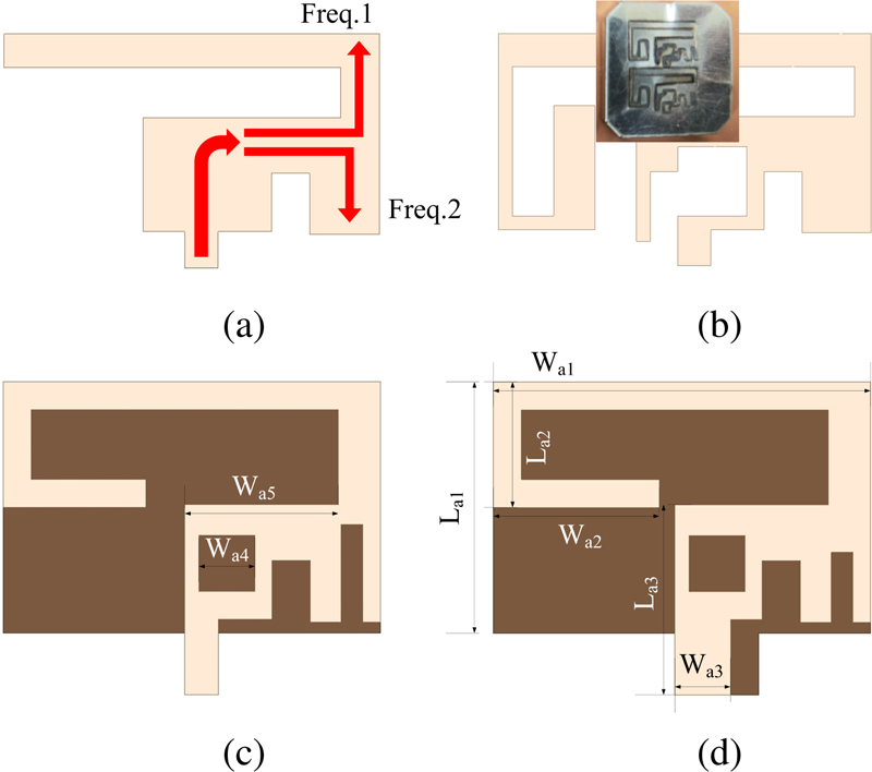
Figure 2: Antenna evolution and the Wi-Fi antenna structure size: (a) Step 1, (b) Step 2, (c) Step 3, and (d) Step 4.
The Wi-Fi antenna is 9.513.50.8 mm in size. FR4 (with a dielectric 4.4 and loss tangent 0.019) is employed for the antenna, MTM, and GND (ground). As shown in Fig. 2 (a), parasitic branches are placed on the Wi-Fi antenna to achieve dual-band communication, based on two different lengths of radiation branches to achieve resonance at 2.4 GHz and 5 GHz. Considering that the resonant cavity size of the planar antenna is large, the process of adjusting the resonance point and impedance matching is difficult, thus the inverted L antenna (ILA) is introduced in mobile devices due to its low cost and low profile. This design was inspired by the methodology from Tae [17].
As shown in Fig. 2 (b), the slot and bent structure are difficult to process due to the flexibility of the iron sheet. Meanwhile, the intrinsic impedance characteristic of iron has an apparent influence on electromagnetic radiation. Thus, the microstrip structure is employed, as shown in Fig. 2 (c). The structure is elaborately designed to achieve the required communication band. For the convenience of mass production and installation, Parameter W and antenna dielectric substrate geometry size are optimized, as shown in Fig. 2 (d). The E-shape metal patch lies on the right corner of the ground to expand the working frequency [18]. To achieve 2.4 GHz resonance in a compact size, the microstrip line is bent at the top left of the dielectric substrate to increase the electrical current length. The width of the coplanar waveguide and its gap distance is optimized based on the 2.4 GHz band to achieve the impedance match. The optimized parameters of the Wi-Fi antennas are W= 13.5 mm, W= 5.9 mm, W= 2 mm, W= 2 mm, W= 5.5 mm, L= 9 mm, L= 4.5 mm, L= 6.8 mm.
III. METAMATERIAL STRUCTURE AND THEORETICAL ANALYSIS
A. Theoretical analysis
Metamaterial is a kind of special artificial material, with equivalent negative permeability or dielectric constant. The performance of metamaterials mainly depends on the overall structure, size, dielectric thickness, incidence angle of excitation, electromagnetic wave, etc. This character empowers its geometry size which can be much more compact than the working frequency band [19]. Electromagnetic propagation in metamaterial is different from conventional material. Based on equation (1), the dot product of space electromagnetic wave propagation directionand wave vector directiongives a negative number when the permittivityand permeabilityare less than zero. Thus the electromagnetic wave propagation direction and energy flow are in opposite directions in a specific frequency band under a specific metamaterial structure, from the time-harmonic electromagnetic wave theory.
| (1) |
Figure 3 displays the interference of the metamaterial to the electromagnetic wave propagation. The metamaterial can absorb and reflect wave energy in a certain condition. This character can be employed to improve antenna isolation. Based on the microwave theory [20], the refractive index and impedance can be expressed with the S-parameters:
| (2) | ||||
| (3) |
The refractive index and impedance can be obtained from the S parameters in a tow-port network, from equations (4) and (5), permittivity, permeability, and impedance with the following relationship:
| (4) | |||
| (5) |
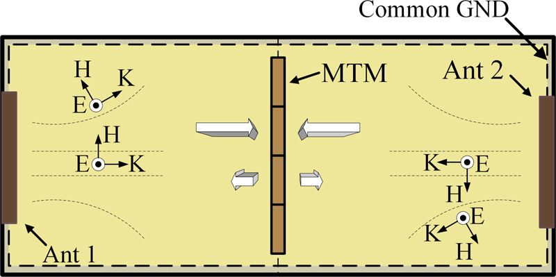
Figure 3: Wi-Fi antenna system electromagnetic wave coupling schematic.
When the propagation medium is a single negative material, as shown in equation (6), the refractive index is equivalent to a pure imaginary number, which proves that electromagnetic waves cannot propagate in this medium material.
| (6) |
B. Metamaterial structure
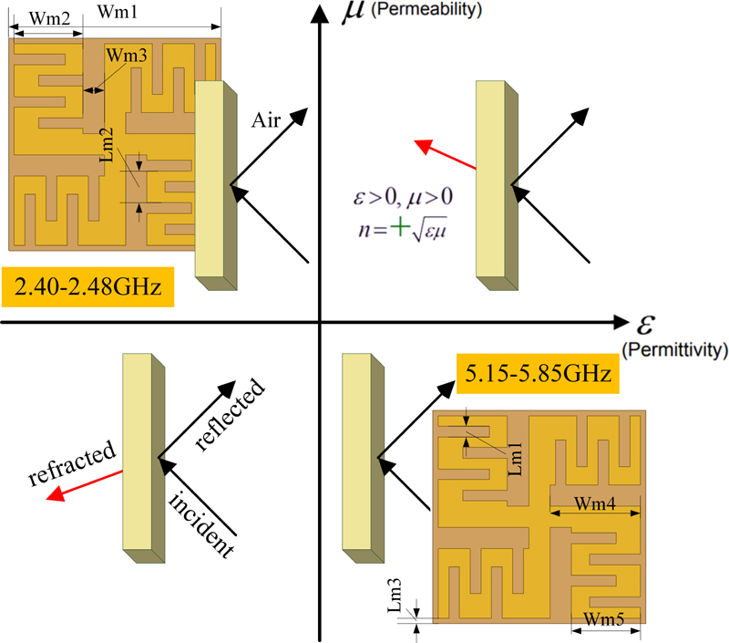
Figure 4: Structure and properties of metamaterials.
Figure 4 shows the metamaterial unit. The metal patch on the material unit is in a finger cross shape, and in a central symmetric shape. In order to reduce the overall size of the metamaterial as much as possible, this design prints the same metamaterial metal layer on both sides of the metamaterial dielectric substrate to increase the gap and branch loading. The metal layer is on both sides of the 0.8 mm FR4 substrate. When the permittivity or permeability’s value is smaller than zero, that is in the second coordinate or in the fourth coordinate, the metamaterial can absorb energy, as shown in Fig. 4.
As shown in Fig. 5, the metamaterial unit needs to be placed in a waveguide environment simulated by ANSYS Electronics. The boundary conditions of the waveguide model require that the upper and lower surfaces along the electric field direction are set as perfect electric wall (PEC), the front and rear surfaces along the magnetic field direction are set as perfect magnetic wall (PMC), and the left and right surfaces along the wave propagation direction are set as wave port excitation. It can be found that the obtained S21 is lower than -10 dB in the operating frequency band (2.4-2.48/5.15-5.85 GHz), and has obvious stop bandcharacteristics.
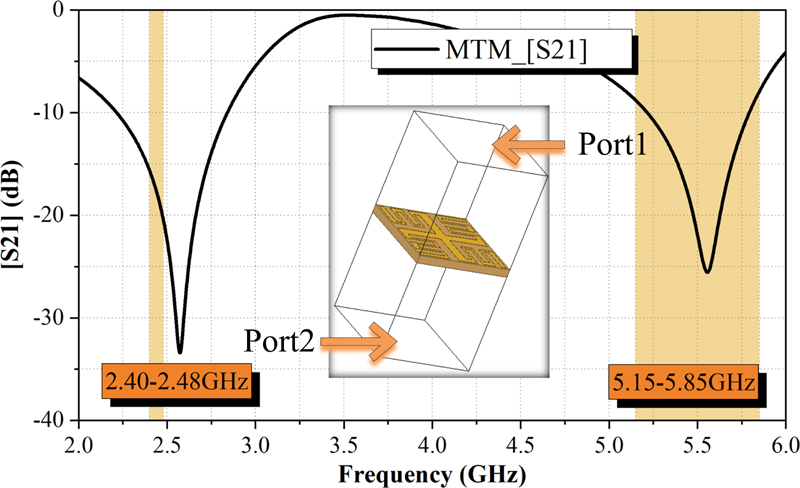
Figure 5: MTM stop band characteristics.
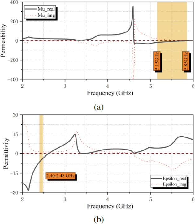
Figure 6: (a) Metamaterial equivalent permeability (real part and imaginary part) and (b) Metamaterial equivalent dielectric constants (real part and imaginary part).
As shown in Fig. 6, after obtaining the S-parameters of the two-port metamaterial cell based on the Finite Integration Technique, the transformation matrix method is then used to derive the permeability and permittivity. In this design, the permittivity is smaller than zero from 2.4 GHz to 2.48 GHz, and the permeability is smaller than zero from 5.15 GHz to 5.85 GHz. In these two frequency bands, the metamaterial belongs separately to ENG (Epsilon Negative) and MNG (Mue-Negative) media, respectively. It can be proved, based on equation (6), that a specific frequencies wave cannot propagate in the media. So, in theory the material can absorb the electromagnetic wave in the corresponding frequency band and improve the antenna isolation level. The optimized parameters of the metamaterial are W = 20 mm, W = 5.8 mm, W = 2 mm, W = 8.5 mm, W = 6.5 mm, L = 1.4 mm, L = 2.6 mm, L = 0.5 mm.
IV. PARAMETERS ANALYSIS
In this study, the inverted L-bent branches are considered as a basic design structure. The equivalent capacity between the antenna branch and the ground needs to be reduced to ensure good radiation performance at low-frequency band. As shown in Fig. 7, the S is reduced when L gets smaller. The return loss performance at 2.44 GHz reached the requirement when L is 4.5 mm.
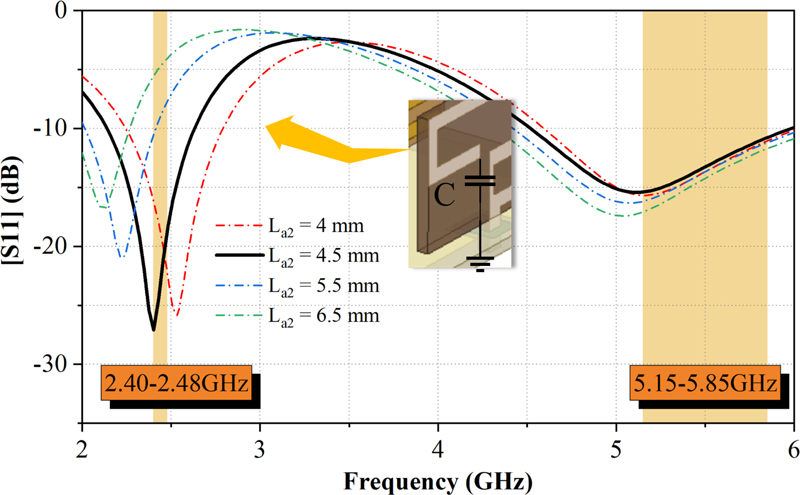
Figure 7: Simulated S from different geometry size L-bent branches.
The isolation performance in the condition of the metamaterial unit and metal layer are compared. As shown in Fig. 8, the S is -11.6 dB at 2.4 GHz in the absence of metamaterial, and S is larger than -20 dB. Between 5.15 GHz and 5.85 GHz, the isolation improves after the metal layer is introduced in the middle of the antenna while the isolation at the lower frequency band gets larger. The isolation is smaller than -20 dB both in the lower frequency and higher frequency after the metal material unit is introduced. So this designed metamaterial unit has a positive effect in reducing the electromagnetic wave coupling effect.
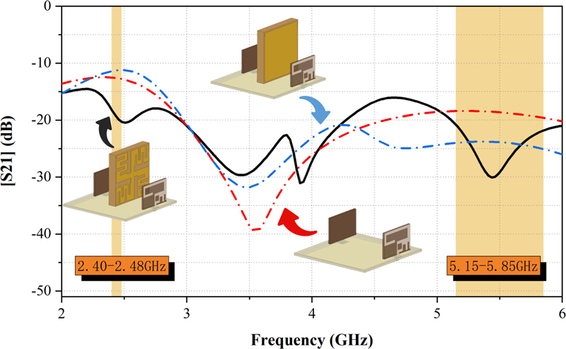
Figure 8: Simulated S about comparing metamaterial unit and metal baffle.
The antenna can be regarded as a combination of a curve-type capacitance and inductance [21]. The metamaterial structure is optimized to ensure the best performance in the improvement of antenna isolation. As shown in Fig. 9, the center working frequency is left-shifted with the increase of W. S has the best performance when W is 4.8 mm. As shown in Fig. 4, the overall inductance increases when W gets larger, thus the resonance frequency band is left-shifted. In this study, a metal layer is optimized to improve the metamaterial performance, this methodology improves the isolation at low frequencies in a limited space with great value to the MIMO antenna design.
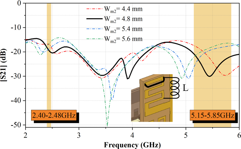
Figure 9: Simulated S from different geometry size W-bent branches.
V. RESULTS AND ANALYSIS
The simulated and measured VSWR(voltage standing wave ratio)of these two Wi-Fi antennas are shown in Fig. 10. These two curves with a great agreement with each other, but with a small discrepancy. This discrepancy is from the testing error and manufacturing. The frequency band in the condition of VSWR3 covers the entire Wi-Fi bands for the measured results. As shown in Fig. 11, the isolation drops from -8 dB to -19.3 dB at 2.4 GHz when the metamaterial is introduced and placed at the adjusted position. The isolation at higher Wi-Fi frequency drops from -16.6 dB to -18.2 dB, this value satisfies the requirement of -15 dB in engineering applications.
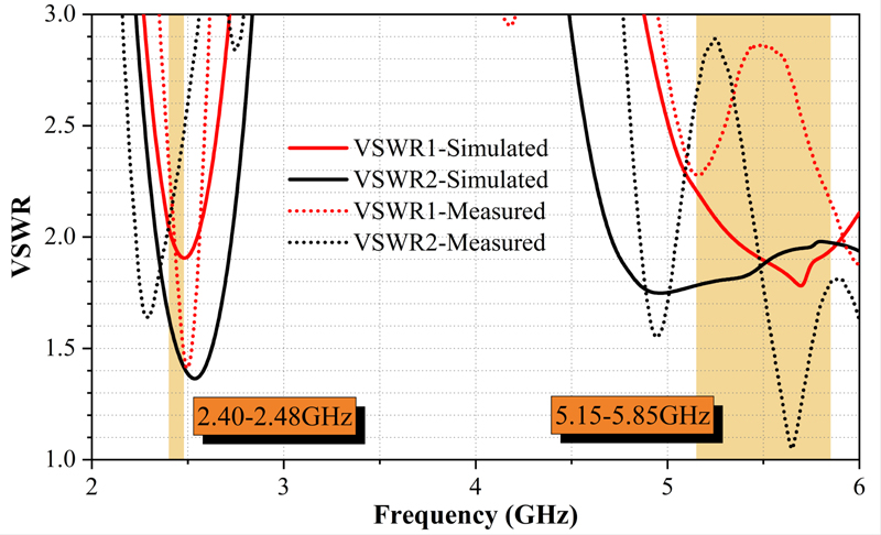
Figure 10: Simulated and measured VSWR.
As shown in Fig. 12, the simulated and measured antenna working efficiency is higher than 79%. The maximum antenna gain is 6 dBi at 2.4 GHz, and 8 dBi at 5 GHz. This is an excellent performance for an electric small antenna. We used a SATIMO multi-probe near-field antenna measurement system as shown in Fig. 13, which is different from traditional far-field measurement systems. It provides faster and more accurate test results. The radiation pattern is measured in a 5m5m5m specially designed near-field anechoic chamber with 24 near-field EM probes for antenna device testing.
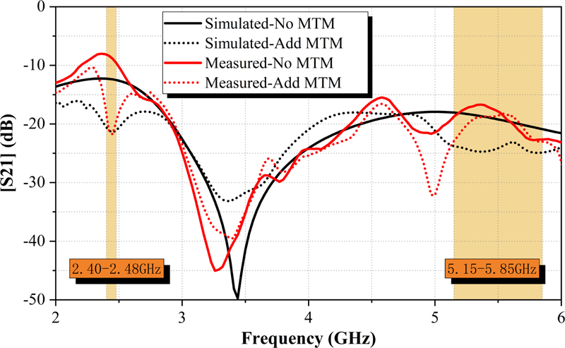
Figure 11: Simulated and measured antenna isolation.
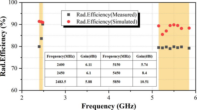
Figure 12: Measured and simulated antenna efficiencies and gain.
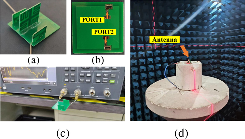
Figure 13: Antenna and the testing environment (a) antenna, (b) antenna feed position, (c) reflection coefficient test with vector network analyser, and (d) antenna measurement in the microwave anechoic chamber.
Figure 14 shows the antenna radiation performance of the E plane and H plane, both at 2.45 GHz and 5.4 GHz. This antenna is tested in a near-field microwave anechoic chamber, with 32 microwave probes. It can be seen this antenna system is omnidirectional and has a good radiation characteristic.
The corresponding relation between ECC(Envelop Correlation Coefficien) and frequency of the two-port MIMO antenna system proposed in this paper is shown in Fig. 15. It can be seen that at the operating frequency, the ECC parameter is lower than 0.2, which is considered as the optimal performance of the MIMO antenna in engineering.
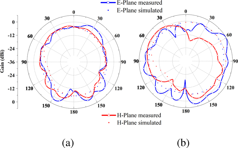
Figure 14: Measured and simulated radiation patterns: (a) 2450 MHz and (b) 5400 MHz.
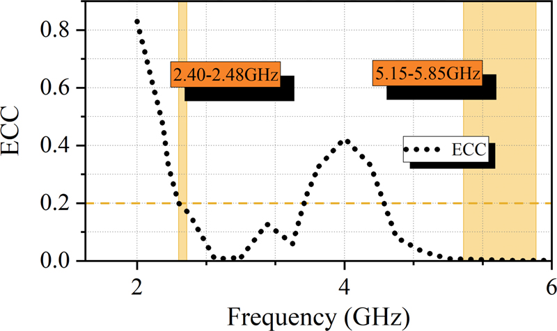
Figure 15: The tested ECC at work frequency band.
Table 1: Performances comparison with relevant studies
| Ref | Distance (mm) |
Number of Antennas | Working Frequency Band | Isolation (dB) |
| [22] | 35 mm (0.28 ) | 2 | 2.40-2.48 GHz | -17.9 dB |
| [23] | 25 mm (0.08 ) | 2 | 1-25 GHz | -10 dB |
| [24] | 20 mm (0.16 ) | 4 | 2.40-2.69 GHz/3.4-3.69 GHz | -10 dB |
| [25] | 30 mm (0.34 ) | 4 | 3.4-3.7 GHz | -10 dB |
| [26] | 40 mm (0.43 ) | 2 | 3.2-3.8 GHz/5-6.8 GHz | -18 dB |
| [27] | 48 mm (0.44 ) |
8 | 3.3-6 GHz | -11 dB |
| Prop. | 25 mm (0.2 ) | 2 (without metamaterial) | 2.40-2.48 GHz/5.15-5.85 GHz | -8 dB |
| 25 mm (0.2 ) | 2 (with matematerial) | -19.3 dB |
As shown in Table 1, the proposed Wi-Fi antenna in this research has better isolation compared with previous studies. This MIMO antenna’s frequency covers the entire Wi-Fi band, and with vertical placement. This design elaborately utilizes a small space and has guaranteed vertical polarization performance.
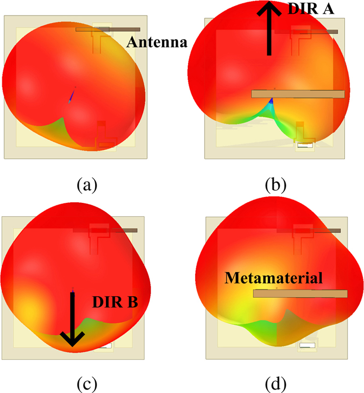
Figure 16: Measured 3D radiation patterns: (a) no MTM in 2450 MHz MTM, (b) with MTM in 2450 MHz, (c) no MTM in 5400 MHz, and (d) with MTM in 5400 MHz.
Figure 16 compares the influence of metamaterial structure on the radiation pattern of Wi-Fi antenna. It can be seen that the radiation intensity in direction A at 2.4 GHz is increased to a certain extent after the introduction of the metamaterial structure. The antenna radiation intensity is decreased in direction B at frequency 2450 MHz and 5400 MHz, which conforms to the characteristics of the ENG (Epsilon Negative) dielectric and the MNG (Mue-Negative) dielectric. So it is derived that the electromagnetic wave cannot propagate in thetwo media.
VI. CONCLUSION
In this work, a high isolation co-ground and dual band Wi-Fi antenna based on metamaterial is proposed. The isolation in the Wi-Fi frequency band improved with the introduction of the proposed material and verified the effectiveness of the proposed metamaterial absorber. This design solved the microwave interference problem of the MIMO antenna. This design methodology also works on the antenna decoupling system. This antenna is compact, with a 303020 mm size, and with a simple feeding method. In addition, the antenna has high radiation efficiency ( 79%) and high isolation (S -16 dB) so is very suitable for application in Wi-Fi devices.
ACKNOWLEDGMENT
This work is supported by the Nanchong Key Laboratory of Electromagnetic Technology and Engineering. Jinyichang Science and Technology Co. Ltd. provided the hardware support, technical assistance, and the test environment.
REFERENCES
[1] W. Zhang, Y. Li, K. Wei, and Z. Zhang, “A two-port microstrip antenna with high isolation for Wi-Fi 6 and Wi-Fi 6E applications,” IEEE Transactions on Antennas and Propagation, vol. 70, no.7, pp. 5227-5234, Jan. 2022.
[2] R. Liu, X. An, H. Zhang, M. Wang, Z Gao, and E. Lei, “Neutralization line decoupling tri-band multiple-input multiple-output antenna design,” IEEE Access, vol. 8, pp. 27018-27026, Feb. 2020.
[3] D. Saxena, A. Kumar, R. K. Verma, and P. Jha “Metamaterial inspired dual band MIMO antenna with open-ended slot and neutralized line for isolation enhancement,” IEEE 10th International Conference on Signal Processing and Integrated Networks (SPIN), Noida, India, pp. 727-732, May 2023.
[4] A. Kumar, C. Tyagi, D. Saxena, and P. Jha, “Miniaturized two-element MIMO antenna with neutralization line and an asymmetric open slot for WLAN and IOT applications,” IEEE International Conference on Artificial Intelligence and Smart Communication (AISC), Greater Noida, India, pp. 227-231, Apr. 2023.
[5] P. Jha, A. Kumar, A. De, and R. K. Jain, “Flexible and textile two-port compact antenna for WLAN and wearable applications,” IEEE 8th International Conference on Signal Processing and Integrated Networks (SPIN), Noida, India, pp. 308-311, Aug. 2021.
[6] P. Jha, A. Kumar, A. De, and R. Jain, “Two-port miniaturized textile antenna for 5G and WLAN applications,” International Journal of Microwave and Wireless Technologies, pp. 1-10, Apr. 2023.
[7] A. Kumar, D. Saxena, P. Jha, and N. Sharma, “Parasitic and open slot-based circular polarized two-port antenna for ISM applications,” IEEE International Conference on Artificial Intelligence and Smart Communication (AISC), Greater Noida, India, pp. 332-337, Apr. 2023.
[8] S. Ramya and I. S. Rao, “Design of new metamaterial absorber with triple band for radar cross section reduction,” IEEE Fifth International Conference on Advances in Computing and Communications (ICACC), Kochi, India, pp. 303-306, Mar. 2015.
[9] O. Almirall, R. Fernández-García, and I. Gil, “Wearable metamaterial for electromagnetic radiation shielding,” The Journal of the Textile Institute, vol. 113, no. 8, pp. 1586-1594, June 2021.
[10] S. Vosoughitabar, A. Nooraiepour, W. Bajwa, N Mandayam, and C. Wu, “Metamaterial-enabled 2D directional modulation array transmitter for physical layer security in wireless communication links,” IEEE/MTT-S International Microwave Symposium-IMS, Denver, CO, USA, pp. 595-598,June 2022.
[11] I. U. Din, S. Ullah, S. I. Naqvi, R. Ullah, E. Ali, and M. Alibakhshikenari, “Improvement in the gain of UWB antenna for GPR applications by using frequency-selective surface,” International Journal of Antennas and Propagation, Oct. 2022.
[12] S. Kundu, A. Chatterjee, and S. K. Jana, “Gain enhancement of a printed leaf shaped UWB antenna using dual FSS layers and experimental study for ground coupling GPR applications,” Microwave and Optical Technology Letters, vol. 60, no. 6, pp. 1417-1423, Apr. 2018.
[13] B. Qiu, Y. Xia, and Y. Li, “Gain-enhanced wideband circularly polarized antenna with a non-uniform metamaterial reflector,” Applied Computational Electromagnetics Society (ACES) Journal, vol. 37, no. 3, pp. 281-286, July 2022.
[14] P. Jha, A. Kumar, A. De, and R. K. Verma, “CPW-fed metamaterial inspired compact multiband antenna for LTE/5G/WLAN communication,” Frequenz, vol. 76, no. 7, pp. 401-407, Mar. 2022.
[15] A. K. Singh, M. P. Abegaonkar, and S. K. Koul, “A negative index metamaterial lens for antenna gain enhancement,” 2017 International Symposium on Antennas and Propagation (ISAP), Phuket, Thailand, pp. 1-2, Nov. 2017.
[16] F. Zhang, Q. Wu, and J. C. Lee, “Miniaturized microstrip-based metamaterials quasi-standard transmission lines unit,” IEEE Proceedings of 2012 5th Global Symposium on Millimeter-Waves, Harbin, China, pp. 629-632, May 2012.
[17] H. Tae, K. Oh, W. Son, W. Lim, and J. Yu, “Design of compact dual-band quadruple inverted-F/L antenna for GPS L1/L2 band,” IEEE Transactions on Antennas and Propagation, vol. 61, no. 4, pp. 2276-2279, Apr. 2013.
[18] F. Yang, X. Zhang, X. Ye, and Y. Rahmatsamili, “Wide-band E-shaped patch antennas for wireless communications,” IEEE Transactions on Antennas and Propagation, vol. 49, no. 7, pp. 1094-1100, July 2001.
[19] X. Zhu, X. Yang, Q. Song, and B. Liu, “Compact UWB-MIMO antenna with metamaterial FSS decoupling structure,” EURASIP Journal on Wireless Communications and Networking, vol. 2017, no. 1, pp. 1-6, Dec. 2017.
[20] X. Chen, T. M. Grzegorczyk, B. I. Wu, J. Pacheco, and J. Kong, “Robust method to retrieve the constitutive effective parameters of metamaterials,” Physical Review E, vol. 70, no. 1, July 2004.
[21] L. Kurra, M. P. Abegaonkar, A. Basu, and S. Koul, “FSS properties of a uniplanar EBG and its application in directivity enhancement of a microstrip antenna,” IEEE Antennas and Wireless Propagation Letters, vol. 15, pp. 1606-1609,Jan. 2016.
[22] I. Gil and R. Fernández-García, “Study of metamaterial resonators for decoupling of a MIMO-PIFA system,” IEEE 2016 International Symposium on Electromagnetic Compatibility-EMC EUROPE, pp. 552-556, Sep. 2016.
[23] A. Armghan, K. Aliqab, V. Sorathiya, F Alenezi, M. Alsharari, and F. Ali, “Design and fabrication of the split ring resonator shaped two-element MIMO antenna with multiple-band operation for WiMAX/5G/Zigbee/Wi-Fi applications,” Micromachines, vol. 13, no. 12, pp. 2161-2170, Dec. 2022.
[24] R. Hussain, A. Raza, M. Khan, and M. Sharawi, “Miniaturized frequency reconfigurable pentagonal MIMO slot antenna for interweave CR applications,” International Journal of RF and Microwave Computer-Aided Engineering, vol. 29, no. 9, pp. 11-21, Apr. 2019.
[25] A. Kholapure and R. Karandikar, “Printed MIMO antenna with reconfigurable single and dual band notched characteristics for cognitive radio,” IEEE International Conference on Antenna Innovations & Modern Technologies for Ground, Aircraft and Satellite Applications (iAIM), Bangalore, India, pp. 1-5, Nov. 2017.
[26] R. Verma and A. Kumar, “WI-FI reconfigurable dual band microstrip MIMO antenna for 5G and WI-FI WLAN applications,” Przeglad Elektrotechniczny, July 2021.
[27] J. He, S. Zhu, J. Yu, H. Li, and G. Li, “Wideband decoupled 8-element MIMO mobile phone antenna for sub-6GHz 5G NR bands,” Applied Computational Electromagnetics Society (ACES) Journal, vol. 37, no. 12, pp. 1208-1215, 2022.
BIOGRAPHIES

Zhihao Chen received his B.E. degree in Communication Engineering from China Jiliang University, HangZhou, China, in 2021. Since 2021 he has been pursuing a master’s degree in Electronic Information Engineering, at China West Normal University, Nanchong, China. He was a teaching assistant at the same university. His research interests include microwave theory and technology, and antenna design.

Ziqin Wang received his B.E. degree in Applied Electronic Engineering from China West Normal University, Nanchong, China, in 2020. Since 2021 he has been pursuing a master’s degree in Electronic Information Engineering, at the same university. He was an intern at Jinyichang Science & Technology from 2022 to 2023. His research interests include microwave theory, numerical computation in electromagnetics, and antenna design.

Fangyuan Chen received his Ph.D degree in Radio Physics at Sichuan University, Chengdu, China, in 2016. From 2013 to 2015 he was a visiting doctoral student at Cornell University, New York, USA. Now he is the deputy chief engineer of Jinyichang Science & Technology Co., Ltd. Currently, he is responsible for strategic technology development in V2X network architecture design, multi-band frequency antenna design. His research interests are microwave theory and technology, and optimization algorithms.

Xi Hou is currently pursuing an M.D. degree at the School of Electronic Information Engineering, China West Normal University. She worked on CITIC’s Engineer of Excellence program. Her current research interests include antenna and metasurfaces and their applications.

Yong hong Zhou received his M.S. degree in Computer Applications Technology and his Ph.D. degree in Radio Physics from Southwest Petroleum University and Sichuan University, Chengdu, China, in 2005 and 2017, respectively. He joined the teaching staff in 2005 and is currently a Professor with the School of Electronic Information Engineering, China West Normal University. His research area include microstrip antennas, electromagnetic metasurfaces and their applications, and numerical methods applied in electromagnetics.

Lam Phav received his B.E degree in Computer Science and Engineering, from the Royal University of Phnom Penh, Cambodia, in 2004. He received his M.Sc. degree in Communication Information Systems, from Sichuan University, Chengdu, Sichuan, China, in 2013. Currently he is working at the General Department of Information and Communication Technology, Ministry of Post and Telecommunications (MPTC), Phnom Penh, Cambodia. His research intetrests are antenna theory and design, and wireless communication technology.
ACES JOURNAL, Vol. 38, No. 5, 343–351
doi: 10.13052/2023.ACES.J.380507
© 2023 River Publishers