Wideband Wide-angle SSPP-fed Leaky-wave Antenna withLow Side-lobe Levels
Yanzhen Shi, Zhibo Fan, Cong Chen, and Yongjin Zhou
1Key Laboratory of Specialty Fiber Optics and Optical Access Networks
School of Communication and Information Engineering, Shanghai University, Shanghai 200444, China
yanzhen_shi@163.com, fzbyuuna@shu.edu.cn, yjzhou@shu.edu.cn
2Electronic Information School
Wuhan University, Wuhan 430072, China
chencong@whu.edu.cn
3Shaanxi Key Laboratory of Artificially-Structured Functional Materials and Devices
Air Force Engineering University, Xi’an 710051, China
Submitted On: May 17, 2023; Accepted On: October 15, 2024
ABSTRACT
In this paper, a broadband wide-angle leaky-wave antenna (LWA) with low sidelobe levels (SLL) is proposed. The antenna is composed of two parts: a broadband wide-angle scanning spoof surface plasmon polariton (SSPP)-fed circular patch antenna array and electromagnetic bandgap (EBG) structures tiled on both sides of the antenna array. By controlling the coupling distances between the circular radiation patches and SSPP feeding line, the attenuation constant along the radiation aperture is specially designed in a tapered way to achieve low SLL. EBG structures are adopted to reduce the back-lobe levels. Measured results show that the scanning angle of the proposed antenna reaches 82. The measured realized gains are from 8 to 15.7 dBi in the operating frequency range from 8 to 12 GHz, with a maximum SLL less than -15 dB. The wide-band wide-angle SSPP-fed LWA with low SLL can find applications in radar detection and microwave imaging.
Index Terms: Electromagnetic bandgap (EBG), leaky-wave antenna (LWA), low side-lobe levels (SLL), surface plasmon polaritons (SPP), wide-angle.
I. INTRODUCTION
Leaky-wave antennas (LWAs) typically generate leaky-wave radiation by gradually leaking electromagnetic (EM) energy along the structure, which are often used in radar detection and microwave imaging as a kind of frequency scanning antenna [1, 2]. To detect low altitude, slow speed, and small aircraft targets, LWAs usually require a wide scanning angle. To implement ground clutter suppression, the radar system also requires an antenna with low sidelobe levels (SLL). Spoof surface plasmon polariton (SSPP) refers to surface EM modes formed on the metal surface at microwave and terahertz frequencies [3–6], which can be employed to increase the beam scanning angle of LWAs. Periodically-modulated plasmonic waveguides have been developed to convert SSPPs to radiating waves and achieve frequency scanning antenna radiation from forward to backward directions in [7], which achieved a scanning angle of 18 from 8.5 to 9.8 GHz. An SSPP-fed antenna array enables a larger scanning angle [8, 9]. In [8], an SSPP-fed circular patch array antenna was proposed, achieving a scanning angle of 55 from 5 to 11 GHz. By adopting double-layer coupled SSPP feeding structures, a broader impedance bandwidth and larger scanning angle have been achieved [10, 11]. In [10], a circular patch array antenna fed by SSPP was proposed and implemented a scanning angle of 68 operated in 11-15 GHz. However, the mentioned SSPP LWAs suffer from high SLL (10 dB) when the scanning angle is large.
Different kinds of methods have been proposed and applied to LWAs to reduce SLL, including changing the size of radiating elements [12–14], adjusting the density of radiating elements [15], and controlling the distance between the radiating elements and the feeding line [16–18]. In [12, 13], the leakage amount of the LWA is controlled by changing the length and width of slots, achieving a SLL below -20 dB. A SLL below -15 dB is implemented by adjusting the deviation angle of slots in a transverse slot array antenna [14], but its scanning angle is only 2.9. By changing the density of transverse slots to control the amplitude of the aperture field distribution, a SLL of -20 dB within a scanning range of 31 has been achieved [15]. The most common method is to control the distance between slots or patches and the feeding line to regulate the leakage of EM energy [16–18]. In [17], by controlling the distance between the long slot and via hole arrays, a SLL of -20 dB is achieved within a range of 18.6. Although these works can achieve low SLL, they suffer from a relatively narrow relative bandwidth (30%) and limited scanning range (40).
In this paper, a broadband, wide-angle, and low SLL SSPP-fed LWA is proposed. The SSPP-fed circular patch antenna array’s distinct tapered aperture field distribution effectively reduces the SLL, while the electromagnetic bandgap (EBG) structure evenly dispersed along both sides of the antenna minimizes the back-lobe levels of the antenna. In the operating frequency range from 8 to 12 GHz, the measured scanning angle is 82, with a gain fluctuation from 8 to 15.7 dBi and a maximum SLL less than -15 dB. The frequency beam scanning antenna supports radar detection of low-altitude, slow-speed, and miniaturized targets.
II. ANALYSIS AND DESIGN
A. Design of SSPP antenna
Figure 1 presents the proposed SSPP antenna’s configuration. Theta is defined as the angle between the radiation beam and the z direction and phi is defined as the angle between the radiation beam and the x direction. The antenna is made up of two F4B ( and ) substrate layers (Sub1 and Sub2) and three metallic layers. The SSPP feeding line etched on Sub2 (h 1.5 mm) is shown in Fig. 1 (b). The radiating circular patches are etched on the top of Sub2 (h 0.5 mm) illustrated in Fig. 1 (c). The width of Sub1 and Sub2 is l. The length of Sub1 is 12 mm shorter than Sub2, leaving gaps for welding ports. There are 24 circular radiation patches arranged in a row. The space between adjacent patches is d. The distance between the circular patch’s center and the SSPP line’s bottom is set to d. The period of SPP unit is p. The groove width is a and the depth of SSPP unit is h. Transition parts are arranged between the SSPP units and the microstrip line to achieve an efficient modes transition where the groove depth varies from 0 to h in gradient. The radius r of the circular patch is 4.5 mm, which corresponds to the radius in TM-mode, which can be determined by:
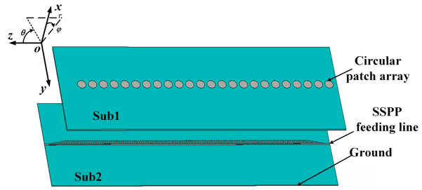
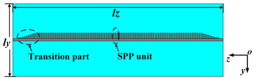
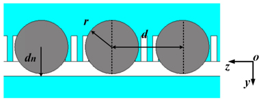
Figure 1: Geometry of the proposed LWA: (a) perspective view, (b) top view of SSPP feeding line layer, and (c) zoomed top view (l 320 mm, l 100 mm, d 12 mm, d 5 mm, r 4.5 mm).
| (1) |
where c is the velocity of light in free space.
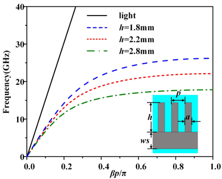
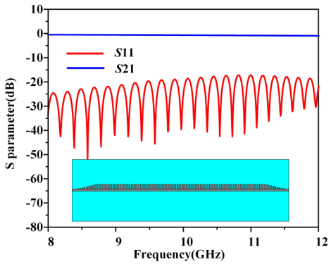
Figure 2: Performance of the SSPP unit and the SSPP transmission line: (a) dispersion curves of the SSPP unit (inset is the geometry of the SSPP unit) and (b) simulated S parameters of the SSPP feeding line (h 2.2 mm, ws 1.26, p 1 mm, a 0.5 mm).
The dispersion characteristics of the SSPP units were analyzed using CST software, as shown in Fig. 2 (a). is the propagation constant of the SSPP line. The results in Fig. 2 (a) demonstrate that the value of the groove depth h affects the curve’s cut-off frequency. Because the cut-off frequency decreases as h grows, its constraint ability grows stronger as h increases. A groove depth of h 2.2 mm is selected here. The width of the microstrip line is ws, and the impedance is approximately 50 . The SSPP feeding line is etched on Sub2 with a length of l 320 mm, and the transmission performance is analyzed. The scattering (S) parameter performance of the SSPP feeding line obtained through simulation is shown in Fig. 2 (b). In the operating frequency from 8 to 12 GHz, the reflection coefficients are less than -20 dB and the transmission coefficients are between 0 and -2 dB, which proves that the SSPP line has good transmission characteristics.
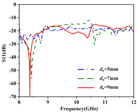
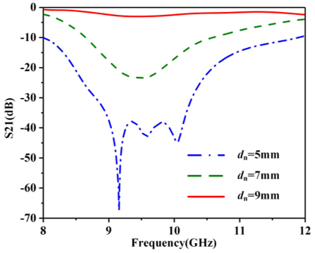
Figure 3: Simulated S parameters of the antenna with different d values: (a) and ( b) .
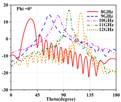
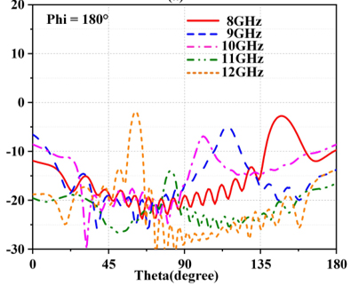
Figure 4: Radiation pattern of LWA with d 5 mm in (a) phi 0 and (b) phi 180.
The relative distance between the centerline of the circular patches and the SSPP line determines the coupling strength, which can be adjusted by modifying the parameter d. Figure 3 shows the simulated S parameters of the antenna at different coupling distances d at 10 GHz. Within the entire operating frequency band, the reflection coefficient is less than -10 dB, and the transmission coefficient of d 5 mm is less than -10 dB from 8 to 12 GHz. As d increases, the value of significantly increases, indicating more energy being transmitted to the end of the antenna due to weaker coupling strength.
The SSPP-fed circular patch array antenna has a wide bandwidth and stable radiation pattern without increasing the antenna area. Figure 4 shows the radiation pattern of the SSPP antenna when the coupling distance dis 5 mm. It can be seen that the proposed SSPP antenna achieves a scanning range of 36 to 118 (phi 0) in the bandwidth from 8 to 12 GHz. The radiation gain is above 12 dBi. From the simulation results, the designed SSPP antenna has a high SLL throughout the operating frequency band, with a maximum SLL of -9 dB. For example, the reason for the decrease in gain at 10 GHz is that a uniform aperture field distribution results in a wider half-power beamwidth (HPBW) and high SLL. Next, we will adjust the coupling distance d of different radiation patches to achieve tapered aperture field distribution to implement low SLL.
B. Design of low SLL
For low SLL designs, it is necessary to adjust the aperture field distribution on the antenna surface. The attenuation constant corresponding to the aperture field distribution can be calculated to determine the coupling distance. Aperture field distribution E(z) and the attenuation constant distribution (z) has the following relationship [19]:
| (2) |
where R represents the ratio of power absorbed by the terminal load, while l is the distance from the antenna’s origin to the point under concern. R can be calculated by:
| (3) |
In equation (2), the value of R varies with the aperture field distribution, which can be set to the average of the values obtained under different coupling distances. For the specific antenna structure, where l 320 mm and d varies from 5 to 11 mm, R is set to the average value of 0.5.
According to [16, 20], when the aperture field distribution E(z) of a leaky wave antenna follows the cosine distribution along the z-direction, the antenna will have a low SLL. Consequently, the same distribution is applied to the aperture field here, which can be expressed as [16]:
| (4) |
Substituting equation (4) into equation (2) can obtain the distribution of the attenuation constant over the antenna length under the cosine aperture field distribution, as shown in Figs. 5 (a) and (b).
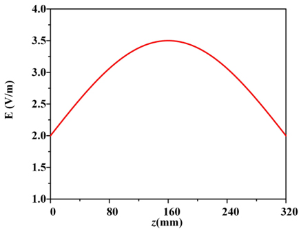
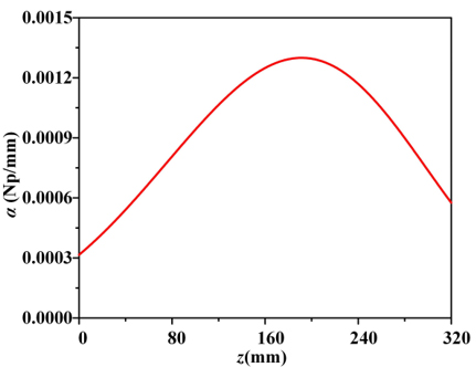
Figure 5: Distribution of (a) and (b) .
For a uniform traveling wave structure, the attenuation constant can be calculated from S parameters of the structure by the formula:
| (5) |
The unit in the equation is dB/mm. To obtain represented by Np per unit length, the expression 1 Np 8.686 dB is used. Figure 3 (b) gives the transmission coefficients corresponding to different coupling distances d. By combining equation (5), we can obtain the relationship between coupling distance and attenuation constant, as shown in Fig. 6 (a). Therefore, combining equations (2) and (5) can indirectly obtain the relationship between aperture field E(z) and coupling distance d, as shown in Fig. 6 (b). This helps to design the desired aperture field distribution.
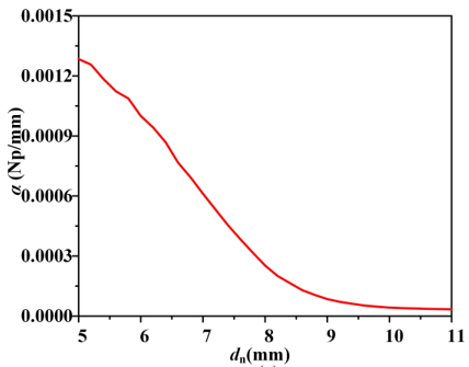
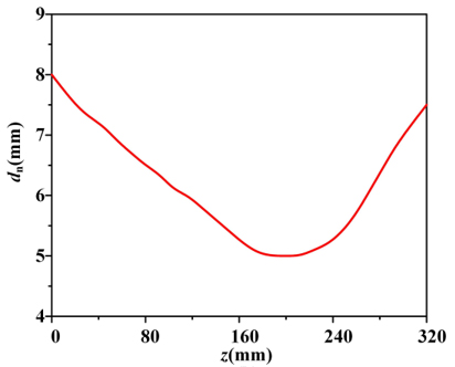
Figure 6: (a) Variations of attenuation constant as functions of d and (b) variation of d along z-axis.
Table 1: The optimized values of 24 patches’ coupling distance (unit: mm)
| Parameter | Value | Parameter | Value |
| d | 11.5 | d | 5.52 |
| d | 10.98 | d | 5 |
| d | 10.59 | d | 5 |
| d | 9.94 | d | 5 |
| d | 9.42 | d | 5 |
| d | 8.9 | d | 5 |
| d | 8.51 | d | 5.52 |
| d | 7.86 | d | 6.56 |
| d | 7.6 | d | 7.6 |
| d | 7.08 | d | 8.12 |
| d | 6.56 | d | 8.64 |
| d | 6.04 | d | 9.16 |
According to the generated curve of Fig. 6 (b), the positions of radiation patches have been rearranged. The patches at various positions were optimized in EM simulation software, to implement as low SLL as possible throughout the entire X-band (from 8 to 12 GHz). The coupling distance between the patch array and the SSPP line has been optimized according to appropriate proportional multiples. Table 1 shows the final optimized coupling distance.
Figures 7 (a) and (b) show the top view of the SSPP antenna with uniform d 5 mm (Antenna A) and the SSPP antenna with optimized d (Antenna B). Figures 7 (c) and (d) illustrate the far-field radiation patterns following the implementation of the low SLL design. It can be seen that compared with Antenna A, the first sidelobe at 10 GHz of Antenna B is decreased from -11.8 to -29.4 dB and the first sidelobe at 12 GHz is decreased from -12.2 to -24.3 dB. The results indicate that this method is feasible. However, we can observe the antenna’s back-lobe level remains significantly higher than -15 dB at low frequencies, specifically at 8 GHz. Hence, we need to further implement low back-lobe level.
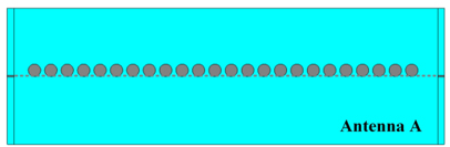
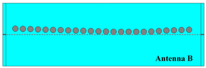
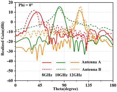
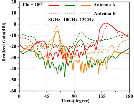
Figure 7: (a) Antenna A with uniform d 5 mm, (b) antenna B with optimized d, (c) radiation pattern of the two antennas in phi 0 at 8, 10, 12 GHz, and (d) radiation pattern of the two antennas in phi 180 at 8, 10, 12 GHz.
C. Design of low back-lobe level
From Fig. 7 (c), we can see that the back-lobe level at 8 GHz is still high due to the existence of surface waves, dispersing the energy radiated along the main direction and increasing the SLL of the SSPP antenna. EBG is a stopband structure used to reduce the energy coupling between antennas [21]. Mushroom-shaped EBG is the most commonly used structure [22]. They are often used in antennas to prevent the propagation of surface waves, achieve a gain enhancement, and reduce the SLL of antennas. Therefore, a mushroom-shaped EBG structure is introduced to suppress surface waves, as shown in Figs. 8 (a) and (b). The EBG metasurface is composed of a metal ground, a dielectric substrate (F4B), a square patch, and metal via holes inside the dielectric substrate. The unit of the metal patch is connected to the grounding plate on the other side of the dielectric substrate through the metal via hole.
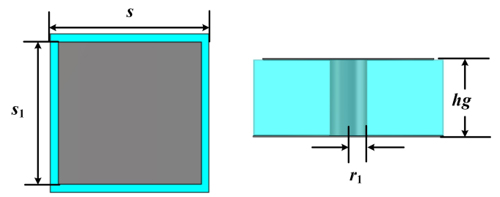
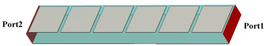
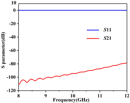
Figure 8: (a) Top view of the EBG unit, (b) side view of the EBG unit, (c) 3-D view of the proposed EBG structure, and (d) S parameters of the proposed EBG structure (s 4.5 mm, s 5 mm, r 0.5 mm, hg 2 mm).
This structure can exhibit high impedance performance within the operating frequency band, suppressing surface waves on the substrate of the antenna. By using the waveguide transmission method shown in Fig. 8 (c), the simulated results in Fig. 8 (d) show its stopband effect reaches -80 dB in the X-band.
Figures 9 (a) and (b) illustrate the geometry of the designed antenna. The simulated results of the far-field radiation pattern at 8 GHz is shown in Figs. 9 (c) and (d). It can be seen that the back-lobe level of the antenna with EBG has decreased from -10.8 to -16.8 dB, which indicates that the back-lobe level reduction can be achieved by loading EBG structures on both sides of theantenna.
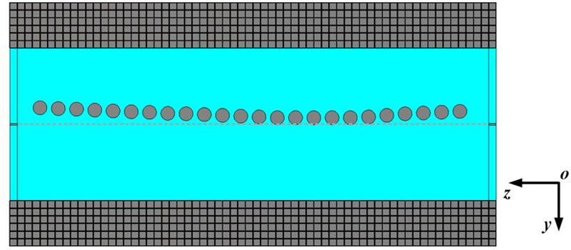
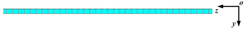
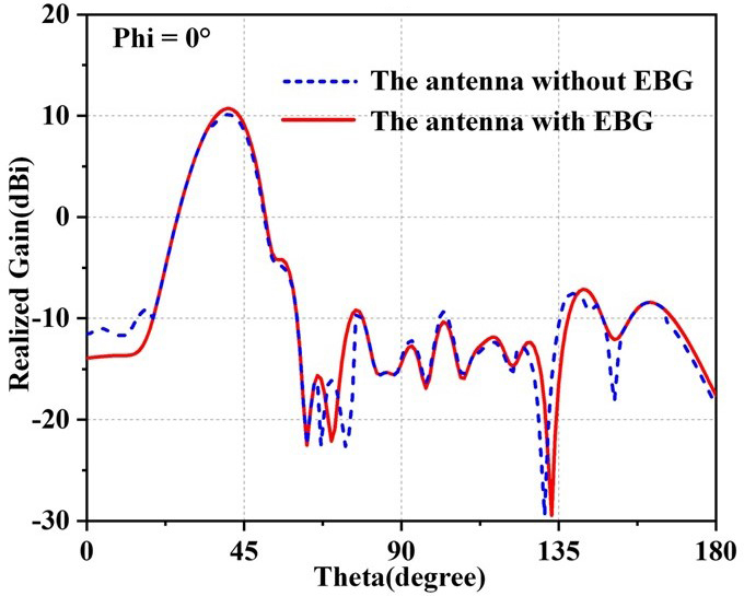
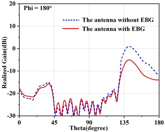
Figure 9: (a) Top view of the antenna with EBG, (b) side view of the antenna with EBG, (c) radiation pattern of the antenna in phi 0 at 8 GHz, and (d) radiation pattern of the antenna in phi 180 at 8 GHz.
The simulation results of the LWA antenna with low SLL design are shown in Fig. 10. From Fig. 10 (a), it can be seen that the operating frequency band still covers the X-band. The simulated radiation efficiency of LWAs without low SLL design and with low SLL design is shown in Fig. 10 (b). The maximum radiation efficiency of LWAs without low SLL design and with low SLL design is 95.8% and 92.4%, respectively. The proposed LWA with low SLL design has a radiation efficiency of approximately 83.6% in the working band. Simulated radiation patterns are shown in Figs. 10 (c) and (d), which shows that the antenna has a scanning angle range of 32 to 114 (phi 0) from 8 to 12 GHz, and the highest SLL in the entire frequency band is less than -15 dB. The optimal SLL can reach approximately -23 dB at 10 GHz.
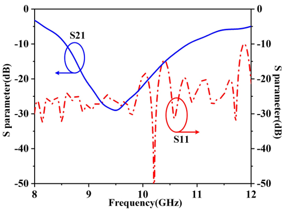
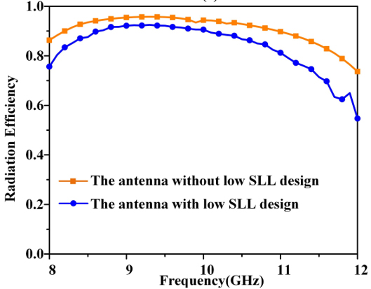
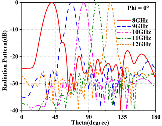
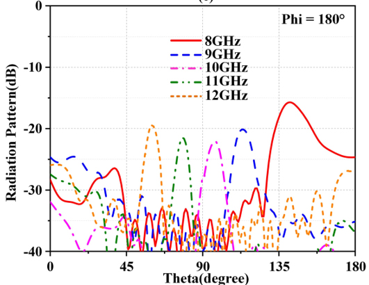
Figure 10: (a) Simulated S parameters of the proposed LWA, (b) simulated radiation efficiency of the LWA, (c) simulated radiation patterns of the LWA in phi 0, and (d) simulated radiation patterns of the LWA in phi 180.
III. MEASURED RESULTS AND DISCUSSION
We manufactured and measured the proposed SSPP-fed circular patch array antenna. The photograph of the SSPP antenna is presented in Fig. 11. The two layers of the antenna are aligned and secured by nylon columns, while the EBG structure and antenna are fastened together with metal sheets and additional nylon columns on the back side of the assembly. The port on the right side of the antenna is connected to a 50 matched load. The simulated and measured reflection and transmission coefficients are shown in Fig. 11. It shows that the measured results agree well with the simulated results. The measured S is below -10 dB, covering the required operating frequency band of 8 to 12 GHz.
Minor deviations may be mainly caused by SMA soldering and antenna warping. In CST simulation, the SMA soldering is induced by creating slots near the input and output ports and introducing parasitic capacitance (0.4 pF) in these slots. As shown in Fig. 11 (c), the simulated result considering the SMA soldering is closer to the measured result. Since the antenna is large and its ends are a bit warped, a higher air layer is introduced. The antenna warping is simulated by adding a 0.16 mm air layer between the two dielectric substrates in the CST model. As shown in Fig. 11 (d), the resonance frequency of S considering the antenna warping is shifted to a higher frequency, which agrees better with the measured results.
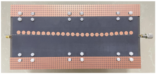
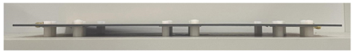
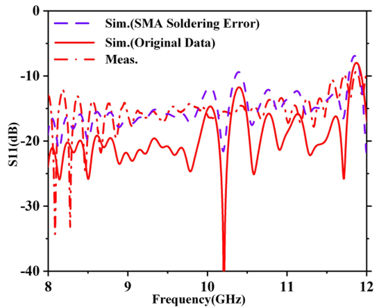
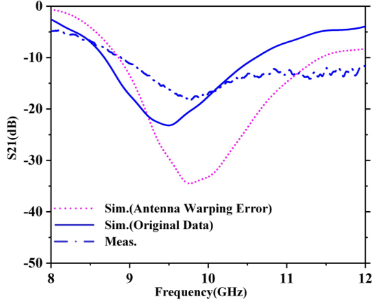
Figure 11: Fabricated prototype and the simulated and measured S parameters of the proposed LWA: (a) top view, (b) side view, (c) simulated and measured S, and (d) simulated and measured S.
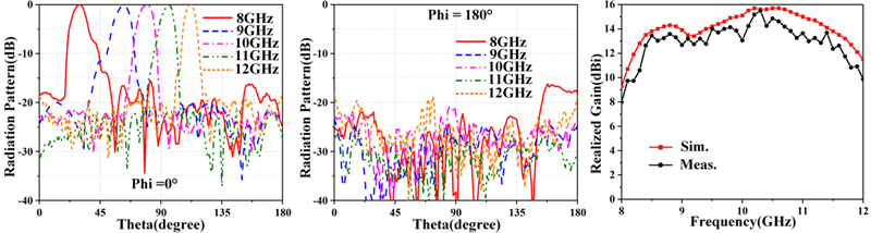
Figure 12: (a) Measured radiation patterns of the LWA in phi , (b) measured radiation patterns of the LWA in phi 180, and (c) comparison between the measured and simulated realized gain.
Table 2: Comparison of the proposed SSPP antenna with other referenced prototypes
| Ref. | Antenna Type | Bandwidth | Scanning Range | SLL (dB) |
| [7] | SSPP | 8.79.9 GHz (12.9%) | 133.7153.9 (20.2) | -7 |
| [8] | SSPP-fed circular patch array | 511 GHz (75%) | 57112 (55) | -7 |
| [9] | SSPP-fed elliptical patch array | 9.812.28 GHz (22.5%) | 2169 (167) | -5 |
| [10] | SSPP-fed circular patch array | 1115 GHz (30.8%) | 58124 (66) | -10 |
| [11] | SSPP-fed elliptical patch array | 1215 GHz (22.2%) | 76128 (52) | -20 |
| [13] | Slot array | 9.810.2 GHz (0.04%) | 118122 (4) | -20 |
| [14] | Slot array | 29.129.4 GHz (0.01%) | 65.168 (2.9) | -17 |
| [15] | SIW slot | 8.511 GHz (25.6%) | 79110 (31) | -20 |
| [17] | SIW slot | 3337 GHz (11.4%) | 44.362.9 (18.6) | -20 |
| Proposed | SSPP-fed circular patch array | 812 GHz (40%) | 30112 (82) | -15 |
The measured radiation pattern of the antenna is shown in Figs. 12 (a) and (b). It indicates that the antenna has a wide scanning range from 30 to 112 (phi 0) in the operating band from 8 to 12 GHz, and the maximum SLL in the whole frequency band is lower than -15 dB. The realized gain of the LWA in the beam direction is shown in Fig. 12 (b), which is from 8 to 15.7 dBi. At both ends of the operating band, the lower antenna gain is due to the narrower bandwidth of S.
Table 2 compares the proposed SSPP-fed circular patch array antenna with other referenced prototypes. In [8–10], the scanning range is efficiently extended using SSPP-fed patch array antennas, but the SLL rises as the scanning angle increases. In [9], despite a scanning range of 167 achieved, the SLL increases to -5 dB. SLL below -15 dB was attained in [13, 14, 15, 17], however, the scanning range was constrained and failed to extend beyond 32. Although it successfully lowers the SLL of the SSPP antenna in [11], the scanning range is only 52, which is limited for radar applications. In summary, the proposed SSPP-fed circular patch array increases the scanning angle range by adopting a double-layer coupled SSPPs feeding structure to increase the antenna impedance bandwidth, which can cover a wide scanning range from 30 to 112 (phi 0) in the X-band and have a maximum SLL below -15 dB, making it suitable for radar detection.
IV. CONCLUSION
This paper proposes a frequency beam scanning antenna with broadband, wide-angle, and low SLL characteristics, adopting an SSPP-fed circular patch array method to achieve broadband and wide-angle scanning range. The tapered attenuation constant distribution is accomplished by changing the coupling strength between the patch elements and the SSPP line, while dielectric surface wave suppression is achieved by adopting EBG structures, resulting in extremely low SLL over the entire frequency band. The experimental results indicate that the antenna has wide-angle scanning ability and low SLL characteristics. In the operating frequency range of 8 to 12 GHz, the scanning angle measured by the antenna is 82 and a maximum SLL less than -15 dB. This antenna has potential application prospects in the field of low-altitude, slow-speed, and miniaturized target detection radar due to its low manufacturing cost, wide-angle scanning range in broadband, and low SLL.
ACKNOWLEDGMENT
This work was supported in part by National Natural Science Foundation of China (61971469), and Fundamental Research Funds of Shaanxi Key Laboratory of Artificially-Structured Functional Materials and Devices (AFMD-KFJJ-21105).
REFERENCES
[1] A. A. Oliner and A. Hessel, “Guided waves on sinusoidally-modulated reactance surfaces,” IRE Trans. Antennas Propag, vol. 7, no. 5, pp. 201-208, 1959.
[2] J. L. Gomez-Tornero, F. D. Quesada-Pereira, and A. Alvarez-Melcon, “Analysis and design of periodic leaky-wave antennas for the millimeter waveband in hybrid waveguide-planar technology,” IEEE Trans. Antennas Propag, vol. 53, no. 9, pp. 2834-2842, 2005.
[3] J. B. Pendry, L. Martín-Moreno, and F. J. Garcia-Vidal, “Mimicking surface plasmons with structured surfaces,” Science, vol. 305, no. 5685, pp. 847-848, 2004.
[4] X. Shen, T. J. Cui, D. Martin-Cano, and F. J. Garcia-Vidal, “Conformal surface plasmons propagating on ultrathin and flexible films,” Proc. Natl. Acad. Sci., vol. 110, no. 1, pp. 40-45, 2013.
[5] D. Zhang, X. Liu, Y. Sun, K. Zhang, Q. Wu, Y. Li, and T. Jiang. “Compact transition enabled broadband propagation of spoof surface plasmon polaritons based on the equivalent circuit model,” J. Phys. D: Appl. Phys., vol. 55, no. 16, p. 165101, 2022.
[6] D. Zhang, X. Liu, Y. Sun, K. Zhang, Q. Wu, Y. Li, T. Jiang, and S. N. Burokur, “Dispersion engineering of spoof plasmonic metamaterials via interdigital capacitance structures,” Opt. Lett., vol. 48, pp. 1383-1386, 2023.
[7] G. S. Kong, B. G. Cai, H. F. Ma, and T. J. Cui, ”Continuous leaky-wave scanning using periodically modulated spoof plasmonic waveguide,” Sci. Rep., vol. 6, no. 29600, pp. 1-9, 2016.
[8] J. Y. Yin, J. Ren, and Q. Zhang, “Frequency-controlled broad-angle beam scanning of patch array fed by spoof surface plasmon polaritons,” IEEE Trans. Antennas Propag., vol. 64, no. 12, pp. 5181-5189, 2016.
[9] L. Jidi, X. Cao, J. Gao, T. Li, H. Yang, and S. Li, “Ultrawide-angle and high-scanning-rate leaky wave antenna based on spoof surface plasmon polaritons,” IEEE Trans. Antennas Propag., vol. 70, no. 3, pp. 2312-2317, 2022.
[10] D. F. Guan, P. You, Q. Zhang, Z. H. Lu, S. W. Yong, and K. Xiao, “A wide-angle and circularly polarized beam-scanning antenna based on microstrip spoof surface plasmon polariton transmission line,” IEEE Antennas Wirel. Propag. Lett., vol. 16, pp. 2538-2541, 2017.
[11] H. W. Yu, Y. C. Jiao, and Z. Weng, “Spoof surface plasmon polariton-fed circularly polarized leaky-wave antenna with suppressed side-lobe levels,” Int. J. RF Microw. Comput. Aided Eng., vol. 30, no. 3, pp. 1-9, 2020.
[12] A. Mallahzadeh and S. Mohammad-Ali-Nezhad, “Periodic collinear-slotted leaky wave antenna with open stopband elimination,” IEEE Trans. Antennas Propag., vol. 63, no. 12, pp. 5512-5521, 2015.
[13] M. T. Mu and Y. J. Cheng, “Low-sidelobe-level short leaky-wave antenna based on single-layer PCB-based substrate-integrated image guide,” IEEE Antennas Wirel. Propag. Lett., vol. 17, no. 8, pp. 1519-1523, 2018.
[14] P. F. Kou and Y. J. Cheng, “Ka-Band low-sidelobe-level slot array leaky-wave antenna based on substrate integrated nonradiative dielectric waveguide,” IEEE Antennas Wirel. Propag. Lett., vol. 16, pp. 3075-3078, 2017.
[15] N. Javanbakht, M. S. Majedi, and A. R. Attari, “Thinned array inspired quasi-uniform leaky-wave antenna with low side-lobe level,” IEEE Antennas Wirel. Propag. Lett., vol. 16, pp. 2992-2995, 2017.
[16] J. Guo, Z. Li, J. Wang, M. Chen, and Z. Zhang, “Analysis and design of leaky-wave antenna with low SLL based on half-mode SIW structure,” Int. J. Antennas Propag., vol. 2015, pp. 1-5, 2015.
[17] Y. J. Cheng, W. Hong, K. Wu, and Y. Fan, “Millimeter-wave substrate integrated waveguide long slot leaky-wave antennas and two-dimensional multibeam applications,” IEEE Trans. Antennas Propag., vol. 59, no. 1, pp. 40-47, 2011.
[18] X. Huo, J. Wang, Z. Li, Y. Li, M. Chen, and Z. Zhang, “Periodic leaky-wave antenna with circular polarization and low-SLL properties,” IEEE Antennas Wirel. Propag. Lett., vol. 17, no. 7, pp. 1195-1198, 2018.
[19] A. A. Oliner and D. R. Jackson, “Leaky-wave antennas,” in Antenna Engineering Handbook, 4th ed. J. L. Volakis, Ed. New York, NY: McGraw-Hill, 2007.
[20] F. L. Whetten and C. A. Balanis, “Meandering long slot leaky-wave waveguide-antennas,” IEEE Trans. Antennas Propag., vol. 39, no. 11, pp. 1553-1560, 1991.
[21] F. Yang and Y. Rahmat-Samii, “Microstrip antennas integrated with electromagnetic bandgap (EBG) structure: A low, mutual coupling design for array applications,” IEEE Trans. Antennas Propag., vol. 51, no. 10, pp. 2936-2946, 2003.
[22] A. H. Panaretos and D. H. Werner, “A note on the isolation performance of nonuniform capacitively loaded mushroom-type EBG surfaces within a parallel plate waveguide,” IEEE Trans. Antennas Propag., vol. 63, no. 11, pp. 5175-5180, 2015.
BIOGRAPHIES

Yanzhen Shi received the B.S. degree in communication engineering from Shanghai Normal University, Shanghai, China, in 2021. She is currently pursuing the master’s degree in communication and information system at Shanghai University. Her research interests include beaming scanning antenna, direction of arrival estimation and radar detection.

Zhibo Fan received the B.S. degree in communication engineering from Shanghai University of Electric Power, Shanghai, China, in 2020. She is currently pursuing the master’s degree in communication and information system at Shanghai University. Her research interests include frequency scanning antennas and metamaterials.

Cong Chen received a Ph.D. degree in radio physics from Wuhan University, Wuhan, Hubei, China, in 2009. From 2009 to 2021, he worked in Wuhan Maritime Communication Research Institute, Wuhan, Hubei, China. Currently, he is a Research Fellow with Electronic Information School, Wuhan University, Wuhan, Hubei, China. His research interests include phased array antenna, beaming scanning antenna, and radar scattering.

Yongjin Zhou received the B.S. degree in communication engineering from Shandong University, Jinan, China, in 2006, and Ph.D. degree in electromagnetic field and microwave technology from Southeast University, Nanjing, China, in 2011, respectively. From 2009 to 2010, he was a visiting scholar of University of Houston. From 2011 to 2012, he was a software engineer with EEBU of Marvell Technology (Shanghai) Ltd. From 2012 to 2015, he was an Assistant Professor, and from 2015 to 2020, he was an Associate Professor with School of Communication & Information Engineering, Shanghai University, Shanghai, China. Currently, he is a Professor with School of Communication & Information Engineering, Shanghai University, Shanghai, China. He has authored and coauthored over 90 papers in peer-reviewed journals and conference proceedings. He is IEEE Member, OSA Member, and Senior Member of Chinese Institute of Electronics. He is serving as a Reviewer for over 20 peer-reviewed journals, such as Nature Electronics, Photonic Research, Optics Letter, Optics Express, Appl. Phys. Express, IEEE Access, IEEE MTT, and IEEE MWCL. He has served as a Session Chair for several International Symposiums. His current research interests include microwave and millimeter antenna, plasmonic metamaterials and applications, millimeter wave and THz functional devices and wireless energy transmission.
ACES JOURNAL, Vol. 39, No. 10, 916–926
doi: 10.13052/2024.ACES.J.391010
© 2024 River Publishers