Higher-order Method of Moments Analysis of Waveguide with Irregular Cross-sections
Ning Ding, Zhongchao Lin, Lei Yin, Xunwang Zhao, and Yu Zhang
1School of Electronic Engineering
Xidian University, Xi’an 71000, China
2Shaanxi Key Laboratory of Large-Scale Electromagnetic Computing
Xi’an 71000, China
nding@stu.xidian.edu.cn, zclin@xidian.edu.cn, yyparrot@126.com, xdzxw@126.com, yuseexidian@163.com
Submitted On: May 29, 2023; Accepted On: October 15, 2024
ABSTRACT
Antennas fed by waveguides with irregular cross-sections are efficiently simulated through the hybridization of the mode-matching (MM) method and the higher-order method of moments (HOMoM). To obtain the waveguide modes required in the MM method, a 2-D finite element method (FEM) is utilized and combined with the hybrid MM/HOMoM method, which enables the proposed method to model irregular waveports. The accuracy and efficiency of the proposed method are demonstrated by simulating log-periodic antennas (LPAs) and an asymmetric single-ridge slot waveguide antenna.
Index Terms: Eigenvalues, finite element method (FEM), higher-order method of moments (HOMoM), irregular cross-sections, mode-matching (MM), waveports.
I. INTRODUCTION
Waveguides are widely used in antennas due to their high power capabilities and low loss properties. With the development of microwave technology, the structures of microwave devices and waveport aperture surfaces tend to become increasingly complicated. Therefore, the accurate and efficient simulation of microwave devices with waveports has attracted much attention.
For the analysis of waveguide problems, the method of moments (MoM) is widely considered numerically accurate [1]. On the other hand, due to the high efficiency of the mode-matching (MM) method, it has been widely used to design waveguide components. As a result, the MoM and MM method are hybridized to analyze waveguide coupling and radiation problems [2]. In 2000, the MM/MoM hybrid method was applied to analyze the metallic N-port waveguide structures, where the RWG basis functions were used for modeling, and the electric field integral equation (EFIE) was adopted for construction of the impedance matrix [3]. The Piggio-Miller-Chang-Harrington-Wu-Tsai (PMCHWT) formulation was utilized for analyzing dielectric loaded waveguides [4]. Later, the higher-order vector basis functions modeled with curvilinear triangles were used to improve the simulation efficiency of non-rotationally symmetric structures [5]. In 2015, the MM method was introduced to the higher-order method of moments (HOMoM) for constructing perfectly matching terminators for waveports. The higher-order basis functions modeled with quadrilaterals further reduced the number of unknowns [6]. Recently, a set of coupled integral formulations were derived to handle the loading problem of the metal-dielectric composite structures, and the orders of the basis functions were adaptively adjusted, yielding accurate and effectiveresults [7].
However, the majority of previous investigations focused on regular waveguides, such as rectangular and circular ones. The previous method is no longer applicable when the cross-section of the waveport becomes irregular due to fabrication or architectural requirements, e.g. the coaxial center conductor may be eccentric or non-cylindrical [8]. Therefore, modeling of waveguides with irregular cross-sections based on the hybrid MM/MoM method is worth discussing.
In this paper, the MM/HOMoM method and FEM are hybridized to solve the coupling and radiation problems fed by waveports with irregular cross-sections. The use of higher-order basis function defined on the bilinear quadrilaterals can greatly improve efficiency while maintaining numerical accuracy, and the adoption of FEM extends the flexibility.
II. THEORY AND FORMULATION
A. MM/HOMoM hybrid method
Let us consider an arbitrarily shaped cavity containing several objects connected by N waveports, as depicted in Fig. 1. The object surfaces are classified into three categories: metallic, dielectric, and composite metal-dielectric surfaces [9].
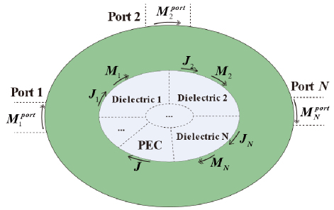
Figure 1: Multiport cavity structure containing composite objects connected by N waveports.
The unknown current densities are expanded by a set of linearly independent basis functions and as:
| (1) |
where denotes the wave impedance of free space, and , , and represent the number of unknowns in the scattering body and waveguide apertures, respectively. , , and represent the unknown coefficients. is the higher-order basis functions defined on the quadrilaterals, and the definition is given in [10]. denotes the waveguide basis functions defined on the apertures of waveguides, which is expanded using the eigenvectors of different waveport modes.
Since the analysis of conventional scattering problems has been discussed in detail previously [9, 11], this paper discusses only the matrix associated with the waveguide basis functions. According to the equivalence principle, the surface integral equation of the electromagnetic field could be established. The integral equations can be written as follows by applying boundary conditions to the waveguide apertures, the metallic surfaces, and the dielectric surfaces, respectively:
| (2) |
where the real number equals 1.0 when modeling the dielectric surfaces or waveguide apertures and 0 otherwise. The integral operators and are the same as [6]. and denote the electric and magnetic currents defined on the i-th surface of the elements, which are discretized with the higher-order basis functions defined on bilinear quadrilateral elements, and (i 1,2,3 …) is the unit normal vector on the i-th surface.
Adopting the MM technique, the electromagnetic field outside the waveport can be written as [6]:
The whole structure is divided into the scattering body (represented by s) and waveports (denoted by p). Using Galerkin’s method to test the above equation with the basis functions of the scatterer body and the basis functions of the waveports, the integral equations of matrix form can be written as:
| (4) |
where is the unknown coefficients vector associated with the scattering body, and is the unknown coefficients vector associated with the waveport aperture. represents the right-hand vector excited by the waveport. represents the impedance matrix resulting from the interaction of structures a and b. Letters a and b can be replaced by s (the scattering body) or p (the waveport).
The matrix elements in (4) can be expressed as:
| (5) | ||||
| (6) | ||||
| (7) | ||||
| (8) |
where m and n denote the row and column numbers of the matrix elements, denotes inner product operator, and the definition of is the same as in (2).
B. Analysis of waveguide eigenvalue problem
A variety of methods are used to analyze the waveguide cross-sectional field distribution, including MoM, FDTD, and FEM. Among all these methods, 2-D FEM is the most generally applicable and versatile [12].
Here, to facilitate integrated modeling, the 2-D vector FEM is adopted to analyze the waveguide eigenvalue problems. The tangential electric field and longitudinal electric field on the element are defined as follows, where and W represent the scalar and vector basis functions, respectively [13, 14]:
| (9) | |||
| (10) | |||
| (11) |
where (i 1,2,3) are area coordinates of the element, is length of edge that starts from node i to node j, is the gradient operator, and and represent the coefficients to be solved for the transverse and direction vectors, respectively.
In order to obtain the eigenvector of the waveguide aperture, the generalized eigenmatrix equation is derived from the Helmholtz equation [12]:
| (12) | |||
| (13) | |||
| (14) | |||
| (15) | |||
| (16) |
where and represent relative permeability and permittivity of the medium corresponding with the waveguide, is the propagation constant, is the wave number of free space, is the cross-section of the waveguide apertures, and and W represent the scalar and vector basis functions [10, 11].
According to (18), the orthonormal modal field distributions on quadrilaterals are obtained through the operation, is the i-th mode normalized eigenvector of the waveguide, is the excitation mode, and is Kronecker delta:
| (17) |
Finally, by using nested one-dimensional Gaussian sampling on the quadrilaterals, we obtain the modal field distribution at the Gaussian sampling points of the waveguide aperture. Applying the results to matrix elements, the 2-D FEM is associated with the MM/HOMoM hybrid method, making the method more flexible.
III. NUMERICAL EXAMPLE
Simulation examples are given in this section to validate the accuracy and computational efficiency of the proposed method, and all simulations employ double-precision numerical accuracy. The computational platform used in these examples is a workstation with two Intel Xeon(R) Gold 5118 CPUs and 512 GB RAM.
A. Asymmetrical single-ridged slotted waveguide antenna
Due to the advantages of easy fabrication and low loss, slotted waveguide antennas have been widely used. Among these, the asymmetrical slotted waveguide antenna is not only small in size, but also has good low sidelobe characteristics [15, 16]. Firstly, a slotted antenna fed by an asymmetrical single-ridged waveguide is analyzed to demonstrate the flexibility of the proposed method. As shown in Fig. 2 and Table 1, the dimensions of the waveport aperture and antenna model are given here, and all slots are the same size. The other side of the antenna waveguide port is connected to a matched terminator.
The S11 is computed from 8.5 to 9.5 GHz (11 frequency points). The model is discretized into 7774 quadrilateral elements and expanded into 15418 unknowns using the proposed method. When using triangles for modeling in FEKO, the antenna is discretized into 17187 meshes and 26949 RWG-MoM unknowns when using a mesh size.
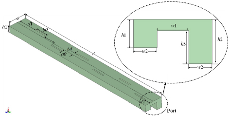
Figure 2: 3-D model of the slotted waveguide antenna and dimensions of the single-ridged waveport cross-section.
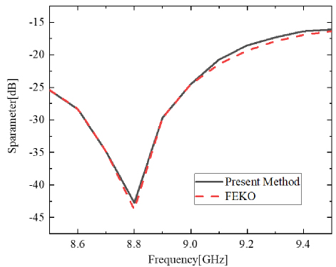
Figure 3: Comparison of S parameters of the slotted waveguide antenna.
Table 1: Geometrical parameters of the slotted waveguide antenna. All dimensions are in millimeters (mm)
| w | w1 | w2 | l | d1 | d2 |
| 13.72 | 5.48 | 4.12 | 131.9 | 15.7 | 4.55 |
| a0 | b0 | h1 | h2 | h3 | |
| 0.9 | 10.15 | 4.93 | 7.76 | 5.79 | 4.41 |
Table 2: Computational statistics of the slotted waveguide antenna when 24 cores are used
| Method | Present Method | FEKO() |
| Number of Unknowns | 15418 | 26949 |
| Memory [GB] | 3.5 | 10.8 |
| Time [s] | 1071 | 4554 |
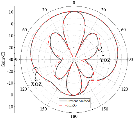
Figure 4: Radiation pattern of the single-ridged waveguide antenna.
The S parameter and computational statistics comparison are depicted in Fig. 3 and Table 2. The proposed method’s efficiency is much greater than the RWG-MoM in FEKO. Moreover, the radiation pattern of the slotted antenna is computed. The operating frequency is set to 8.8 GHz, which is the resonant frequency of the waveguide. As seen in the Fig. 4, the gain of the xoz plane and the yoz plane agree well.
B. Log-periodic antennas
A log-periodic antenna (LPA) is then analyzed to illustrate the accuracy and efficiency of the proposed method. The 3-D model of the antenna is shown in Fig. 5, and the dimensions of the antenna are listed in Table 3. The antenna consists of two orthogonal linear polarization elements and a perfect electric conductor (PEC) reflector plane. The antenna has the following parameters: number of elements N 18, scaling factor 0.77, and spacing factor 0.125. The lengths (l), widths (w), and spacings (r) of the antenna decrease logarithmically as defined by the geometric ratio and the spacing factor [17, 18]. The top two identical waveguide ports are arranged orthogonally asfeeders:
| (18) | ||||
| (19) |
The operating frequency of the simulation is carried out in 1.0 GHz, and the model is discretized into 6140 bilinear quadrilaterals and 12290 unknowns when using the proposed method. The model was discretized into 13926 triangular patches in FEKO, and the mesh size was , yielding 20869 RWG-MoM unknowns. For comparison, the result of FEM is also given to verify the correctness of the proposed method, in which the residual is set to 0.005.
Figure 6 shows a comparison of the radiation pattern results. It can be observed that the presented method in this paper has great agreement with FEKO and FEM within the main lobe, with a small difference below -20 dB. The computational statistics are summarized in Table 4. Due to the use of higher-order basis functions, the number of unknowns can be effectively reduced in the proposed method compared to the RWG-MoM without losing numerical accuracy. Furthermore, the proposed method has advantages in memory and solution time.
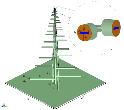
Figure 5: 3-D model of the log-periodic antenna.
Table 3: Geometrical parameters of the log-periodic antenna. All dimensions are in millimeters (mm)
| a | b | c | d | e |
| 2.5 | 0.5 | 3.6 | 1000.0 | 18.0 |
| l | h | w | r | d |
| 350.0 | 17.0 | 16.8 | 178.0 | 66.0 |
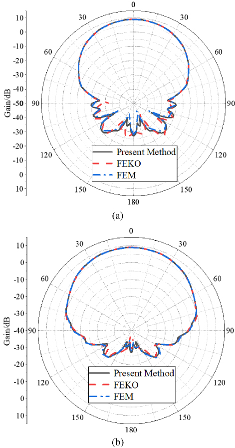
Figure 6: Radiation patterns of the log-periodic antenna:(a) xoz plane (b) yoz plane.
Table 4: Computational statistics of the log-periodic antenna when eight cores are used
| Method | Present Method | FEKO() |
| Number of Unknowns | 12290 | 20869 |
| Memory [GB] | 2.3 | 6.5 |
| Time [s] | 119 | 437 |
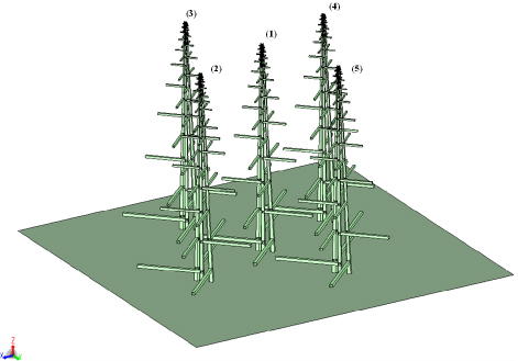
Figure 7: 3-D model of the log-periodic antenna array.
Table 5: Distribution of the log-periodic antenna in the xoy plane. All dimensions are in millimeters (mm)
| Index | Coordinates |
| (1) | |
| (2) | |
| (3) | |
| (4) | |
| (5) |
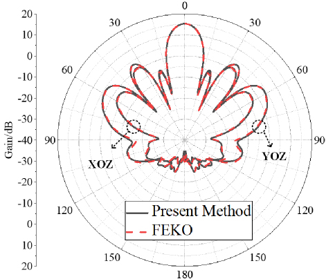
Figure 8: Radiation pattern of the log-periodic antenna array.
Table 6: Computational statistics of the log-periodic antenna array when 24 cores are used
| Method | Present Method | FEKO() |
| Number of Unknowns | 58332 | 102799 |
| Memory [GB] | 50.7 | 157.5 |
| Time [s] | 1619 | 14025 |
To further illustrate the effectiveness of the current approach, we present an example of an LPA array. This array consists of the five antenna elements mentioned above and a PEC reflector with a side length of 2000 mm. Figure 7 and Table 5 show the 3-D model of the array and the distribution in the xoy plane. Figure 8 gives the comparison of the radiation pattern between the present method and FEKO. Additionally, as indicated in Table 6, the proposed method outperforms RWG-MoM in terms of memory usage and time required.
IV. CONCLUSION
The MM/HOMoM method and FEM are hybridized to analyze waveguide problems with irregular cross-sections. In order to facilitate integrated modeling, 2-D FEM is used to solve the eigenvalue problem of the waveguide. In addition, higher-order basis functions are used to reduce the unknowns effectively. Results show that the proposed method has the advantage of high efficiency and high numerical accuracy.
ACKNOWLEDGMENT
This work was supported by the Key Research and Development Program of Shaanxi (2022ZDLGY02-03, 2023-ZDLGY-42, 2021GXLH-02) and the Fundamental Research Funds for the Central Universities (QTZX23018).
REFERENCES
[1] A. J. Sangster and H. Wang, “A combined FEM/MOM technique of coupling and radiating apertures in rectangular waveguide,” IEEE Trans. Magn., vol. 31, no. 3, pp. 1554-1557, May 1995.
[2] F. Arndt, “Fast CAD and optimization of waveguide components and aperture antennas by hybrid MM/FE/MoM/FD methods-state-of-the-art and recent advances,” IEEE Trans. Microw. Theory Techn., vol. 52, no. 1, pp. 292-305, Jan. 2004.
[3] R. Bunger and F. Arndt, “Moment-method analysis of arbitrary 3-D metallic N-port waveguide structures,” IEEE Trans. Microw. Theory Techn., vol. 48, no. 4, pp. 531-537, Apr. 2000.
[4] V. Catina, F. Arndt, and J. Brandt, “Hybrid surface integral-equation/mode-matching method for the analysis of dielectric loaded waveguide filters of arbitrary shape,” IEEE Trans. Microw. Theory Techn., vol. 53, no. 11, pp. 3562-3567, Nov. 2005.
[5] V. Catina and F. Arndt, “Fast method-of-moments analysis of a class of dielectric loaded horns applying higher-order vector basis functions,” in IEEE AP-S Int. Antennas Propag. Symp., Honolulu, HI, pp. 3596-3599, 2007.
[6] Y. Wang, X. Zhao, Y. Zhang, S. W. Ting, T. K. Sarkar, and C. H. Liang, “Higher order MoM analysis of traveling-wave waveguide antennas with matched waveports,” IEEE Trans. Antennas Propag., vol. 63, no. 8, pp. 3718-3721, Aug. 2015.
[7] Z. Lin, X. Zhao, Y. Zhang, and H. Liu, “Higher order method of moments analysis of metallic waveguides loaded with composite metallic and dielectric structures,” IEEE Trans. Antennas Propag., vol. 66, no. 9, pp. 4958-4963, Sep. 2018.
[8] M. Razmhosseini, R. Zabihi, and R. G. Vaughan, “Wideband antennas using coaxial waveguide,” IEEE Trans. Antennas Propag., vol. 69, no. 10, pp. 6273-6283, Oct. 2021.
[9] K. C. Donepudi, J.-M. Jin, and W. C. Chew, “A higher order multilevel fast multipole algorithm for scattering from mixed conducting/dielectric bodies,” IEEE Trans. Antennas Propag., vol. 51, no. 10, pp. 2814-2821, Oct.2003.
[10] B. M. Kolundzija, “Electromagnetic modeling of composite metallic and dielectric structures,” IEEE Trans. Micro. Theory Techn., vol. 47, no. 7, pp. 1021-1032, July 1999.
[11] P. Yla-Oijala and M. Taskinen, “Application of combined field Integral equation for electromagnetic scattering by dielectric and composite objects,” IEEE Trans. Antennas Propag., vol. 53, no. 3, pp. 1168-1173, Mar. 2005.
[12] J. F. Lee, D.K. Sun, and Z. J. Cendes, “Full-wave analysis of dielectric waveguides using tangential vector finite elements,” IEEE Trans. Microw. Theory Techn., vol. 39, no. 8, pp. 1262-1271, Aug. 1991.
[13] R. D. Graglia, P. Petrini, and A. F. Peterson, “Full-wave analysis of inhomogeneous waveguiding structures containing corners with singular hierarchical curl-conforming vector bases,” IEEE Antennas Wireless Propag. Lett., vol. 13, pp. 1701-1704, 2014.
[14] K. Zhang, C.-F. Wang, and J.-M. Jin, “Broadband monostatic RCS and ISAR computation of large and deep open cavities,” IEEE Trans. Antennas Propag., vol. 66, no. 8, pp. 4180-4193, Aug. 2018.
[15] W. Wang, S. S. Zhong, Y.-M. Zhang, and X.-L. Liang, “A broadband slotted ridge waveguide antenna array,” IEEE Trans. Antennas Propag., vol. 54, no. 8, pp. 2416-2420, Aug. 2006.
[16] V. V. Zemlyakov, G. F. Zargano, A. A. Gadzieva, and S. V. Krutiev, “Microwave slot antenna based on asymmetrical ridged waveguide,” Int. Conf. Antenna Theory Techn., pp. 193-195, Sep. 2013.
[17] O. Sushko, S. Piltyay, and F. Dubrovka, “Symmetrically fed 1–10 GHz log-periodic dipole antenna array feed for reflector antennas,” in 2020 IEEE Ukrainian Microw. Week (UkrMW), Kharkiv, Ukraine, pp. 222-225, 2020.
[18] H. Qi, “Elimination of anomalous resonances in coaxial-fed LPDA and its array with integrated -shaped balun,” IEEE Trans. Antennas Propag., vol. 71, no. 11, pp. 9000-9005, Nov. 2023.
BIOGRAPHIES

Ning Ding received the B.S. degree from Xidian University, Xi’an, China, in 2017, and is currently working toward the Ph.D. degree at Xidian University. His current research interest is computational electromagnetics.

Zhongchao Lin received the B.S. and Ph.D. degrees from Xidian University, Xi’an, China, in 2011 and 2016, respectively. In 2016, he joined Xidian University as a Post-Doctoral Fellow, where he was lately promoted as an Associate Professor. His research interests include large-scale computational electromagnetics, scattering, and radiation electromagnetic analysis.

Lei Yin was born in Yinchuan,Ningxia, China, in 1995. He received the B.S. degree in electronic and information engineering from Xidian University, Xi’an, China, in 2017. He is currently pursuing the Ph.D. degree with Xidian University, Xi’an, China. His current research interests include computational electromagnetic, parallel computing, and electromagnetic radiation and coupling.

Xunwang Zhao received the B.S. and Ph.D. degrees from Xidian University, Xi’an, China, in 2004 and 2008, respectively. He joined Xidian University in 2008 as a Faculty Member, where he was lately promoted as a Full Professor. He was a Visiting Scholar with Syracuse University, Syracuse, NY, USA, from December 2008 to April 2009. As a Principal Investigator, he works on several projects, including the project of NSFC. His research interests include computational electromagnetics and electromagnetic scattering analysis.

Yu Zhang received the B.S., M.S., and Ph.D. degrees from Xidian University, Xi’an, China, in 1999, 2002, and 2004, respectively. In 2004, he joined Xidian University as a Faculty Member. He was a Visiting Scholar and an Adjunct Professor with Syracuse University, Syracuse, NY, USA, from 2006 to 2009. As a Principal Investigator, he works on projects, including the project of NSFC. He has authored four books, Parallel Computation in Electromagnetics (Xidian University Press, 2006), Parallel Solution of Integral Equation-Based EM Problems in the Frequency Domain (Wiley IEEE, 2009), Time and Frequency Domain Solutions of EM Problems Using Integral Equations and a Hybrid Methodology (Wiley, 2010), and Higher Order Basis Based Integral Equation Solver (Wiley, 2012), as well as more than 100 journal articles and 40 conference papers.
ACES JOURNAL, Vol. 40, No. 2, 89–95
doi: 10.13052/2025.ACES.J.400201
© 2025 River Publishers