Simulation Analysis of Electromagnetic Environment Effect and Shielding Effectiveness for VPX Chassis under Plane Wave Radiation
Hongkun Ni, Hong Jiang, Xinbo Li, Qian Jia, and Xiaohui Wang
1College of Communication Engineering
Jilin University, Changchun, 130012 China
jiangh@jlu.edu.cn
*Corresponding Author
2Research and Development Department
China Academy of Launch Vehicle Technology, Beijing 100076, China
Submitted On: May 24, 2023; Accepted On: November 27, 2023
ABSTRACT
The chassis based on the VPX bus standard structure has been widely applied to the fields of vehicle, missile, radar, etc. In this paper, we analyze the electromagnetic environment effect on VPX chassis via the CST software, and investigate the electromagnetic coupling characteristics of VPX chassis under 20 v/m plane wave radiation according to the RS103 test defined in the MIL-STD-461G standard. By simulation, we analyze the electromagnetic coupling paths of the VPX chassis, find the key positions of the electromagnetic protection such as the air intake, air outlet, trapdoor, and panel gaps, and we propose the electromagnetic protective measures for the weak parts of the VPX chassis. The electromagnetic shielding effectiveness before and after protection design is evaluated. Finally, the simulation results are verified by the experiments. It has guiding significance for the electromagnetic protection design of VPX chassis.
Keywords: VPX chassis, shielding effectiveness, electromagnetic environment effect, electromagnetic protection.
I. INTRODUCTION
In recent years, aerospace electronic technology is developing rapidly, and its applications are becoming increasingly extensive. With the emergence of various types of electronic devices, the requirements for their performance and response speed in aerospace and other fields are becoming higher [1-4]. With the rapid development of electronic equipment with different functions, the structure and performance of the traditional chassis cannot meet the load-bearing requirements of the new generation of electronic equipment [5, 6]. VPX is a new generation high-speed serial bus standard Versa Module European (VME) proposed by the International Trade Association (VITA) [7]. The VPX chassis based on VITA46 standard is a new type of chassis, which has strong shock resistance and impact resistance through reinforcement technology [8, 9]. Its internal space design is compact, and the position and routing planning of each module are clear, so that it has the smallest volume as far as possible under the premise of ensuring the normal work of each piece of equipment, which is convenient for installation, maintenance, handling, and replacement. At present, the chassis and electronic equipment based on VPX bus standard structure have been successfully applied to the fields of vehicle, missile, aircraft, radar, etc. [10-14]. The stability and environmental adaptability of the VPX chassis under plane wave radiation need to be further verified. It is a prerequisite and a necessary requirement to analyze the electromagnetic environmental effects of the VPX chassis and propose protective measures in order for the chassis and its internal electronic equipment to work normally in complex electromagnetic environments [15-20]. However, in the existing literature, the electromagnetic environment effect of the VPX chassis has not been well investigated, whether with theoretical calculation or simulation methods. In addition, the existing electromagnetic protection design for VPX chassis was completed via experimental measurements, which has greatly increased the cost of the electromagnetic protection design.
In this paper, considering that the shape of the VPX chassis is irregular, the electromagnetic environment effect of the VPX chassis is analyzed via the Computer Simulation Technology (CST) software [21], which is based on the transmission line method (TLM). The electromagnetic coupling characteristics of VPX chassis under 20 v/m plane wave radiation is investigated according to the RS103 test defined in the MIL-STD-461G standard [22]. The electric field energy density distribution and surface current distribution of the VPX chassis at different frequencies are obtained by CST simulations. The electromagnetic coupling paths of the VPX chassis are analyzed, the key positions of the electromagnetic protection of the VPX chassis such as the air intake, air outlet, trapdoor, and panel gaps are determined, and the protective measures for the weak parts are proposed. The electromagnetic shielding effectiveness before and after protection design is evaluated, and the simulation results are verified by the experiments.
II. PERFORMANCE METRICS OF ELECTROMAGNETIC COUPLING CHARACTERISTICS
A. Energy density of electric field intensity
The energy density of an electric field is the energy of the electric field per unit volume, which is expressed as
| (1) |
where E is the electric field intensity and is a half of the permittivity.
In the CST electromagnetic simulation software, the electric field energy density monitor can be set to monitor the electric field energy density at different frequency points under plane wave radiation. The larger the electric field energy density is, the greater the amount of electromagnetic coupling is. Therefore, the electric field energy density can be used as an important performance metric to analyze the electromagnetic coupling path of a shielding enclosure [23-26].
B. Shielding effectiveness
Generally, shielding effectiveness is used to evaluate the shielding performance of a shield body, denoted as
| (2) |
refers to the electric field intensity at the position of interest inside the shield body under the radiation of plane wave, and refers to the electric field intensity at the location of interest without the shield body under plane wave radiation.
III. SIMULATION SETTINGS
According to the standard of RS103 electric field radiation sensitivity in MIL-STD-461G, the CST electromagnetic simulation software is used to numerically model and analog the test conditions. According to the simulation requirements, basic settings are first carried out in the CST studio suite, including the operating frequency band selection, and excitation source settings.
A. VPX chassis model
The units of physical quantities are set as dimensions (mm), frequency (GHz), temperature (Kelvin), and time (ns). We set the chassis material as PEC (ideal conductor), the background material as normal, and the boundary condition as open. A typical VPX chassis model 1:1 is imported into CST microwave studio. The VPX chassis model is shown in Fig. 1.
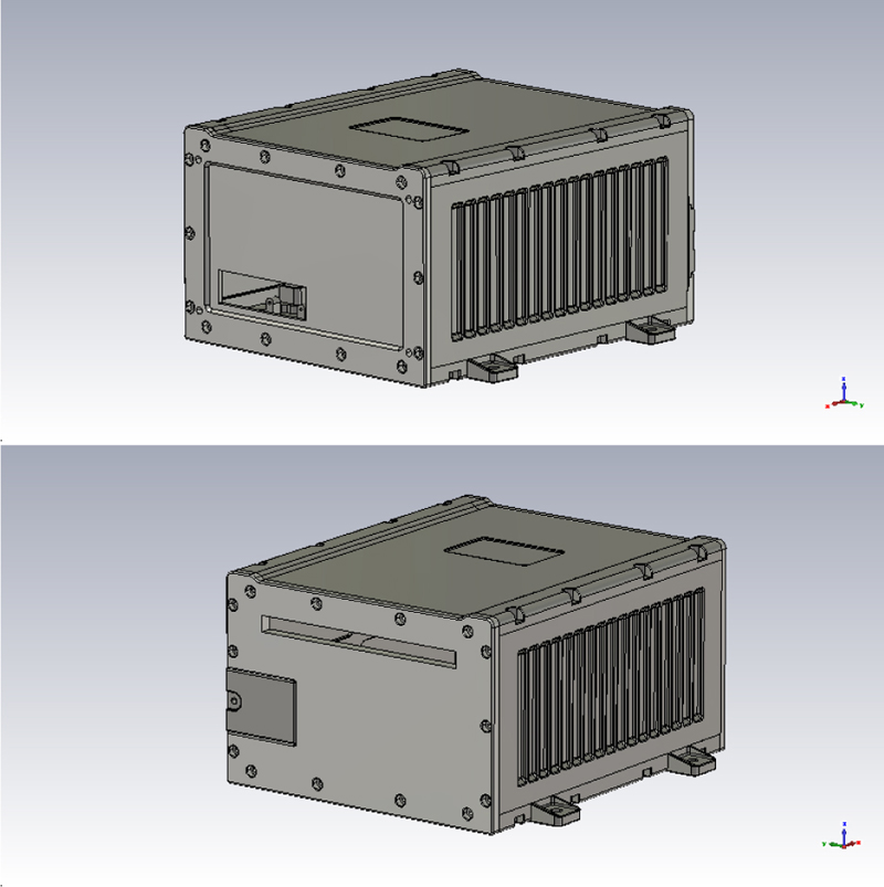
Figure 1: The VPX chassis model.
Table 1: Applicable frequency range
| No. | Frequency Range | Applications |
|---|---|---|
| 1 | 10 kHz-2 MHz | Army aircraft applicable, other options |
| 2 | 2 MHz-30 MHz | For army ships, army aircraft and navy, the others shall be selected by the purchaser |
| 3 | 30 MHz-100 MHz | All applicable |
| 4 | 100 MHz-1 GHz | All applicable |
| 5 | 1 GHz-18 GHz | All applicable |
| 6 | 18 GHz-40 GHz | Selected by the purchaser |
B. Frequency range and excitation signal
In the experiment of RS103 electric field radiation sensitivity in MIL-STD-461G, the frequency range and corresponding applications are given in Table 1.
We analyze the electromagnetic environment effect and shielding effectiveness of the VPX chassis via the CST simulation. Assume a plane wave with a frequency domain value of 20 v/m to radiate the VPX chassis. The type of excitation signal is impulse, whose approximate expression is
| (3) |
where is the amplitude coefficient, is the frequency domain value, and are the maximum and minimum angular frequencies, respectively, and is the time offset. The excitation signal in time and frequency domains is shown in Fig. 2.
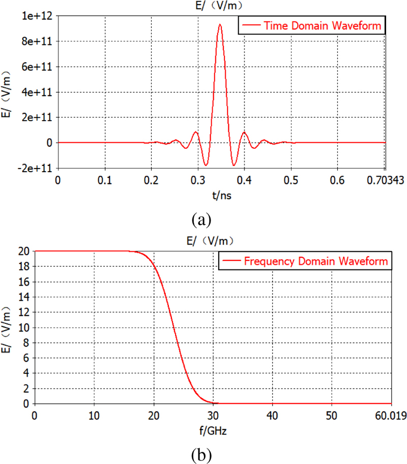
Figure 2: Excitation signal: (a) Time domain and (b) frequency domain.
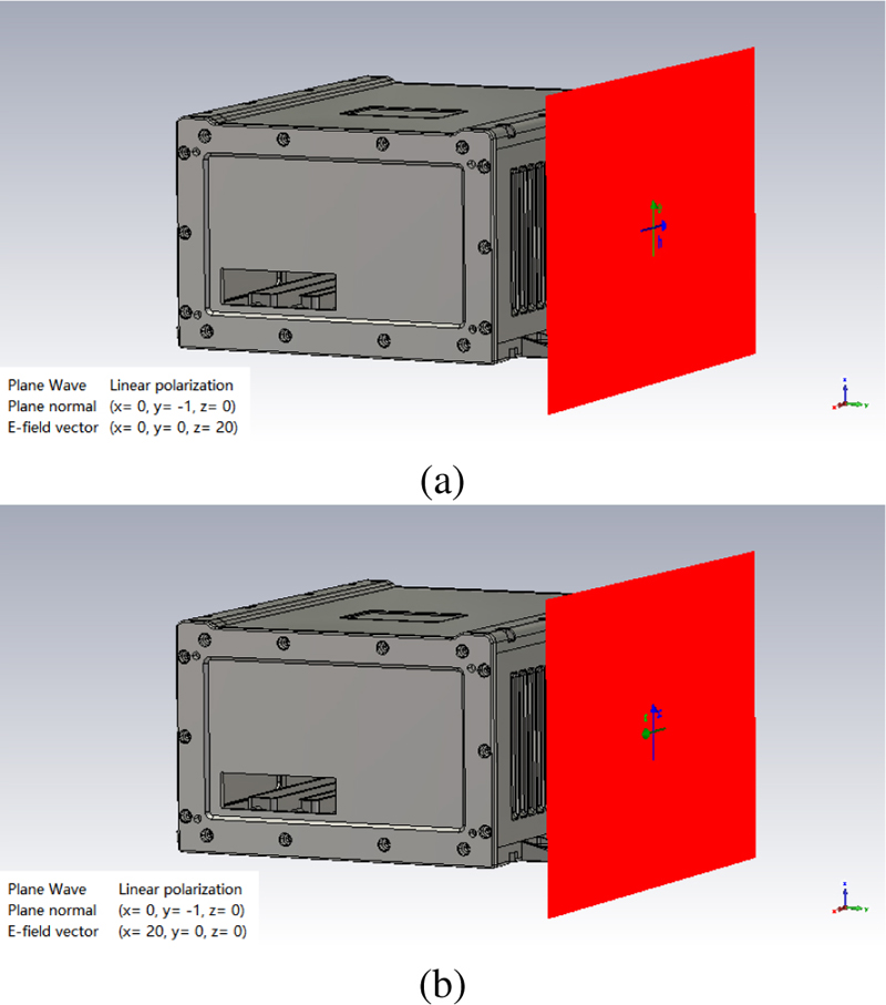
Figure 3: Polarization modes of excitation source: (a) Vertical polarization and (b) horizontal polarization.
In the CST simulation, the external high-frequency electromagnetic environment is simulated. Assume that the excitation source is linear polarization mode. The vertical and horizontal polarizations are respectively set to examine the coupling characteristics of the chassis for different polarization modes, as shown in Fig. 3.
C. Electric field probes
From the preliminary analysis of the chassis structure, it is found that the key positions of the chassis vulnerable to electromagnetic interference are the air intake, air outlet, trapdoor, and panel gaps. Thus, the electric field probes are set at these three key positions to monitor the electric field intensity, as shown in Fig. 4.
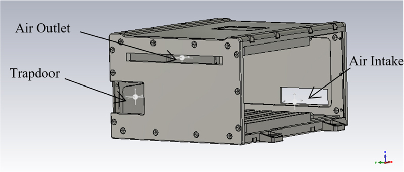
Figure 4: Electric field probes.
IV. ELECTROMAGNETIC COUPLING PATH ANALYSIS OF VPX CHASSIS
The electric field intensity monitor and electric field energy density monitor at different frequency points are set with the CST simulation software, and the frequency points are selected as 1 GHz, 3 GHz, 5 GHz, 7 GHz, 9 GHz, 11 GHz, 13 GHz, 15 GHz, 17 GHz, 18 GHz under plane wave radiation. The electric field energy density distribution and surface current distribution of the air intake, air outlet, trapdoor, and panel gaps of the VPX chassis are obtained, as shown in Figs. 5-10, from which we can analyze the electromagnetic coupling paths of the VPX chassis.
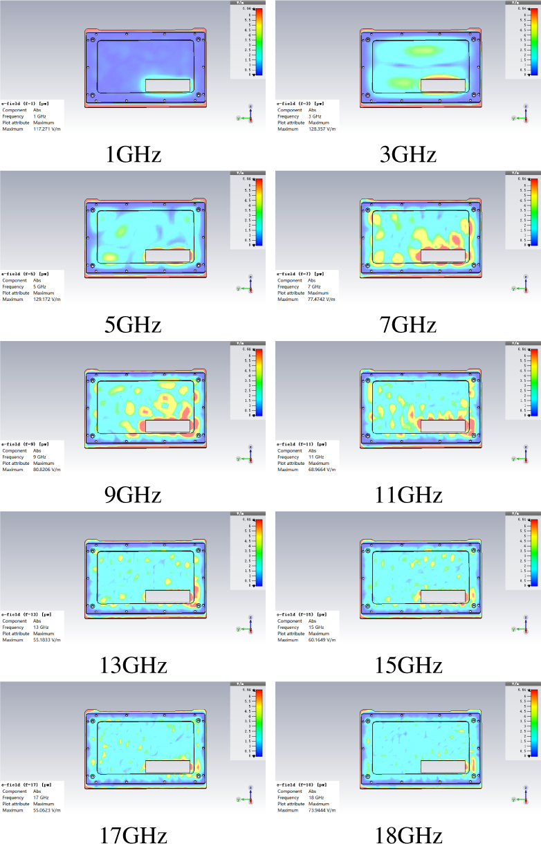
Figure 5: Electric field energy distribution of the air intake.
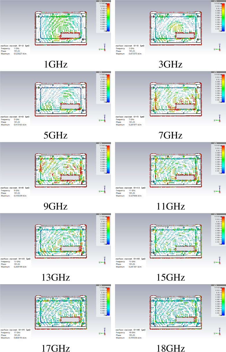
Figure 6: Surface current distribution of the air intake.
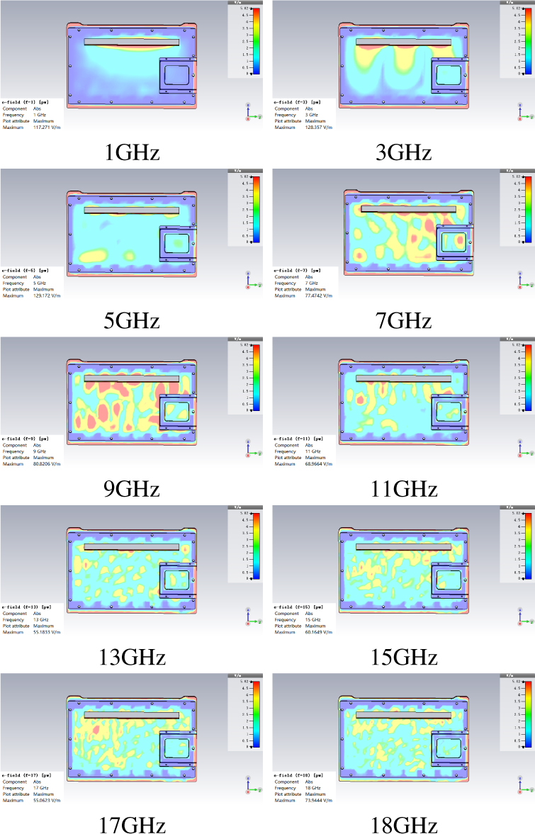
Figure 7: Electric field energy distribution of the air outlet and trapdoor.
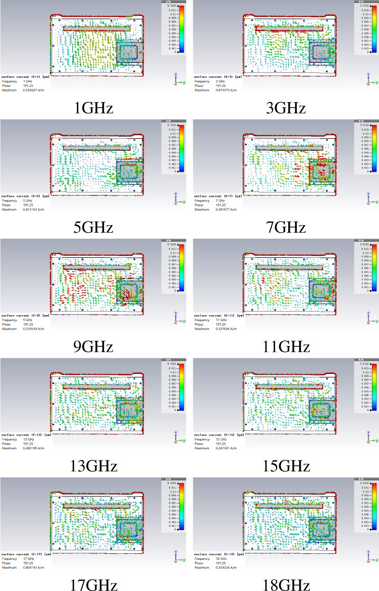
Figure 8: Surface current distribution of the air outlet and trapdoor.
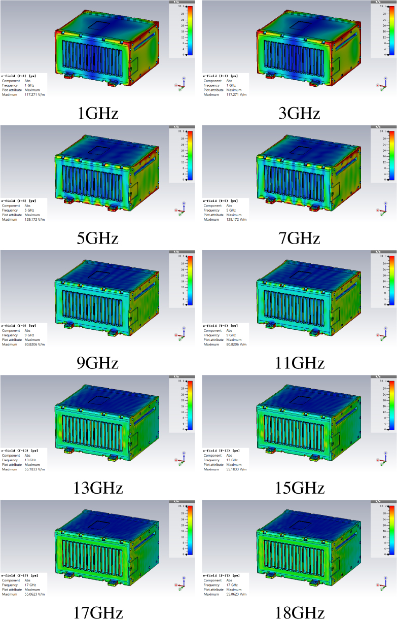
Figure 9: Electric field energy distribution of the panel gaps.
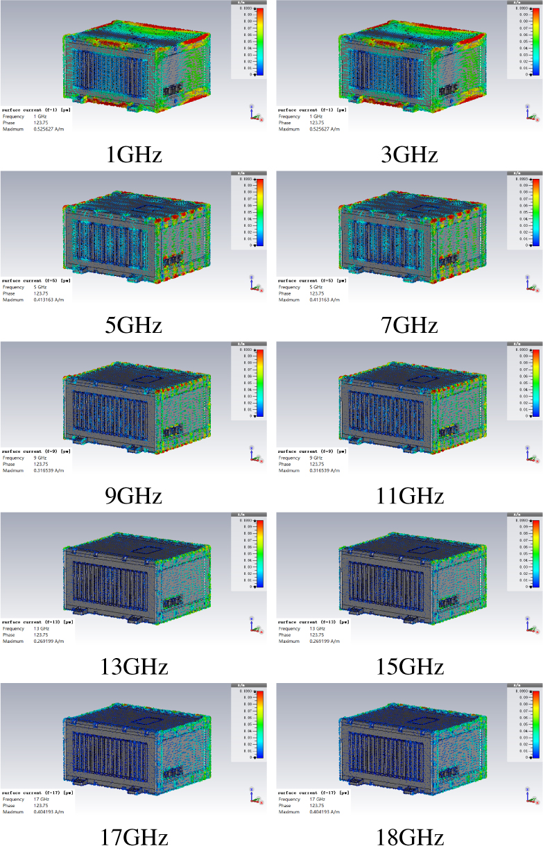
Figure 10: Surface current distribution of the panel gaps.
It can be seen from Figs. 5-10 that, the electromagnetic coupling paths of the front panel of the VPX chassis come from the air intake and the panel gap. The maximum coupling values of the air intake appear at 7 GHz, 9 GHz, and 11 GHz, and the panel gap at 1 GHz, 3 GHz, and 5 GHz. The electromagnetic coupling paths of the back panel of the VPX chassis come from the air outlet, trapdoor, and panel gap. The maximum coupling values of the air outlet and trapdoor appear at 7 GHz, 9 GHz, and 11 GHz, and the panel gap at 1 GHz, 3 GHz, and 5 GHz. The VPX fan chassis needs to dissipate heat through the air intake and air outlet, where there is a large amount of electromagnetic coupling and a great impact on the electromagnetic shielding performance of the VPX chassis.
V. PROTECTION DESIGN OF AIR INTAKE, AIR OUTLET, AND TRAPDOOR
Electric field intensities are calculated via simulation by setting electric field probes in the key positions of the VPX chassis, then the shielding effectiveness before and after protection design is evaluated.
A. Electric field intensity of the air intake, air outlet, and trapdoor
For the key positions such as the air intake, air outlet, and trapdoor, the electric field intensity in the horizontal and vertical polarization modes in the frequency domain are calculated. The simulation result of the air intake, the air outlet, and the trapdoor are shown in Figs. 11, 12, and 13, respectively.
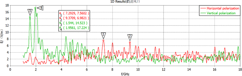
Figure 11: Electric field intensity of the air intake.
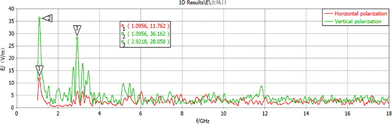
Figure 12: Electric field intensity of the air outlet.
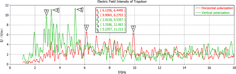
Figure 13: Electric field intensity of the trapdoor.
It can be seen that the electric field intensity of vertical polarization is higher than that of horizontal polarization in the above three key positions. For the air intake, the maximum coupling value of 17.224 v/m is obtained at 1.9561 GHz for vertical polarization, and 7.5602 v/m is obtained at 7.2929 GHz for horizontal polarization. For the air outlet, the maximum coupling is 36.162 v/m at 1.0956 GHz for vertical polarization and 11.762 v/m for horizontal polarization. For the trapdoor, the maximum coupling volume is 11.213 v/m at 5.2357 GHz for vertical polarization, and 6.4445 v/m at 6.1296 GHz for horizontal polarization.
B. Shielding effectiveness of the air intake, air outlet, and trapdoor
According to (2), we respectively calculate the shielding effectiveness of the intake, outlet, and trapdoor before protection design. The calculation results of the air intake, air outlet and trapdoor are shown in Figs. 14-16.
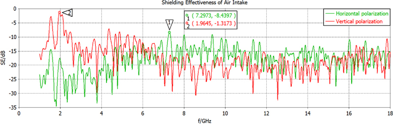
Figure 14: Shielding effectiveness of the air intake.
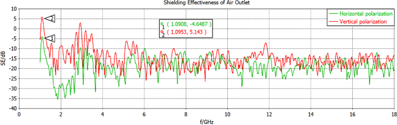
Figure 15: Shielding effectiveness of the air outlet.
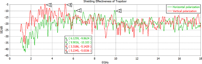
Figure 16: Shielding effectiveness of the trapdoor.
It can be seen from Figs. 14-16 that the shielding effectiveness of the fan-type VPX chassis is greatly affected by the coupling between the air intake and the air outlet, so it is of great significance to design the protection of the air intake and the air outlet.
C. Evaluation of shielding effectiveness after protection design
To protect the VPX chassis, we install the metal shielding nets at the air intake and air outlet, as shown in Fig. 17.
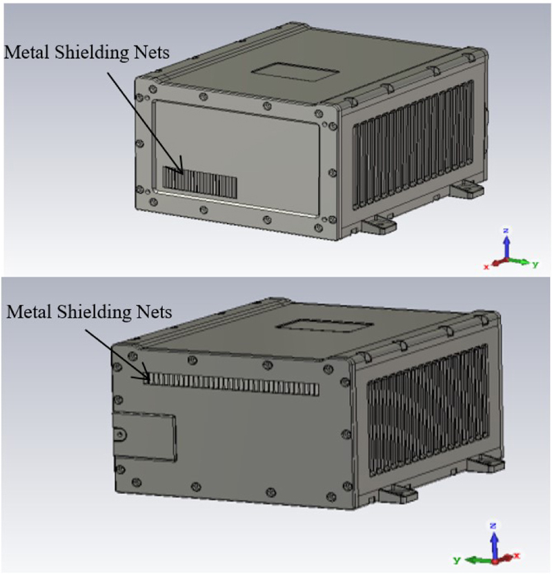
Figure 17: Installation of metal shielding nets at the air intake and the air outlet.
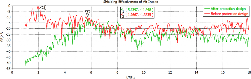
Figure 18: Shielding effectiveness of the air intake after protection design.
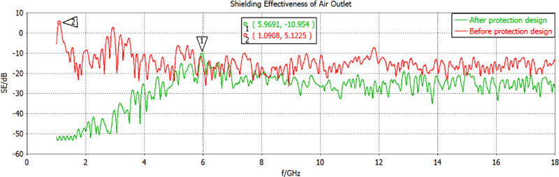
Figure 19: Shielding effectiveness of the air outlet after protection design.
Through the simulation analysis of the VPX chassis after installing the metal shielding nets, the electric field intensities at the air intake and the air outlet can be obtained. Despite that there is no protection design at the trapdoor, its electric field intensity has also reduced. Vertical polarization as an example, according to (2), the shielding effectiveness of the intake, outlet, and trapdoor after protection design is respectively calculated. The results of the above three key positions are shown in Figs. 18, 19, and 20, respectively.
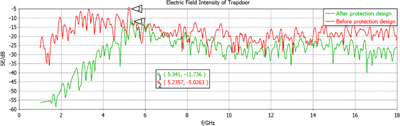
Figure 20: Shielding effectiveness of the trapdoor after protection design.
Compared with the results before protection design, it is revealed that through the protection design, the VPX chassis can obtain higher shielding effectiveness in the three key positions. It increases to 11.348 dB at the air intake, 10.954 dB at the air outlet, and 11.736 dB at the trapdoor.
VI. PROTECTION DESIGN OF PANEL GAPS
Besides the intake, outlet and trapdoor, the protection design of the panel gaps is also important for the VPX chassis. In this case, we use absorbing sticky paper to cover the panel gaps to reduce the electromagnetic leakage. Assume that the probe is set in the geometric center of the VPX chassis, as shown in Fig. 21, and the placement of the absorbing sticky paper as shown in Fig. 22. Vertical polarization as an example, the electric field intensity, and shielding effectiveness of the VPX chassis before and after protection design are simulated, and the results are shown in Figs. 23 and 24, respectively.
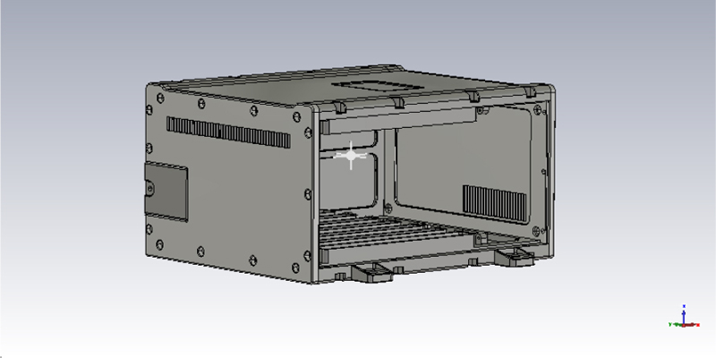
Figure 21: The probe position inside the VPX chassis.
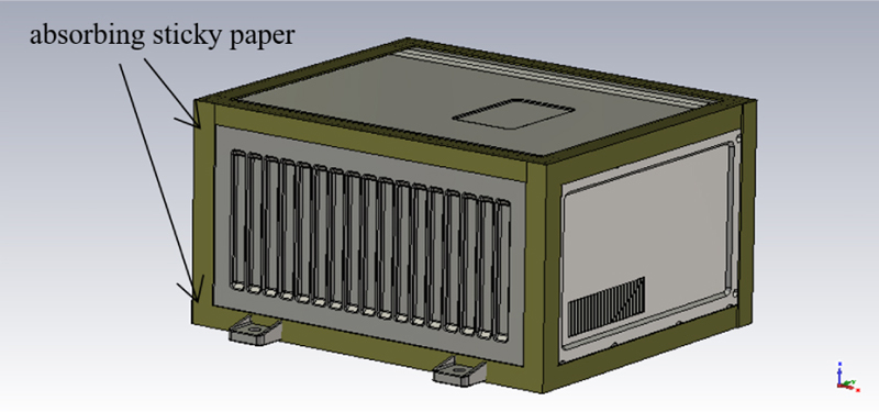
Figure 22: Protection of panel gaps with absorbing sticky paper.
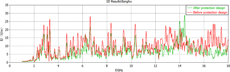
Figure 23: Electric field intensity at the probe position.
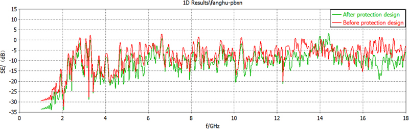
Figure 24: Shielding effectiveness at the probe position.
As seen in Figs. 23 and 24, by the protection design of panel gaps, the electric field intensity after protection design has much reduced, and the shielding effectiveness has greatly increased compared with that before protection design.
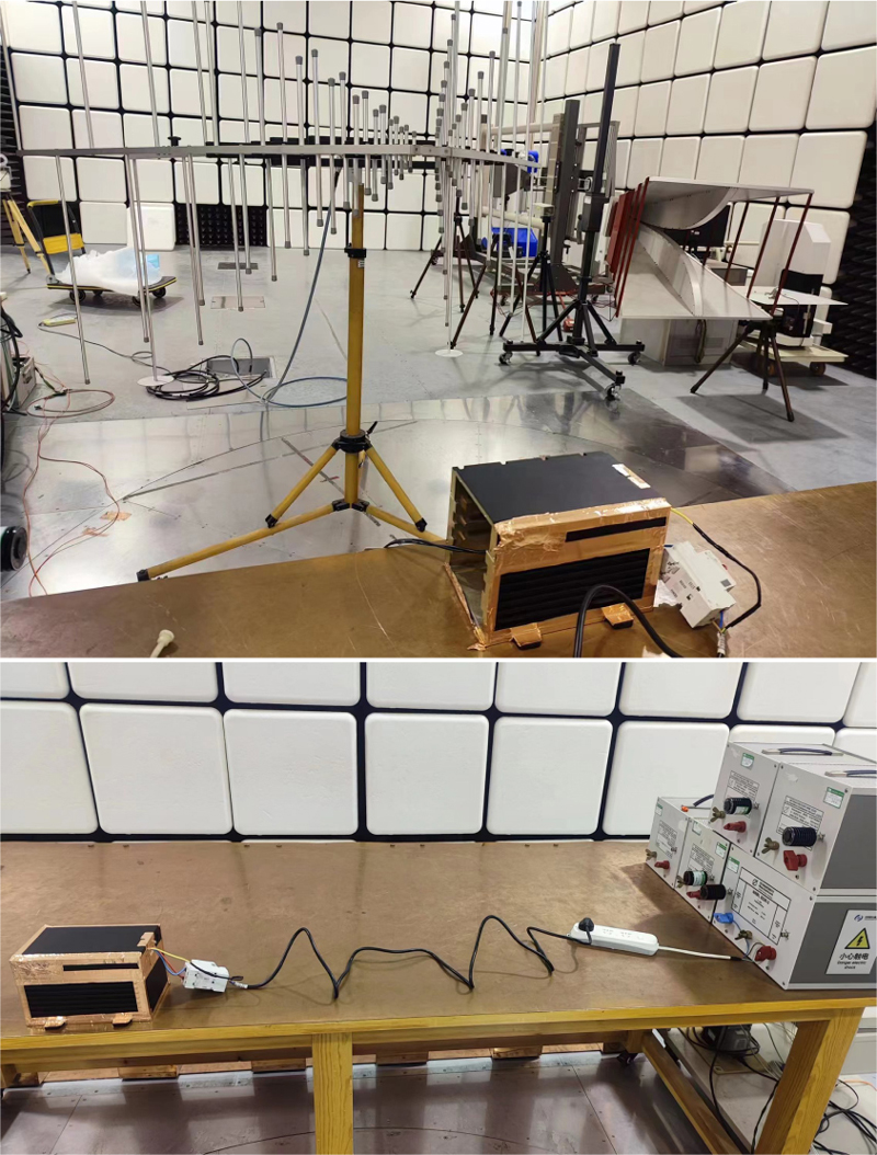
Figure 25: The experiment scene.
VII. EXPERIMENTAL VERIFICATION OF PROTECTION DESIGN
The electromagnetic experiment for the VPX chassis is performed to validate the simulation results. The experiment scene is shown in Fig. 25. The VPX chassis with protection design is placed in the electromagnetic test environment. Limited to the actual experimental platform, the operating frequencies of electric field intensity test are lower than 1 GHz. The type of excitation signal is sinc. The radiation antenna is in the vertical polarization mode. The external electric field intensity of the VPX chassis is set to 20 v/m, and the radiated power values of the source signal at different frequency points of 300 MHz, 400 MHz, 500 MHz, 600 MHz, 800 MHz, and 1000 MHz are measured, which are fixed in the subsequent experiment. Then, the sensor probe is placed inside the chassis and the electric field intensities at different operating frequencies are measured. The measurement results of the electric field intensity of the VPX chassis are recorded in Table 2.
Table 2: Measurement results of the electric field intensity of the VPX chassis
| Operating Frequency | Excitation Signal Radiated Power (dBm) | External Electric Field Intensity of the Chassis (v/m) | Interior Electric Field Intensity of the Chassis (v/m) |
|---|---|---|---|
| 300 MHz | -24.7 | 20 | 1.0 |
| 400 MHz | -24.6 | 1.0 | |
| 500 MHz | -23.0 | 6.0 | |
| 600 MHz | -23.6 | 3.0 | |
| 800 MHz | -23.3 | 4.0 | |
| 1000 MHz | -24.4 | 2.0 |
For comparison, the electromagnetic simulations with CST are performed to obtain the interior electric field intensity of the VPX chassis under the same conditions of operating frequencies and excitation signal. At different frequency points of 300 MHz, 400 MHz, 500 MHz, 600 MHz, 800 MHz, and 1000 MHz, the simulation curves of the interior electric field intensity in time-domain are shown in Fig. 26.
The accuracy of the electromagnetic simulation model can be calculated as
| (4) |
where indicates the experimental value of the interior electric field intensity of the VPX chassis, and indicates the simulation value of the interior electric field intensity of the VPX chassis. With the simulation result and experimental result, the accuracy calculation of the simulation model under such plane wave radiation is listed in Table 3.
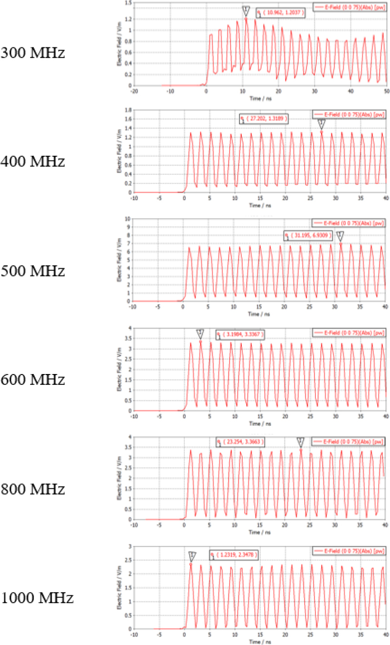
Figure 26: Simulation results of the interior electric field intensity of the VPX chassis.
Table 3: Accuracy of electromagnetic simulation model under plane wave radiation
| Operating Frequency | Interior Electric Field Intensity of VPX Chassis | Accuracy of Simulation Model (dB) | |
| Experiment Result (v/m) | Simulation Result(v/m) | ||
| 300 MHz | 1.0 | 1.20 | 13.98 |
| 400 MHz | 1.0 | 1.32 | 9.90 |
| 500 MHz | 6.0 | 6.93 | 16.19 |
| 600 MHz | 3.0 | 3.34 | 18.91 |
| 800 MHz | 4.0 | 3.37 | 16.05 |
| 1000 MHz | 2.0 | 2.35 | 15.14 |
Table 3 shows that the simulation result is consistent with the experimental result at different operating frequencies, and the accuracies of electromagnetic compatibility simulation model are higher than 9.90 dB, which can verify the simulation results and further demonstrate the feasibility and effectiveness of the protection design. To sum up, by adding protective measures on the air intake, air outlet, and trapdoor, as well as the gaps of the VPX chassis panels, the shielded VPX chassis has higher shielding effectiveness and can greatly reduce the electromagnetic coupling amounts of the important components in the VPX chassis. This is of great significance for the devices inside the VPX chassis to work normally under radiation electromagneticenvironment.
VIII. CONCLUSION
Electromagnetic compatibility should be considered as early as possible in the product design process to reduce the cost and cycle investment caused by later rectification. In this paper, the electromagnetic environment effects of the VPX chassis are analyzed via the CST simulation. The electromagnetic coupling characteristics are investigated under 20 v/m plane wave radiation. The coupling paths and the key positions of the electromagnetic protection in the VPX chassis are found, and the electromagnetic shielding effectiveness of the VPX chassis before and after protection design is evaluated. The simulation results are verified by the experiments. It provides guidance for the design of electromagnetic protective measures, and is helpful for reducing the cost of the actual electromagnetic protection design.
ACKNOWLEDGMENT
This work is supported by the Natural Science Foundation of Jilin Province under Grant 20220101100JC. The authors would like to thank the reviewers for their useful comments and suggestions.
REFERENCES
[1] I. Zheng and G. Wei, “New development of electromagnetic compatibility in the future: Cognitive electromagnetic environment adaptation,” 2021 13th Global Symposium on Millimeter-Waves & Terahertz (GSMM), Nanjing, China, pp. 1-3, 2021.
[2] Y. Wang, H. Sun, Q. Zhao, Y. Mao, and Q. Hou, “Study on capability verification test of electromagnetic pulse protection for aircraft,” 2022 Asia-Pacific International Symposium on Electromagnetic Compatibility (APEMC), Beijing, China, pp. 391-439, 2022.
[3] Q. F. Liu, S. Q. Zheng, Y. Zuo, H. Q. Zhang, and J. W. Liu, “Electromagnetic environment effects and protection of complex electronic information systems,” 2020 IEEE MTT-S International Conference on Numerical Electromagnetic and Multiphysics Modeling and Optimization (NEMO), Hangzhou, China, pp. 1-4, 2020.
[4] J. Jin, H. Xie, J. Hu, and W. Y. Yin, “Characterization of anti-jamming effect on the joint tactical information distribution system (JTIDS) operating in complicated electromagnetic environment,” 2014 International Symposium on Electromagnetic Compatibility, Gothenburg, Sweden, pp. 997-1000, 2014.
[5] Q. Li, W. Cao, J. Ding, J. Fang, J. Sun, and C. Guo, “Research on high-power electromagnetic effect and protective technology of electronic equipments,” 2022 IEEE 9th International Symposium on Microwave, Antenna, Propagation and EMC Technologies for Wireless Communications (MAPE), Chengdu, China, pp. 333-337, 2022.
[6] I. Xiao, Z. Song, J. Wang, and L. Wang, “Simulation analysis of electromagnetic shielding of electronic device chassis,” 2019 12th International Workshop on the Electromagnetic Compatibility of Integrated Circuits (EMC Compo), Hangzhou, China, pp. 91-93, 2019.
[7] Z. Jingchao, Q. Liyan, and C. Liqun, “Development of serial RapidIO high-speed data transmission based on VPX bus,” 2019 14th IEEE International Conference on Electronic Measurement & Instruments (ICEMI), Changsha, China, pp. 65-71, 2019.
[8] N. K. Singh, C. Fouziya, V. Kumar, and T. Venkatamuni, “A programmable, multimode operational 3U-VPX based digital transceiver & processing module for CIT-MKXIIA IFF,” 2023 International Conference for Advancement in Technology (ICONAT), Goa, India, pp. 1-5, 2023.
[9] M. Hua, N. Minxi, T. Anju, and M. Jianghong, “Power and signal integrity analysis of high-speed mixed-signal backplanes based on VPX,” 2018 IEEE Symposium on Electromagnetic Compatibility, Signal Integrity and Power Integrity (EMC, SI & PI), Long Beach, CA, USA, pp. 577-581,2018.
[10] N. Wu, D. G. Xie, D. E. Wen, and C. Wang, “Research on simulation and analysis of electromagnetic environment of cabinet in cabin,” 2011 4th IEEE International Symposium on Microwave, Antenna, Propagation and EMC Technologies for Wireless Communications, Beijing, China, pp. 524-527, 2011.
[11] Y. S. Wang, W. Q. Guo, W. Li, and Y. L Bian, “Research on strong electromagnetic protection technology of radar vehicle cockpit,” 2020 6th Global Electromagnetic Compatibility Conference (GEMCCON), XI’AN, China, pp. 1-8, 2020.
[12] Q. Q. Zheng, D. D. Wang, B. Xiong, and H. Y. Yan, “Investigation on ship LEMP protection design and test,” 2018 12th International Symposium on Antennas, Propagation and EM Theory (ISAPE), Hangzhou, China, pp. 1-4, 2018.
[13] Y. Yang, F. Zhu, N. Lu, and Y. Xiao, “Study on the electromagnetic interference of shielded cable in rail weighbridge,” Applied Computational Electromagnetics Society (ACES) Journal, vol. 37, no. 2, pp. 215-221, 2022.
[14] X. Hao, X. Meng, and X. Chen, “Effects mechanism of strong electromagnetic environment to equipment,” 2016 IEEE MTT-S International Microwave Workshop Series on Advanced Materials and Processes for RF and THz Applications (IMWS-AMP), Chengdu, China, pp. 1-4, 2016.
[15] Z. Yu and J. Wang, “Electromagnetic interference prediction in transient electromagnetic environment,” 2007 International Symposium on Electromagnetic Compatibility, Qingdao, China, pp. 221-224, 2007.
[16] H. Z. Zhao, G. H. Wei, and X. D. Pan, “Evaluation method of noise electromagnetic radiation interference effect,” IEEE Transactions on Electromagnetic Compatibility, vol. 65, no. 1, pp. 69-78, Feb. 2023.
[17] J. C. Zhou and X. T. Wang, “An efficient method for predicting the shielding effectiveness of an apertured enclosure with an interior enclosure based on electromagnetic topology,” Applied Computational Electromagnetics Society (ACES) Journal, vol. 37, no. 10, pp. 1014-1020, 2022.
[18] Z. Xu, Z. Zhang, B. Wu, H. Wang, X. Kong, and M. Wang, “A study of enclosed magnetic shielding room by simulation,” IEEE Transactions on Applied Superconductivity, vol. 31, no. 8, pp. 1-4, Art no. 2500404, Nov. 2021.
[19] A. Keshtkar, A. Maghoul, A. Kalantarnia, and A. Asad, “Design considerations to affect on shielding effectiveness for conductive enclosure,” IEICE Electronics Express, vol. 813388, no. 13, pp. 1047-1055, 2011.
[20] A. M. Dagamseh, Q. M. Al-Zoubi, and Q. Qananwah, “Modeling of electromagnetic fields for shielding purposes applied in instrumentation systems,” Applied Computational Electromagnetics Society (ACES) Journal, vol. 36, no. 8, pp. 1075-1082, 2021.
[21] Computer Simulation Technology (CST), http://www.cst.com.
[22] American National Standard Dictionary of Electromagnetic Compatibility (EMC) including Electromagnetic Environmental Effects (E3), ANSI C63.14-2014 (Revision of ANSI C63.14-2009) IEEE, 2014.
[23] M. Z. M. Jenu and F. A. Po’ad, “Electric and magnetic shielding effectiveness of metallic enclosures with apertures,” 2006 Asia-Pacific Microwave Conference, Yokohama, Japan, pp. 536-539, 2006.
[24] K. Cui, D. Shi, C. Sun, and X. Liu, “A compact and high-performance shielding enclosure by using metamaterial design,” Applied Computational Electromagnetics Society (ACES) Journal, vol. 36, no. 11, pp. 1484-1491, 2021.
[25] A. Keshtkar, A. Maghoul, A. Kalantarnia, and H. Hashempour, “Simulation of shielding effectiveness in low frequencies for conductive enclosure,” 2009 Second International Conference on Computer and Electrical Engineering, Dubai, United Arab Emirates, pp. 372-377, 2009.
[26] Z. Dou, J. Zhang, G. Wang, D. He, C. Liu, and T. Wang, “Electromagnetic shielding effectiveness of an absorber-like Carbonyl iron-FeNi double-layer composite,” Journal of Materials Engineering and Performance, vol. 31, no. 1, pp. 643-650, 2022.
BIOGRAPHIES

Hongkun Ni received the B.S. degree in communication engineering from Jilin University, Changchun, China, in 2020. He is currently pursuing the M.S. degree in communication engineering with Jilin University, Changchun, China. His current research interests include simulation analysis of electromagnetic environment effect, electromagnetic compatibility, and protection for electronic equipment.

Hong Jiang(corresponding author) received the B.S. degree in radio technology from Tianjin University, Tianjin, China, in 1989, the M.S. degree in communication and electronic system from Jilin University of Technology, Changchun, China, in 1996, and the Ph.D. degree in communication and information system from Jilin University, Changchun, China, in 2005. From 2010 to 2011, she had worked as a visiting research fellow at McMaster University, Canada. Currently, she is a professor at the College of Communication Engineering, Jilin University, China. Her research fields focus on electromagnetic compatibility, and signal processing for radar and wireless communications.

Xinbo Li received the B.S. degree in automation from Jilin University, Changchun, China, in 2002, the M.S. and Ph.D. degrees in control theory and control engineering from Jilin University, Changchun, China, in 2005 and 2009, respectively. Currently, he is a professor at the College of Communication Engineering, Jilin University, China. His research interests focus on electromagnetic protection, electromagnetic environment perception, intelligent signal recognition, and processing.

Qian Jia received the M.S. degree in electronic information engineering from North China Electric Power University, China. She is currently a senior engineer in Research and Development Department, China Academy of Launch Vehicle Technology, Beijing, China. She is engaged in integrated electronic system design of spacecraft. Her main research field is knowledge-based EMC design.

Xiaohui Wang received the M.S. degree in China. He is currently a researcher in Research and Development Department, China Academy of Launch Vehicle Technology, Beijing, China. He is engaged in long-term research on advanced integrated electronic optimization design.
ACES JOURNAL, Vol. 38, No. 11, 875–885
doi: 10.13052/2023.ACES.J.381106
© 2023 River Publishers