A High-gain Low-sidelobe Dual-polarized Broadband Array Antenna
Qi-Lei Zhou, Bo-Wen Zhang, Neng-Wu Liu, and Guang Fu
National Key Laboratory of Antennas and Microwave Technology
Xidian University, Xian, 710075, China
20021110068@stu.xidian.edu.cn, zhangbowenjp@gmail.com, nwliu@xidian.edu.cn, gfu@mail.xidian.edu.cn
Submitted On: May 27, 2023; Accepted On: December 13, 2023
ABSTRACT
In this paper, we present a dual-polarized broadband low side lobe array designed for operation in the Ku-band. The antenna array operates within the frequency range of 14.0 GHz to 15.2 GHz, covering a bandwidth of over 8%. To realize this wide operational frequency, we have selected broadband microstrip antenna elements as the units of the array. In order to fulfill the demanding criteria of broadband performance and low sidelobe characteristics, we introduce a broadband low-sidelobe feeding network based on a directional coupler design. This feeding network ensures connectivity with the antenna units, resulting in a voltage standing wave ratio (VSWR) 2 within the 14.0 GHz to 15.2 GHz frequency range. Furthermore, our antenna array achieves an array gain exceeding 21 dBi and keeps array sidelobes below -20 dB across the entire operating frequency band. Our research breakthrough addresses the critical design challenge of creating large-scale array antennas that combine broadband capabilities with high gain and minimal sidelobe interference.
Index Terms: broadband low sidelobe, dual-polarization, high-isolation, multi-layer.
I. INTRODUCTION
In recent years, the rapid advancement of electronic information technology has ushered in a compelling demand for enhanced antenna performance. Conventional single antennas are often inadequate in meeting the evolving requirements of modern electronic systems, which necessitate higher gain and broader bandwidth coverage. To address these challenges, array antennas have emerged as a prominent solution due to their ability to deliver increased gain. In addition to heightened gain, array antennas possess the distinct advantage of offering reduced sidelobes. The reduction in sidelobe radiation is of paramount importance in contemporary electronic systems, especially in the face of ever-growing electromagnetic complexity. Lower sidelobes equate to improved anti-interference capabilities, which are increasingly critical in ensuring the reliable operation of electronic systems within our intricate and crowded electromagnetic environment.
In the realm of synthetic array networks, there exist two predominant feeding configurations: series feed and parallel feed. Both configurations can achieve low sidelobe distributions through differential amplitude power divisions [1–2]. Arrays that utilize a series feed configuration present notable advantages such as high efficiency and structural simplicity. Nonetheless, intrinsic limitations in their feed structures typically confine them to a working bandwidth of less than 3% [3–7]. For applications necessitating broader bandwidths, it becomes imperative to employ a composite network that utilizes parallel feeding mechanisms [8–12]. Yet, as the scale of the array expands and sidelobe constraints become more stringent, the imperative to meet specified power ratios demands the use of T-type power dividers with larger power divisions. Notably, these T-type power dividers, when designed for larger power ratios, inherently possess wider microstrip line widths. This presents a significant design challenge and often results in compromised stability. Consequently, the realization of a wideband, high-gain, low-sidelobe array remains an intricate task.
Aside from the synthesis network with low side lobes for broadband, the broadband antenna unit has also become a key device. As resonant antennas, microstrip antennas inherently lack broadband characteristics due to their physical features. Traditional methods to widen the bandwidth, such as increasing thickness, coupling feed, and adding parasitic units, have proven effective. However, with the recent in-depth research on the resonant technology of microstrip antennas, multi-mode has emerged as a new method to effectively widen the bandwidth [12–18]. This approach can achieve various novel effects, such as achieving broader characteristics at a lower profile and manipulating radiation patterns.
In this paper, we introduce a high-power specific power divider designed around a directional coupler. This novel design attains a directional bandwidth exceeding 8%, maintains a sidelobe suppression of less than -25 dB within the operational frequency range, and exhibits an array gain surpassing 21 dB. Consequently, it enables the realization of a wideband, low-sidelobe, high-gain array, holding significant importance.
II. GEOMETRY AND WORING PRINCIPLE
The schematic representation of the antenna’s overall structure is presented in Fig. 1. This high-gain, wideband, and low-sidelobe antenna array comprises a dual-polarized antenna array integrated with a wideband, low-sidelobe synthesis network. The inter-element separation in the array is set at 14 mm, resulting in a compact array with overall dimensions measuring 22062 mm.
In order to extend the operational bandwidth of the microstrip antenna, a coupling feeding technique is employed within the antenna’s radiation layer. Fabrication of the antenna, as well as the dual-polarization wideband, low-sidelobe array feed network, is achieved through the utilization of multilayer media printing technology. The antenna is printed on two layers of Rogers 4350B substrate, each with distinct thicknesses of 0.724 mm and 0.508 mm, respectively. Additionally, two layers of Rogers 4450F substrate, each 0.1 mm thick, are utilized for adhesion purposes.
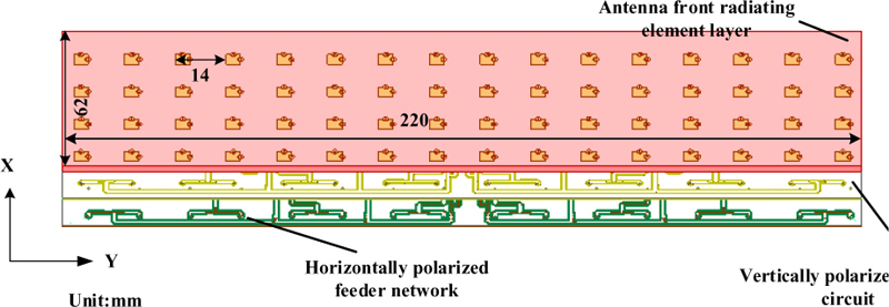
Figure 1: Configuration of the proposed dual-polarized broadband low-sidelobe array antenna.
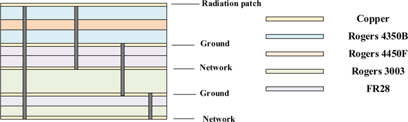
Figure 2: Schematic diagram of multilayer laminated structure.
To optimize gain performance, the vertically polarized wideband low sidelobe feed network is fabricated on a 0.254 mm Rogers 3003 substrate, securely affixed between two layers of 0.1 mm FR28 substrate. In addition, the horizontally polarized wideband network is manufactured on a 0.127 mm Rogers’s 3003 substrate, firmly attached to a single layer of 0.1 mm FR28 substrate.
In line with this construction methodology, the overall configuration of the wideband, high-gain, and low-sidelobe antenna, as proposed in this paper, can be segmented from top to bottom into distinct layers: the antenna radiation layer, a metallic base plate, the vertically polarized feed network, another metallic base plate, and the horizontally polarized feed network. The stratified composition of this multilayer board is visually depicted in Fig. 2.
A. Analysis of wideband antenna unit
Square patches serve as radiators, and their overall side length is illustrated in Fig. 3. Coupled feeders are employed to expand the operational bandwidth, and feed probes are utilized to connect the antenna radiation elements with the feed network. In order to validate the antenna element design, simulations are conducted on the wideband array antenna element. The simulated S-parameters and the radiation pattern of the broadband antenna unit are depicted in Figs. 4 and 5, respectively.
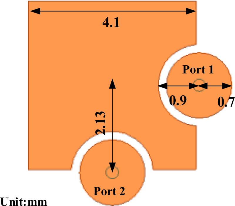
Figure 3: Schematic diagram of the 2D structure antenna unit.
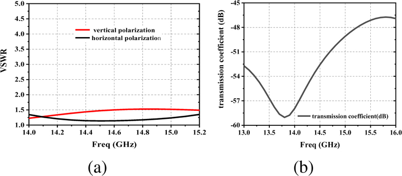
Figure 4: (a) Antenna unit VSWR and (b) isolation between the dual-polarized ports.
B. Analysis of wideband low sidelobe network
The wideband low sidelobe synthesis network is configured for parallel feeding, employing the Taylor low sidelobe distribution. To attain ultra-low sidelobes and a heightened power ratio, the conventional T-junction power splitter’s impedance conversion section necessitates an exceedingly fine high-impedance microstrip line, which may pose practical challenges. As delineated in Fig. 6, we introduce a novel 16-unit wideband low-sidelobe synthesis network based on a two-stage directional coupler.
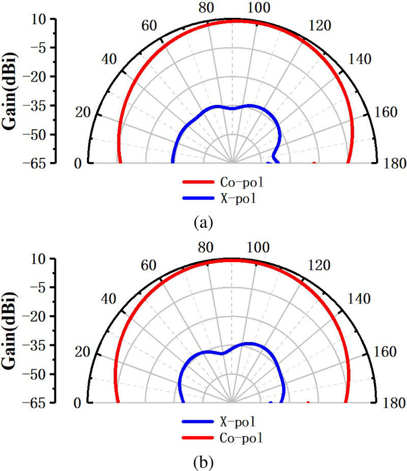
Figure 5: The radiation patterns of the antenna unit at the center frequency points: (a) Vertical polarization 14.0 GHz E plan antenna pattern and (b) horizontal polarization 14.0 GHz E plan antenna pattern.
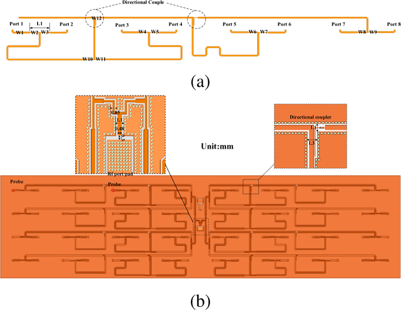
Figure 6: Schematic diagram of half of a 16-unit synthetic horizontal polarization network based on directional coupler.
To further optimize the performance of the wideband low sidelobe feed network and mitigate coupling effects between transmission lines, we implement a coupling elimination strategy using metal holes. The interface diagram for the feed network, catering to both vertical and horizontal polarizations, is presented below. Short-circuit pins are precisely positioned at a distance of 0.31 mm from the signal transmission lines, and the surrounding dimensions around the feed position are also provided.
Additionally, due to spatial constraints, feed synthesis networks with differing polarizations are segregated into distinct layers. Concurrently, the vertical polarization wideband low sidelobe feed network is positioned as a strip line beneath the antenna array radiation layer, while the horizontal polarization wideband low sidelobe feed network is located as a microstrip line at the lowermost layer.
Table 1: Value of the corresponding parameter in the horizontal polarization feed network
| Parameter | Value (mm) | Parameter | Value (mm) |
|---|---|---|---|
| L1 | 6.28 | W7 | 0.16 |
| W1 | 0.48 | W8 | 0.29 |
| W2 | 0.27 | W9 | 0.18 |
| W3 | 0.21 | W10 | 0.28 |
| W4 | 0.29 | W11 | 0.18 |
| W5 | 0.19 | W12 | 0.1 |
| W6 | 0.31 |
Table 2: Value of the corresponding parameter in the horizontal polarization feed network
| Parameter | Value (mm) | Parameter | Value (mm) |
|---|---|---|---|
| L1 | 6.28 | W7 | 0.16 |
| W1 | 0.48 | W8 | 0.29 |
| W2 | 0.27 | W9 | 0.18 |
| W3 | 0.21 | W10 | 0.28 |
| W4 | 0.29 | W11 | 0.18 |
| W5 | 0.19 | W12 | 0.1 |
| W6 | 0.31 |
Drawing upon the principles of unequal amplitude power splitting and directional coupling, we have devised a wideband low sidelobe feed network tailored for horizontal and vertical polarization. The specific dimensional parameters are meticulously documented in Tables 1 and 2. It’s noteworthy that the vertical polarization feed network exhibits a comparable topology to its horizontal polarization counterpart, albeit with distinct width specifications, meticulously delineated in Table 2
In pursuit of the design’s validation for the comprehensive low sidelobe feed network, we have undertaken simulation and verification efforts, focusing on half of the 16-unit low sidelobe composite network. The resulting S-parameter data is visually represented in Figs. 7 and 8.
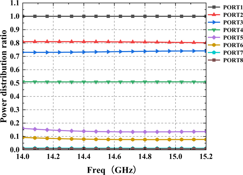
Figure 7: Power distribution ratio of half of a 16-unit synthetic horizontal polarization network based on directional coupler.
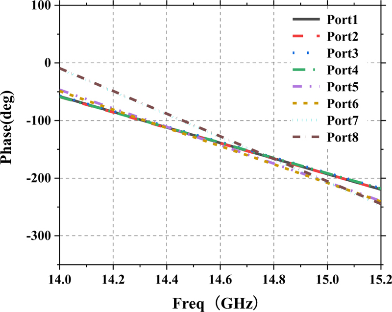
Figure 8: Power distribution ratio of half of a 16-unit synthetic horizontal polarization network based on directional coupler.
The wideband low sidelobe feed network, utilizing a directional coupler, exhibits consistent and stable power distribution ratios across a broad bandwidth. This facilitates the realization of high-gain, wideband, low sidelobe technology. Notably, the achieved power distribution ratio effectively adheres to the amplitude distribution specifications prescribed by the Taylor distribution. Moreover, it maintains consistent phase characteristics over the wide frequency spectrum, highlighting its potential for broadband low sidelobe performance. It’s worth noting that the design principles governing the vertical polarization wideband feed network closely parallel those of the horizontal polarization network.
C. Analysis of wideband low sidelobe network
By analyzing both the microstrip radiation unit and the broadband low sidelobe feed network, the combined effect of the distributed amplitude-phase characteristics of the broadband low sidelobe feed network enables the microstrip radiation unit to exhibit high-gain, broadband, low sidelobe characteristics within the specified frequency band.
III. RESULTS AND EXPERIMENTAL VALIDATION
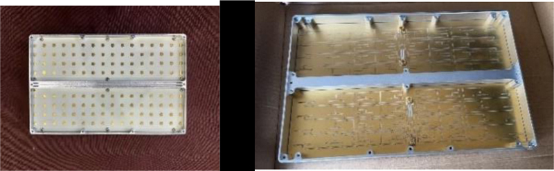
Figure 9: Photograph of the fabricated antenna in Fig. 1.
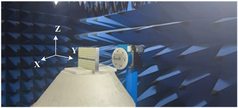
Figure 10: Photograph of measuring the fabricated antenna in Fig. 1.
Based on the operational principles of the antenna unit and the low sidelobe feed synthesis network, the connection of the antenna to the feed network via the feed probe yields a synthesized beam for the array. This beam exhibits a low sidelobe direction pattern across a broad spectrum. To rigorously validate the aforementioned design, comprehensive simulations and processing of the array antenna are performed.
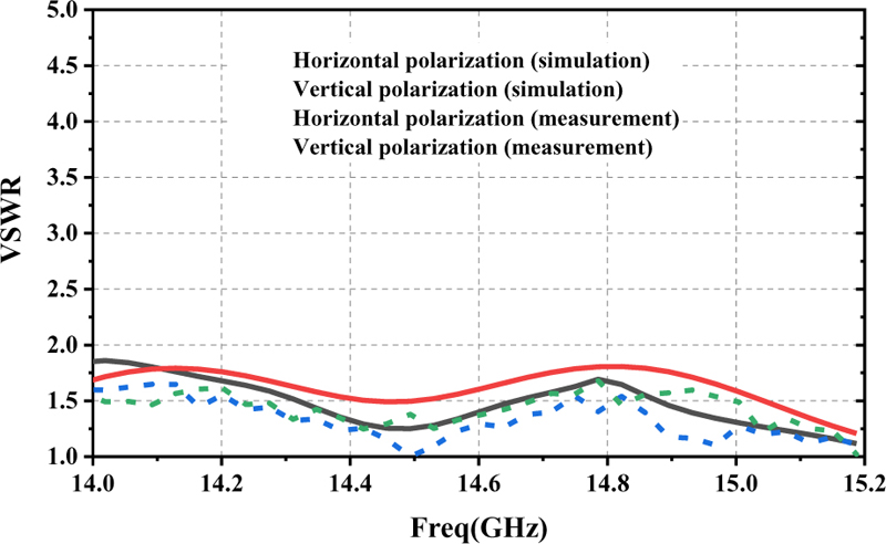
Figure 11: Simulation and measurement of wideband low side lobe array antenna voltage standing wave ratio.
Figure 9 shows a photograph of the prepared antenna, while Fig. 10 illustrates the measurement environment utilized during the antenna testing process. The initial evaluation of the proposed antenna involves both simulation and voltage standing wave measurements, as presented in Fig. 11. Notably, the simulation results closely align with the measured data, demonstrating good agreement.
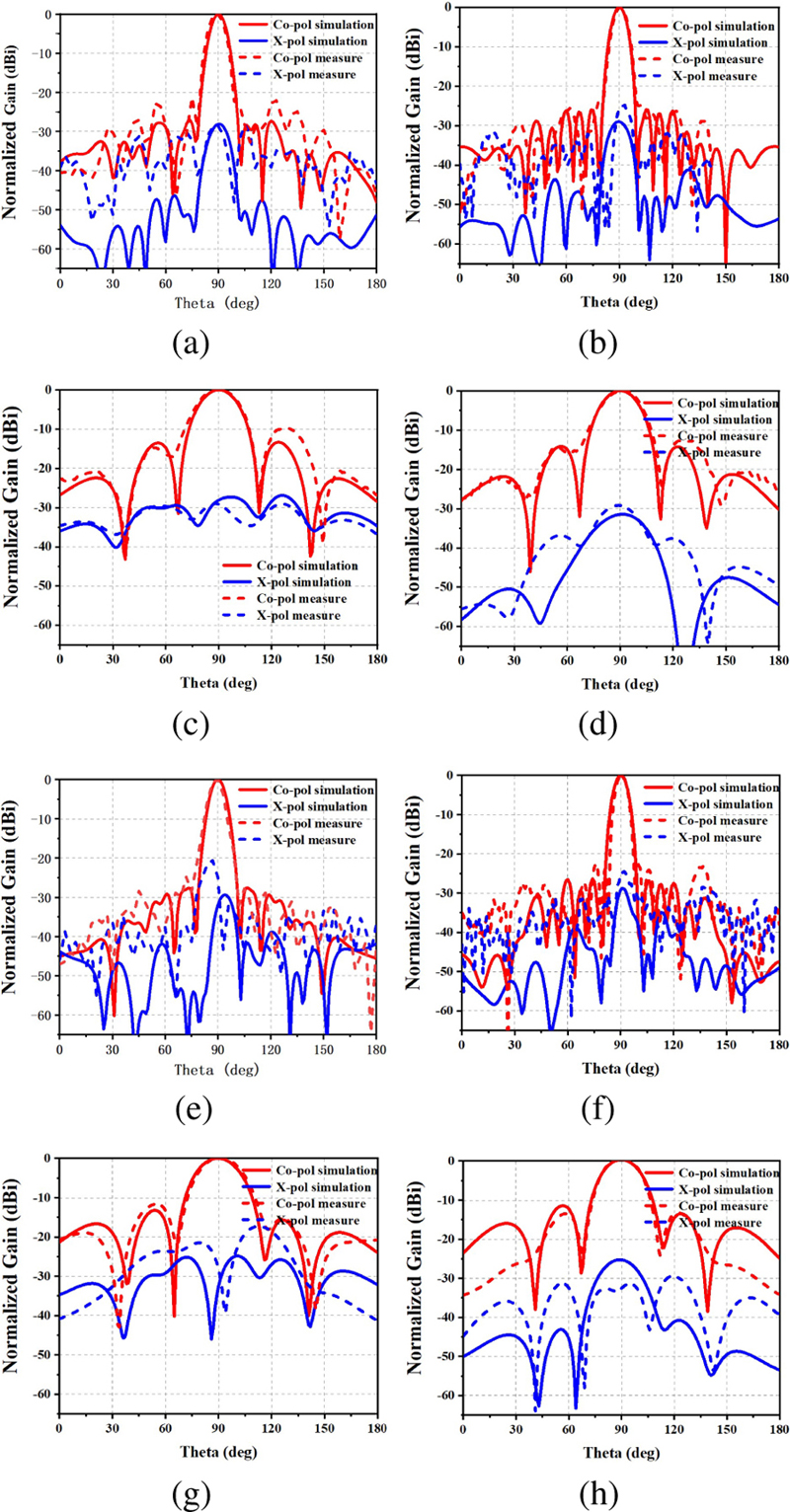
Figure 12: (a) horizontal polarization radiation pattern of the antenna array at 14.0 GHz in XOY plane, (b) horizontal polarization radiation pattern of the antenna array at 15.2 GHz in XOY plane, (c) horizontal polarization radiation pattern of the antenna array at 14.0 GHz in XOZ plane, (d) horizontal polarization radiation pattern of the antenna array at 15.2 GHz in XOZ plane, (e) vertical polarization radiation pattern of the antenna array at 14.0 GHz in XOY plane, (f) polarization the radiation patterns of the antenna array at 15.2 GHz in XOY plane, (g) vertical polarization radiation pattern of the antenna array at 14.0 GHz in XOZ plane, and (h) vertical polarization radiation pattern of the antenna array at 15.2 GHz in XOZ plane.
Furthermore, the measured results indicate that the antenna possesses an impedance bandwidth (VSWR ) of approximately 8%, spanning the frequency range from 14 GHz to 15.2 GHz. Within this frequency band, sidelobes are effectively suppressed to levels lower than -25 dB. The radiation patterns of the proposed wideband, low sidelobe array antenna are visualized in Fig. 12. In this figure, subfigures (a) and (b) depict the 14 GHz vertical polarization YOZ-plane radiation pattern, (c) and (d) illustrate the 14GHz vertical polarization XOZ-plane radiation pattern, while (e) and (f) portray the horizontal polarization YOZ-plane radiation pattern at 15.2 GHz. Additionally, (g) and (h) exhibit the horizontal polarization XOZ-plane radiation pattern. These visualizations underscore the antenna array’s capacity to maintain ultra-low sidelobes over a broad bandwidth, with high consistency observed between antenna testing and simulation results.
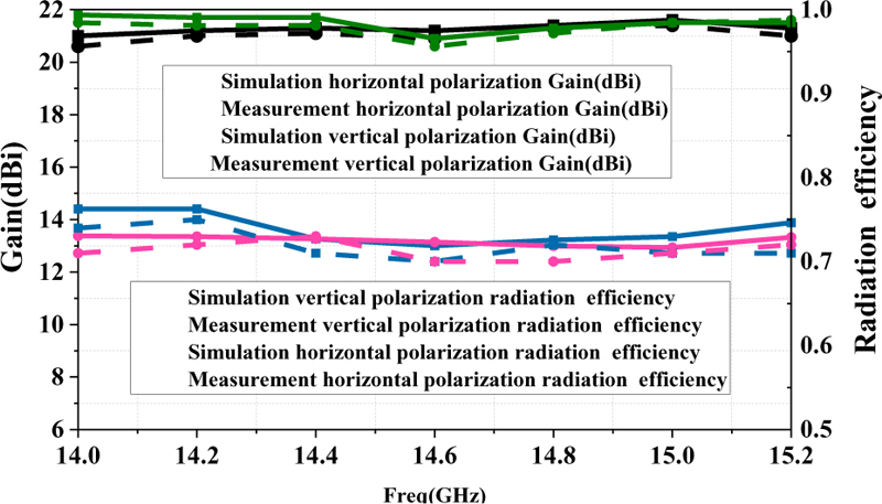
Figure 13: Simulation and measurement gain of proposed array antenna.
Moreover, it’s important to note that the antenna achieves a maximum gain exceeding 21 dB within this operational frequency band, and this gain behavior in both simulation and testing is depicted in Fig. 12.
In addition, the array antenna exhibits a gain of over 20 dB within the 14 GHz-15.2 GHz frequency range. The measurement results closely align with the simulation outcomes, demonstrating a strong correspondence between them.
Finally, Table 3 presents a comprehensive summary of performance metrics for various antenna arrays. The data reveals that this antenna configuration attains a broader bandwidth while operating at a high-gain condition compared to previous research efforts.
Table 3: Comparison with previous
| Ref. | Gain(dB) | Sidelobe Level(dB) | Bandwidth | Feed Network Mode | Radiation Efficiency | Array Size |
| [1] | 16.0 | -24.2 | 1% | Series | 67.0% | 126 |
| [2] | 9.0 | -26.0 | 13% | Parallel | Less than 50% | 16 |
| [3] | 20.0 | -28.0 | 1% | Series | Unknown | 168 |
| [4] | 13.0 | -28.0 | Series | 75% | 33 | |
| [5] | 19.0 | -23.0 | Series | Unknown | 88 | |
| [6] | 23.0 | -20.0 | Series | 85% | 224 | |
| [7] | 22.0 | -20.0 | 2% | Series | Unknown | 68 |
| [8] | 14.0 | -20.0 | 22% | Parallel | 45.1% | 18 |
| [9] | 15.4 | -18.0 | 23% | Parallel | 50.0% | 18 |
| [10] | 15.5 | -18.6 | 18% | Parallel | Unknown | 18 |
| [11] | 15.3 | -30.0 | 14% | Parallel | Unknown | 44 |
| [12] | 15.2 | -19.2 | 46% | Parallel | Unknown | 18 |
| Prop. | 21.0 | -25.0 | 8% | Parallel | 72% | 164 |
IV. CONCLUSION
In this paper, a novel dual-polarized broadband low-sidelobe array antenna is proposed, in which the antenna elements are integrated with a novel directional coupler-based broadband low-sidelobe synthesis network through a multilayer board process. Over 21 dB of gain and less than 25 dB of side lobes can be achieved in over 8% of the bandwidth.
ACKNOWLEDGMENT
This work is supported by the National Natural Science Foundation of China under General Program (62271364), Key Research and Development Program of Shaanxi (Program No. 2023-GHZD-45), Fundamental Research Funds for the Central Universities (ZYTS23145), University of Macau (0080/2021/A2), and Special Grant CPG2023-00020-FST. (Corresponding author: Guang Fu)
REFERENCES
[1] H. Khalili, K. Mohammadpour-Aghdam, S. Alamdar, and M. Mohammad-Taheri, “Low-cost series-fed microstrip antenna arrays with extremely low sidelobe levels,” IEEE Transactions on Antennas and Propagation, vol. 66, no. 9, pp. 4606-4612, Sep. 2018.
[2] A. Falahati, M. NaghshvarianJahromi, and R. M. Edwards, “Wideband fan-beam low-sidelobe array antenna using grounded reflector for DECT, 3G, and ultra-wideband wireless applications,” IEEE Transactions on Antennas and Propagation, vol. 61, no. 2, pp. 700-706, Feb.2013.
[3] J. Qian, H. Zhu, M. Tang, and J. Mao, “A 24 GHz microstrip comb array antenna with high sidelobe suppression for radar sensor,” IEEE Antennas and Wireless Propagation Letters, vol. 20, no. 7, pp. 1220-1224, July 2021.
[4] R. Chopra and G. Kumar, “Series-fed binomial microstrip arrays for extremely low sidelobe level,” IEEE Transactions on Antennas and Propagation, vol. 67, no. 6, pp. 4275-4279, June2019.
[5] Y. Chang, Y.-C. Jiao, L. Zhang, G. Chen, and X. Qiu, “A K-band series-fed microstip array antenna with low sidelobe for anticollision radar application,” 2017 Sixth Asia-Pacific Conference on Antennas and Propagation (APCAP), Xi’an, China, pp. 1-3, 2017.
[6] J. Yue, C. Zhou, K. Xiao, L. Ding, and S. Chai, “W-band low-sidelobe series-fed slot array antenna based on groove gap waveguide,” IEEE Antennas and Wireless Propagation Letters, vol. 22, no. 4, pp. 908-912, Apr. 2023.
[7] Y. Liu, G. Bai, and M. C. E. Yagoub, “A 79GHz series fed microstrip patch antenna array with bandwidth enhancement and sidelobe suppression,” 2020 International Conference on Radar, Antenna, Microwave, Electronics, and Telecommunications (ICRAMET), Tangerang, Indonesia, pp. 155-158, 2020.
[8] W. Ma, W. Cao, R. Hong, J. Jin, and B. Zhang, “Planar broadband higher-order mode millimeter-wave microstrip patch antenna array with low sidelobe level,” IEEE Antennas and Wireless Propagation Letters, vol. 20, no. 12, pp. 2225-2229, Dec. 2021.
[9] J. Wang, Y. Li, and J. Wang, “A low-profile dual-mode slot-patch antenna for 5G millimeter-wave applications,” IEEE Antennas and Wireless Propagation Letters, vol. 21, no. 3, pp. 625-629, Mar. 2022.
[10] C. Chen, J. Chen, and X. Zhu, “Design of a low profile and low sidelobe metasurface antenna array for millimeter-wave application,” 2022 Asia-Pacific Microwave Conference (APMC), Yokohama, Japan, 2022.
[11] Y. Dong, X. Cai, and G. Wen, “Circularly polarized antenna array with suppressed sidelobes for electronic toll collection,” IEEE Antennas and Wireless Propagation Letters, vol. 21, no. 5, pp. 988-992, May 2022.
[12] G. Bai, Y. Liu, and C. Liao, “A broadband high gain microstrip yagi antenna array for mm-wave communication systems,” 2020 International Conference on Radar, Antenna, Microwave, Electronics, and Telecommunications (ICRAMET), Tangerang, Indonesia, pp. 180-183, 2020.
[13] L. Zhu and N. Liu, “Multimode resonator technique in antennas: A review,” Electromagnetic Science, vol. 1, no. 1, article no. 0010041, 2023.
[14] N.-W. Liu, L. Zhu, and W.-W. Choi, “Differential-fed microstrip patch antenna with bandwidth enhancement under operation of TM10 and TM30 modes,” IEEE Transactions on Antennas and Propagation, vol. 65, no. 4, pp. 1607-1614, 2017.
[15] N.-W. Liu, L. Zhu, W.-W. Choi, and X. Zhang, “A low-profile aperture-coupled microstrip antenna with enhanced bandwidth under dual resonance,” IEEE Transactions on Antennas and Propagation, vol. 65, no. 3, pp. 1055-1062, 2017.
[16] N.-W. Liu, L. Zhu, W.-W. Choi, and J.-D. Zhang, “A novel differential-fed patch antenna on stepped-impedance resonator with enhanced bandwidth under dual-resonance,” IEEE Transactions on Antennas and Propagation, vol. 64, no. 11, pp. 4618-4625, 2016.
[17] N.-W. Liu, L. Zhu, W.-W. Choi, and X. Zhang, “Wideband shorted patch antenna under radiation of dual-resonant modes,” IEEE Transactions on Antennas and Propagation, vol. 65, no. 6, pp. 2789-2796, June 2017.
[18] N.-W. Liu, L. Zhu, W.-W. Choi, and X. Zhang, “A low-profile differential-fed patch antenna with bandwidth enhancement and sidelobe reduction under operation of TM10 and TM12 modes,” IEEE Transactions on Antennas and Propagation, vol. 66, no. 9, pp. 4854-4859, 2018.
BIOGRAPHIES

Qi-lei Zhou was born in Shaanxi, China, in September 1996. He received the B.S. degree in electronic information Technology from Xidian University, Xi’an, China, in 2019, where he is currently pursuing the Ph.D. degree. His current research interests include broadband miniaturized circularly polarized antenna and millimeter wave phased array.

Bo-Wen Zhang was born in Xi’an, China. He received the B.S. degree in electronic information Technology from Xidian University, Xi’an, China, in 2012. After that he received the M.E. in science and engineering from Toyo University, Tokyo, Japan. Since 2019, he is currently pursuing the Ph.D. degree from Xidian University. His current research interests include corrugated horn antenna beam-shaped array antenna and metamaterial applications in antenna

Neng-Wu Liu (Senior Member, IEEE) was born in Changde, China. He received the B.S. and M.E. degrees in electrical engineering from Xidian University, Xi’an, China, in 2012 and 2015, respectively, and the Ph.D. degree from the University of Macau, Macau, in 2017. Since 2018, he has been an Associate Professor with Xidian University. From 2019 to 2021, he was the UM Macao Post-Doctoral Research Fellow under the UM Macao Talent Program. His current research interests include designs of antenna theory, low-profile antenna, multimode antenna, wideband antenna, patch antenna, dielectric resonator antenna, circularly polarized antennas, filtering antenna, slot antenna, and phased array. Dr. Liu was a recipient of several academic awards, which includes the Best Student Paper Award in the 17th IEEE Macau/HK AP/MTT Postgraduate Conference and the Best Student Paper Award in 2017 National Conference on Antennas. He was also a recipient of the Outstanding Reviewer Award from the IEEE Transactions on Antennas and Propagation in 2020, 2021, and 2022; and the 2022 Macao Natural Science Awards (Second Prize) from the Science and Technology Development Fund (FDCT), Macau. He serves as an Associate Editor for IET Microwaves, Antennas and Propagation, IEEE Access, and Electronics Letters (IET).

Guang Fu received the B.S. and M.S. degrees in electromagnetic field and microwave technology from Xidian University, Xi’an, China, in 1984 and 1991, respectively.
He became a Professor with Xidian University, in 2001. His current research interests include theory and engineering of antenna and antenna array.
ACES JOURNAL, Vol. 39, No. 1, 24–30
doi: 10.13052/2024.ACES.J.390104
© 2024 River Publishers