CPW-Fed UWB-MIMO Antenna with Triple-band Notched and High Isolation using Double Y-shaped Decoupling Structure
Chenzhu Du and Huanchen Peng
Department of Electronics and Information Engineering
Shanghai University of Electric Power, Shanghai 200090, China
duchengzhu@163.com, 1106492100@qq.com
Submitted On: June 4, 2023; Accepted On: November 26, 2023
ABSTRACT
A ultra-wideband (UWB) multiple-input-multiple-output (MIMO) antenna using double Y-shaped decoupling structure with high isolation and triple notched-band is presented. The designed antenna composed of two orthogonally placed monopole elements, coplanar ground and double Y-shaped branch. The defected substrate structure is used to achieve miniaturization. By slotting successively C-shaped slot, semi-circular slot and rectangular slot on the radiation patch and the ground, achieved three notched bands at 3.5 GHz WiMAX, 5.25 GHz WLAN, and 7.5 GHz X-band. The proposed antenna can operate in range of 2.56-12 GHz with triple notched bands of 3.31-3.96 GHz, 4.58-5.67 GHz and 6.57-8.16 GHz. Considering all the results, it can be concluded that the antenna presented has a great performance in terms of good radiation, high isolation (24 dB), a low level ECC (0.01) and a high DG level (9.99), which proves the presented antenna has good prospect in UWB-MIMO systems.
Keywords: band-notched, DGS, defected substrate structure, high isolation, MIMO, SRR.
I. INTRODUCTION
Many scholars have studied ultra-wideband (UWB) technology for many years because by using this technology, wireless communication can be greatly improved in channel capacity and quality without having to increase the transmission power or spectrum. Although UWB technology has the advantages mentioned above, the application of UWB technology in other fields is limited because of its short transmission distance and limited signal transmission rate. Integration of UWB technology and multiple-input-multiple-output (MIMO) technology can overcome these shortcomings. MIMO antenna integrates at least two antenna elements on a dielectric substrate. Due to the limitation of substrate size, the two elements will be coupled with each other when they are close.
UWB covers the working bands of systems including WiMAX (3.3-3.7 GHz), WLAN (5.15-5.35 GHz), X-band (7.25-7.75 GHz) and so on. When UWB antenna works, it is easy to interfere with the above-mentioned systems, so suppressing overlapping band signals has become a research hotspot. The most effective method is to fabricate a UWB antenna with notched functions. [1–5] all achieve ultra-wide band. However, it is difficult and challenging to design an UWB-MIMO antenna that is small, has good anti-interference capabilities, a low coupling, and multiple notch characteristics.
Recently, MIMO technology has received a great attention. When MIMO technology is used in antenna design, it can help antennas achieve a high transmission rate and a stable transmission reliability. With MIMO technology, the signal is transmitted in multiple channels, thereby reducing multipath fading and increasing transmission capacity [6]. Many UWB-MIMO antennas are proposed in [6–22]. A circularly polarized MIMO antenna is designed in [6]. Although the impedance bandwidth is from 3.1-13.5 GHz, the antenna has a narrow axial ratio bandwidth from 4.7-6.1 GHz and is susceptible to be interfered by other useful bands. The slit slot is etched to improve isolation. In [7], a novel decoupling is used to improve isolation, which inter-element isolation is over 25 dB, but the function of notch is not realized. In [8], to get the notched-band characteristic a T-shaped slot is added; but it only realizes a notched band at 5.2 GHz, and the isolation just blow -15 dB. [9] proposed a MIMO antenna with the isolation higher than 20 dB. Loading a complementary CSRR produces two notched bands. [10] proposed a UWB-MIMO antenna which has two notch bands in 3.1-4.8 GHz and 5.1-6.3 GHz. The isolation which is enhanced by T-shape stubs is all better than 20 dB in the whole bands. [11] proposed an asymmetric coplanar strip fed MIMO antenna with two notched bands at WiMAX band and WLAN band. In [12], an increased level of isolation is achieved by introducing a defected ground structure. In order to generate triple notched bands, a C-shaped slot is introduced in the antenna, but the isolation is only less than 15 dB at working bands. Moreover, some three-notched bands antennas with microstrip feed are proposed in literatures [23–28]. The different EBG structures are used to realize three notched bands at WiMAX, X Band, and WLAN in [23, 24]. In [25], a novel 4-element UWB antenna was presented with three notch-band characteristics, and the orthogonal separated trapezoidal structure is used to enhance isolation. In [26], A MIMO antenna with three notches is designed, three notched bands are at 4.56, 7.25, and 9.08 GHz with great isolation of -22 dB. In [27], a UWB-MIMO antenna with three L-shaped slots is presented. In [28], a 44 UWB-MIMO antenna is designed with three notch frequencies at 3.72, 5.53 and 8.2 GHz.
This paper presents a CPW-fed UWB-MIMO antenna with a triple notched band and a double Y-shaped decoupling structure. There are two orthogonally placed monopole elements and a Y-shaped branch in this antenna. In summary, the innovations of the proposed antenna are as follows:(1) The defected substrate structure helps to achieve miniaturization;(2) The antenna has a filtering performance. The simulation and experiment results indicated that the antenna proposed in this paper could operate form 2.56-12 GHz except three notched bands from 3.31-3.96 GHz, 4.58-5.67 GHz, and 6.57-8.16 GHz;(3) The double Y-shaped stub is introduced to improve the isolation between the antenna ports better than 24 dB;(4) The coplanar waveguide (CPW) feeder is easy to be integrated in applications.
II. ANTENNA DESIGN AND ANALYSIS
A. Antenna Structure
The MIMO antenna design structure and physical photograph are shown in Fig. 1, it composed of two orthogonal circular monopole elements with tapered feed line, coplanar ground and Y-shaped branch. Firstly, the proposed antenna is fabricated on a 50500.8 mm FR-4 square substrate, with a dielectric constant = 4.4, and loss tangent = 0.02. Then, the substrate is cut to minimize the size of antenna (the reduced size is 31.04 % of the original size). By etching slots on the radiation patch and ground, triple notched bands are achieved. The slot length of L is usually /2 or /4, the formula is as follows in [30, 31]:
| (1) | ||
| (2) |
where C means the light speed, fcenter denotes the center frequency of the notch band, and eff represents the effective value of the dielectric constant. h is the thickness of the substrate. Wf and r are the width of feeder and relative dielectric constant of substrate. Detailed dimensions of designed MIMO antenna can be seen in Table 1.

Figure 1: Structure of the antenna: (a) Geometry of the antenna, (b) physical photograph of the antenna.
Table 1: Detailed dimensions of proposed antenna(mm)
| L1 | L2 | L3 | Ld | S1 |
| 8 | 22 | 5.3 | 9.1 | 36 |
| S2 | LZ1 | LZ2 | W1 | W2 |
| 16 | 13.6 | 3 | 14.5 | 5.6 |
| W3 | WF | WD | WZ1 | WZ2 |
| 0.5 | 0.2 | 3 | 5 | 0.6 |
| R0 | R1 | a1 | a2 | a3 |
| 8.7 | 3 | 60 | 57 | 1.6 |
B. Design process
HFSS-18 is used to design the proposed antenna. Figure 2 depicts the designed triple notched-band antenna. By adding slots on the ultra-bandwidth MIMO antenna, three notched bands are generated. The simulated S and S of four different antennas were shown in Fig. 3.
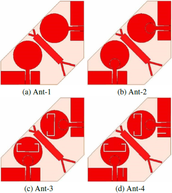
Figure 2: Design process of notched band MIMO antenna.
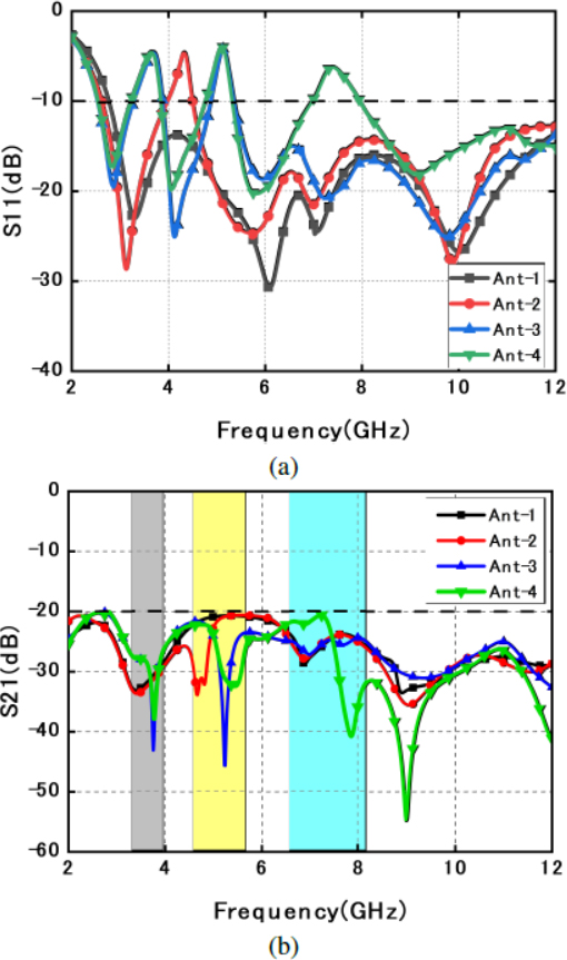
Figure 3: Effects of different slots on S-parameters: (a) S, (b) S.
The S of Ant-1 without slot is from 2.6 -12 GHz. In Ant-2, a notched band is generated from 3.98-4.70 GHz by adding an annular slot on the radiation patch. The notch frequency is set at 4.5 GHz. According to the formula (1) and (2), the approximate length of the annular slot is 40 mm. In Ant-3, another notch frequency is set at 3.3 GHz and the approximate length of the rectangular slot is 60 mm. Two slots interact with each other. Finally, two notched bands are generated from 3.11-3.79 GHz and 4.97-5.02 GHz by introducing C-shaped slot and rectangular slot on the radiation patch. By adding a rectangular slot on the ground of Ant-3, Ant-4 generates three notch frequencies from 3.11-3.79 GHz, 4.97-5.15 GHz and 6.80-7.97 GHz. At the same time, the S of all four antennas is less than -20 dB from 2.6 -12 GHz, which show all antennas have good performance.
C. Analysis of decoupling structure
A double Y-shaped branch is designed as an isolator in this paper. The antenna with and without double Y-shaped branch are shown in Fig. 4, and the influence of double Y-shaped structure on simulated S-parameter is shown in Fig. 5. The S of antenna without branch is less than -17 dB at all working bands, and the S of antenna with branch is below than -20 dB from 3-12 GHz, which show the branch is useful to enhance isolation.
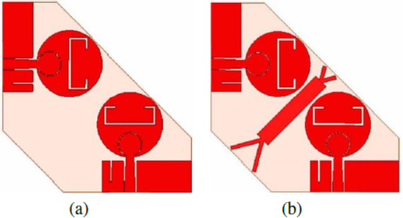
Figure 4: Diagram of the schematic: (a) Without branch, (b) with branch.
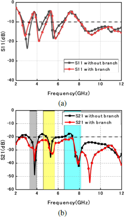
Figure 5: Effects of branch on S-parameters: (a) Sand (b) S.
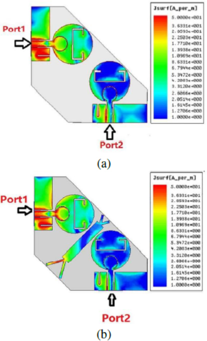
Figure 6: Surface current distributions at 7 GHz when Port 1 acts as the exciter and Port 2 connects 50 load: (a) Antenna with branch and (b) antenna without branch.
To understand the decoupling mechanism of the Y-shaped structure, Fig. 6 indicates the current distribution of antenna with branch and without branch at 7 GHz. In Fig. 6 (a), the current flows directly from one port to another, which leads to poor independence between antenna units. The coupling current of another antenna element can be reduced effectively, when the double Y-shaped structure is added in Fig. 6 (b).
Figure 7 shows simulated S-parameters of the antenna with single and double Y-shaped branch. In terms of S, the middle notch band is more accurate to filter 5.25 GHz WLAN. The S of antenna with single Y-shaped branch is less than -20 dB except the band of 2.24-3.06 GHz. In addition, the S of the antenna with double Y-shaped branch is less than -20 dB at all working bands, and the decoupling effect is more obvious with S less than -30 dB within 7.45-9.25 GHz.
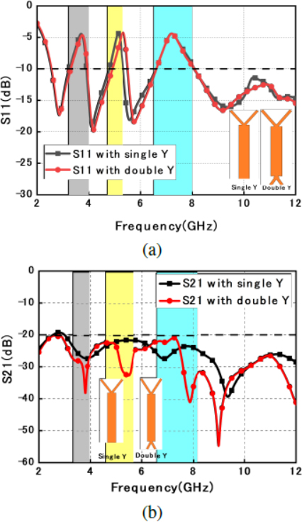
Figure 7: The S-parameters with single and double Y-shaped branch: (a) , (b) .
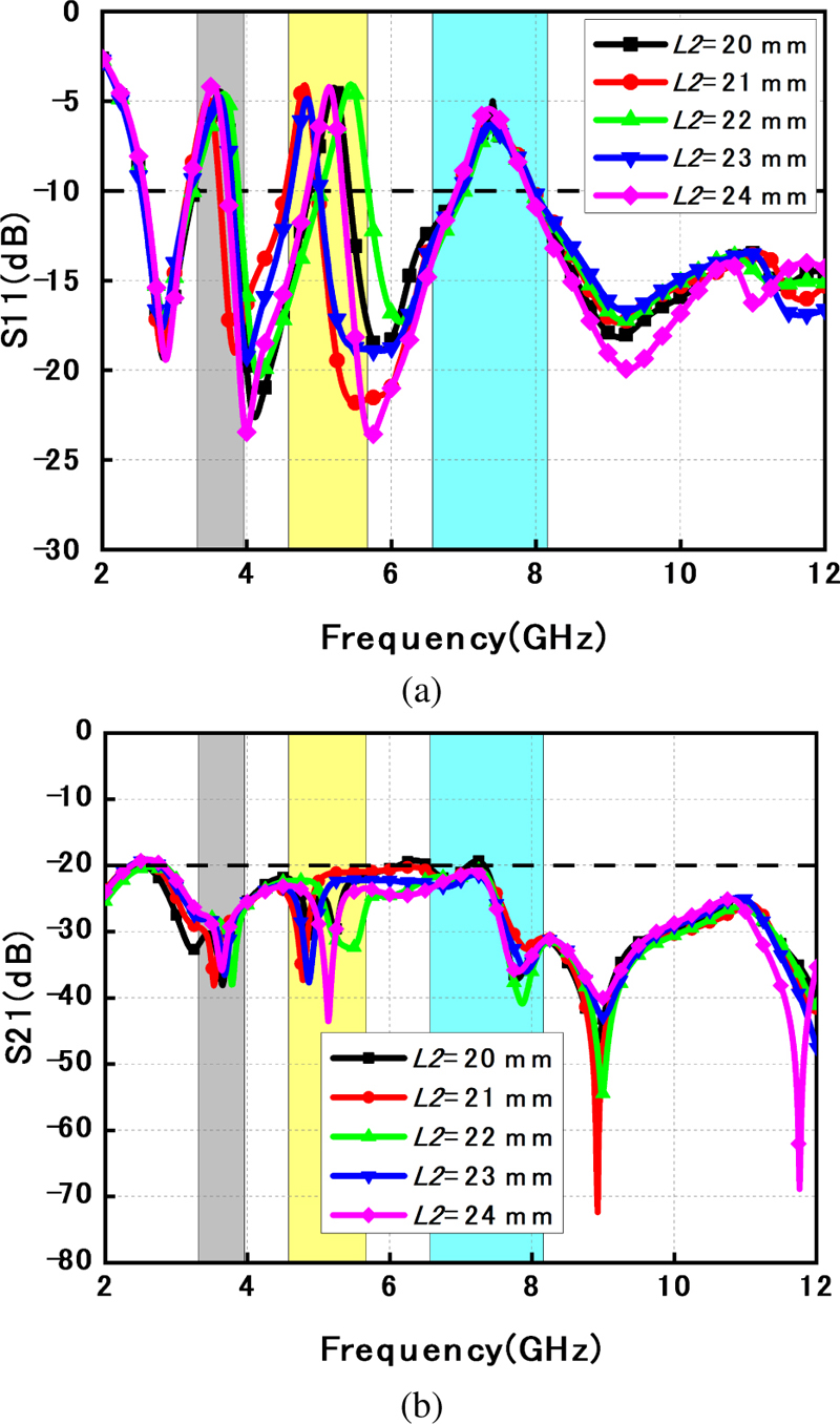
Figure 8: Simulated of different parameters: (a) S and(b) S.
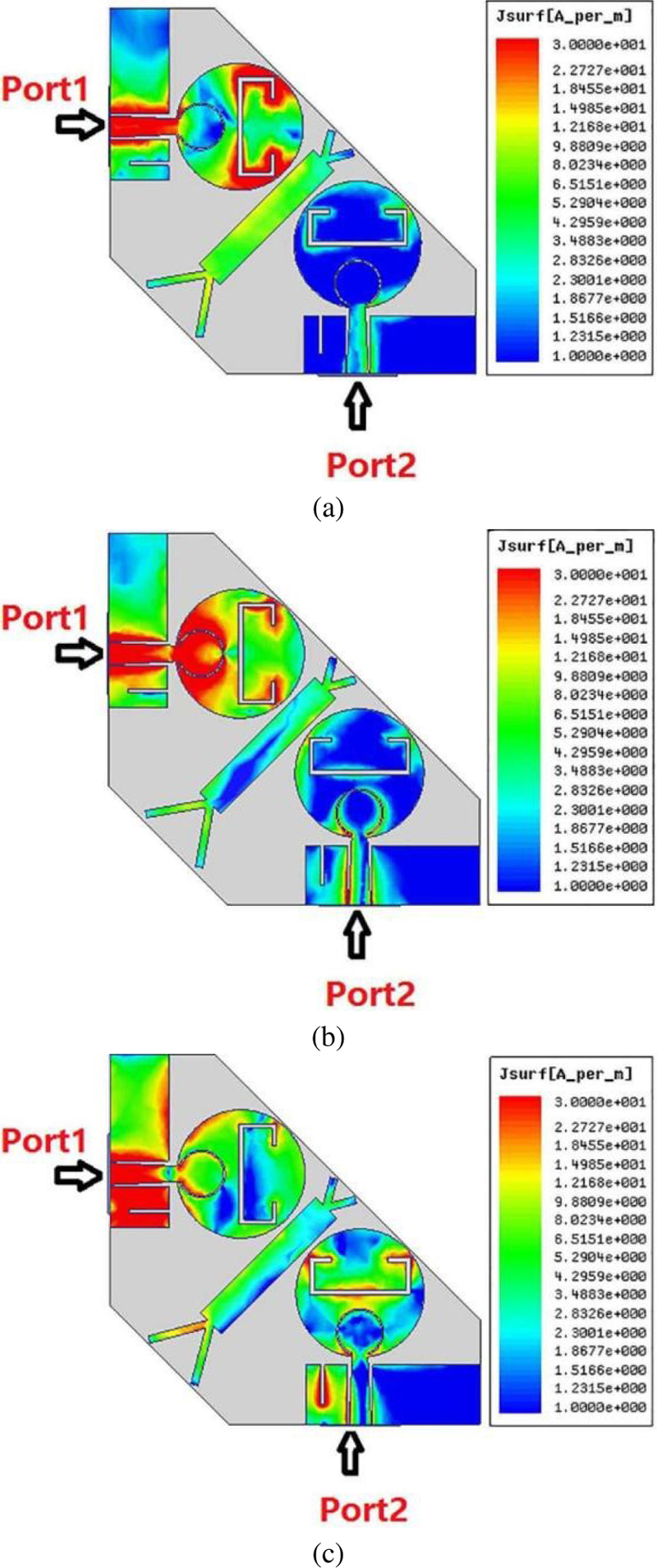
Figure 9: Simulated surface current distribution when Port 1 acts as the exciter: (a) 3.4 GHz, (b) 5.25 GHz, and (c) 7.5 GHz.
Simulated results of S and S with different lengths of L2 can be known in Fig. 8. L2 means the length of double Y-shaped structure, the change of L2 mainly affects the intermediate notched band. When the value of L2 is 22 mm, the intermediate notched band is wider than others, and S is less than -20 dB from 2-12 GHz.
D. The influence of slots
To further understand the influence of slots on antennas, Fig. 9 indicates the current distribution of the antenna at notched band center frequencies of 3.4, 5.25 and 7.5 GHz. In Fig. 9 (a), lots of current accumulates on the C-shaped slot which is added to generate a 3.4 GHz notch band. From Figs. 9 (b) and (c), annular slot and rectangular slot have the same effect as the C-shaped slot and produce 5.25 GHz notch band and 7.5 GHz notch band respectively.
III. RESULTS AND DISCUSSIONS
A. S-parameter
S-parameters were measured by an Agilent E8362B network analyzer. One port is excited during the measurement, while the other port is connected to 50-ohm load.
In Fig. 10, the measured S -10 dB (or VSWR 2) is from 2.56 to 12 GHz, except notched frequencies of 3.31-3.96 GHz, 4.58-5.67 GHz, and 6.57-8.16 GHz. Moreover, the measured S is lower than -24 dB in working band.
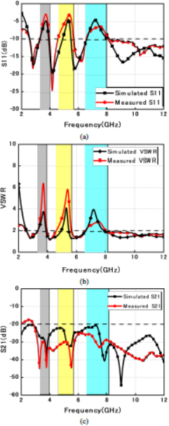
Figure 10: Comparisons between simulated and measured values of S-parameters: (a) S (b) VSWR, (c) S.
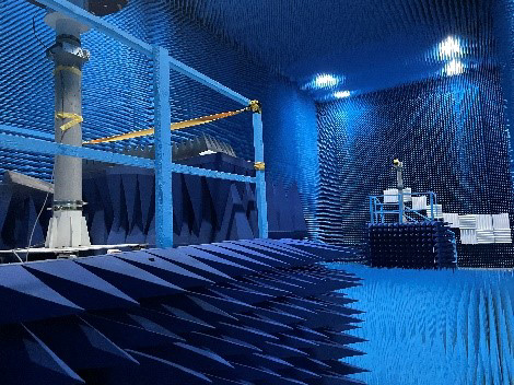
Figure 11: Antenna far field measurement setup.
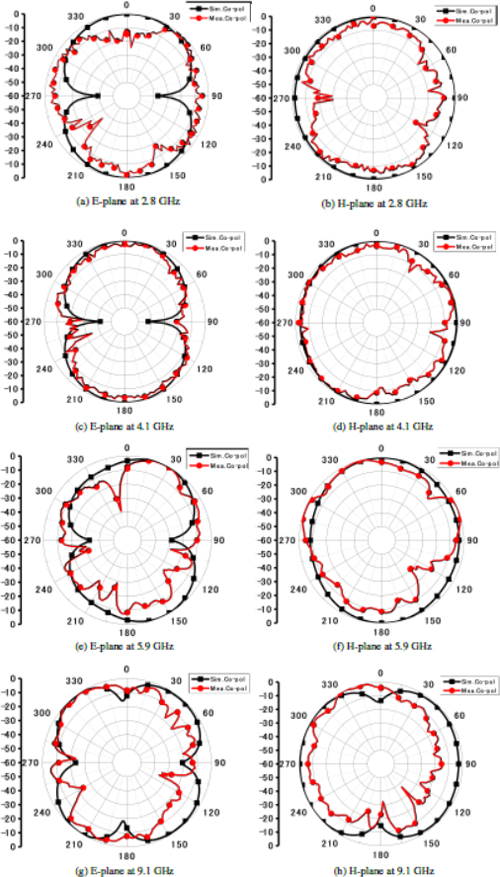
Figure 12: Radiation patterns.
B. Radiation pattern
The antenna radiation pattern measurement of far field is shown in Fig. 11. Radiation patterns at 2.8 GHz, 4.1 GHz, 5.9 GHz, and 9.1 GHz are depicted in Fig. 12. The antenna exhibits omnidirectional radiation in H-plane and bidirectional radiation in the E-plane. At 9.1 GHz, the antenna’s asymmetric ground produces a slight distortion of the radiation pattern, but it does not influence its radiation performance.
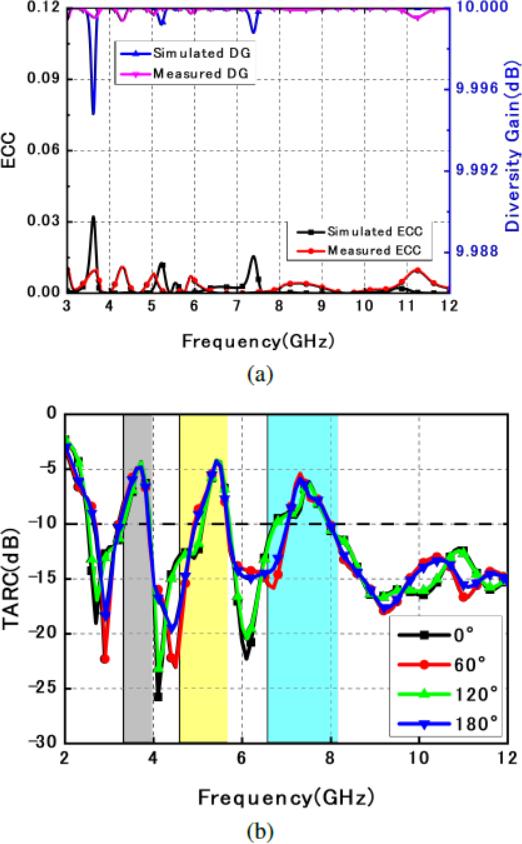
Figure 13: Simulated or measured results. (a)ECC and DG. (b) TARC.
C. Diversity Performance
The diversity characteristic is mainly determined by envelope correlation coefficient (ECC). ECC can effectively reflect the coupling degree between radiation patterns of different elements of the MIMO antenna. According to [12], a formula for ECC based on the S-parameter can be found in equation (3).
| (3) |
The ECC is shown in Fig. 13 (a), which meets the requirement of port isolation for UWB MIMO antenna.
A closely related parameter to ECC is the diversity gain (DG). It is also a vital parameter. The formula is as follows:
| (4) |
Figure 13 (a) depicts that the presented MIMO antenna has a great DG characteristic, which is greater than 9.99.
To predict the behavior of MIMO antenna systems, the total active reflection coefficient (TARC) is introduced. The simulated TARC is shown at Fig. 13 (b). The formula is expressed as:
| (5) |
D. Gain
Figure 14 indicates the gains of the MIMO antenna. The gain keeps stable from 2.5-12 GHz. Additionally, the gains at three rejected bands decrease dramatically.
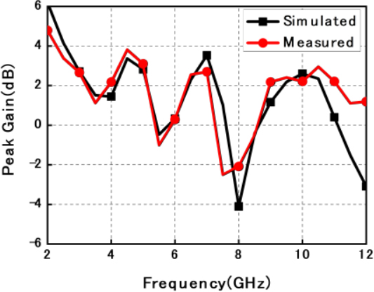
Figure 14: Simulated and measured gain of MIMOantenna.
Table 2: Performance comparison with previous antennas
| Paper | Electrical Size ( is Calculated at lower band) | Antenna Size | Band-width (GHz) | Mutual Coupling (dB) | The Detailed Bands Notched (GHz) | Bands Notched | DG | Feeder Method | |
| [5] | – | 0 | 9.97 | CPW feed | |||||
| [6] | - | 0 | 9.9 | CPW feed | |||||
| [7] | - | 0 | - | Microstrip feed | |||||
| [8] | 1 | - | Microstrip feed | ||||||
| [9] | 2 | – | - | Microstrip feed | |||||
| [10] | 2 | - | CPW feed | ||||||
| [11] | 2 | - | CPW feed | ||||||
| [12] | 3 | 9.99 | CPW feed | ||||||
| [23] | 3 | 9.95 | Microstrip feed | ||||||
| [26] | 4.52-4.6, 7.02-7.49, | 3 | 9.99 | Microstrip feed | |||||
| [27] | 3 | - | Microstrip feed | ||||||
| [28] | 3.72, 5.53 8.2 | 3 | - | Microstrip feed | |||||
| This paper | , | 3 | 9.99 | CPW feed |
E. Comparison
Table 2 compares performance between proposed antenna and previous ones. Although [5–7] are designed with MIMO technology, they cannot filter interference band. And the presented antenna has more notched bands compared with references [8–11]. In comparison to other similar antennas reported in references [12 ,23–28], the presented antenna has a better isolation, wider bandwidth, lower ECC level and CPW feed.
IV. CONCLUSION
Using a double Y-shaped decoupling structure, this paper introduces a CPW-fed UWB-MIMO antenna that exhibits triple notching characteristics and high isolation. Three notched bands of the antenna are realized by etching slots on the patch and coplanar ground. The proposed MIMO antenna has an ultra-wide band from 2.56-12 GHz with three notched bands which are from 3.31-3.96 GHz, 4.58-5.67 GHz and 6.57-8.16 GHz, and the measured isolation is all higher than 24 dB in whole bands. In addition, ECC are below 0.01 and DG is above 9.99. All the simulated and experiment results indicated that presented antenna is suitable in UWB field.
REFERENCES
[1] M. M. H. Mahfuz, M. R. Islam, M. H. Habaebi, N. Sakib, and A. K. M. Z. Hossain, “A notched UWB microstrip patch antenna for 5G lower and FSS bands,” Microwave and Optical Technology Letters, pp. 796-802, Apr. 2022.
[2] M. Koohestani, N. Azadi-Tinat, and A. K. Skrivervik, “Compact slit-loaded ACS-fed monopole antenna for Bluetooth and UWB systems with WLAN band-stop capability,” IEEE Access, pp. 7540-7550, Jan. 2023.
[3] D. Aissaoui, A. Chaabane, N. Boukli-Hacene, and T. A. Denidni, “Bandwidth enhancement of slot antenna using fractal shaped isosceles for UWB applications,” Applied Computational Electromagnetics Society (ACES) Journal, Feb. 2023.
[4] M. B. Tayel, T. G. Abouelnaga, and N. M. Badran, “Localization of breast tumor using four elements UWB wearable antenna,” Applied Computational Electromagnetics Society (ACES) Journal, vol. 37, no. 10, pp. 1021-1030, Mar. 2023.
[5] W. Yin, S. Chen, J. Chang, C. Li, and S. K. Khamas, “CPW fed compact UWB 4-element MIMO antenna with high isolation,” Sensors, vol. 21, no. 8, p. 2688, Apr. 2021.
[6] L. Zhang, Q. Feng, and M. K. Khan, “Design of a novel circularly polarized MIMO antenna with enhanced isolation for ultra-wideband communication,” Applied Computational Electromagnetics Society (ACES) Journal, Nov. 2022.
[7] L. Wang, Z. Du, H. Yang, R. Ma, Y. Zhao, X. Cui and X. Xi, “Compact UWB MIMO antenna with high isolation using fence-type decoupling structure,” IEEE Antennas and Wireless Propagation Letters, vol. 18, no. 8, pp. 1641-1645, Aug. 2019.
[8] G. Liu, Y. Liu, and S. Gong, “Compact uniplanar UWB MIMO antenna with band-notched characteristic,” Microwave and Optical Technology Letters, vol. 59, no. 9, pp. 2207-2212, Sep. 2017.
[9] B. R. Rao, K. S. Chakradhar, and D. Nataraj, “Design, optimization and experimental verification of UWB-MIMO antenna with WLAN and complete X-band notched characteristics, checked with characteristic mode analysis (CMA),” Analog Integrated Circuits and Signal Processing, Feb. 2023.
[10] F. Bahmanzadeh and F. Mohajeri, “Simulation and fabrication of a high-isolation very compact MIMO antenna for ultra-wide band applications with dual band-notched characteristics,” AEU - International Journal of Electronics and Communications, vol. 128, p. 153505, Jan. 2021.
[11] Q. Li, Y. Sun, and H. Fang, “Compact ACS-fed UWB MIMO antenna with dual band notches,” Applied Computational Electromagnetics Society (ACES) Journal, vol. 36, no. 1, pp. 55-60, Feb. 2021.
[12] J. Banerjee, A. Karmakar, R. Ghatak, and D. R. Poddar, “Compact CPW-fed UWB MIMO antenna with a novel modified Minkowski fractal defected ground structure (DGS) for high isolation and triple band-notch characteristic,” Journal of Electromagnetic Waves and Applications, vol. 31, no. 15, pp. 1550-1565, Oct. 2017.
[13] S. Jayant and G. Srivastava, “Close-packed Quad-element Triple-band-notched UWB MIMO antenna with upgrading capability,” in IEEE Transactions on Antennas and Propagation, vol. 71, no. 1, pp. 353-360, Jan. 2023.
[14] O. P. Kumar, P. Kumar, and T. Ali, “A compact dual-band notched UWB antenna for wireless applications,” Micromachines, vol. 13, no. 1, p. 12, Dec. 2021.
[15] X. Li, Y. Li, J. T. Huang and O. Yang Du, “A cross-slot loaded miniaturized UWB Vivaldi dual-polarized antenna,” 2021 International Conference on Microwave and Millimeter Wave Technology (ICMMT), Nanjing, China, pp. 1-3, May 2021.
[16] P. Kumari, R. K. Gangwar, and R. K. Chaudhary, “An aperture-coupled stepped dielectric resonator UWB MIMO antenna with AMC,” IEEE Antennas and Wireless Propagation Letters, vol. 21, no. 10, pp. 2040-2044, Oct. 2022.
[17] H. Li and N. Gong, “An SRR and CSRR based UWB-MIMO antenna,” 2020 IEEE International Symposium on Antennas and Propagation and North American Radio Science Meeting, Montreal, QC, Canada, pp. 679-680, July 2020.
[18] Z. Yang, F. Li, and F. Li, “A compact slot MIMO antenna with band-notched characteristic for UWB application,” 2018 International Conference on Microwave and Millimeter Wave Technology (ICMMT), Chengdu, May 2018.
[19] Z. Li, C. Yin, and X. Zhu, “Compact UWB MIMO Vivaldi antenna with dual band-notched characteristics,” IEEE Access, vol. 7, pp. 38696-38701, Jan. 2019.
[20] Z. He, Z. Yang, and J. Lv, “Design of a novel band-notched antenna for UWB MIMO communication system,” 2018 International Conference on Microwave and Millimeter Wave Technology (ICMMT), Chengdu, May 2018.
[21] A. K. Gautam, S. Yadav, and K. Rambabu, “Design of ultra-compact UWB antenna with band-notched characteristics for MIMO applications,” IET Microwaves, Antennas & Propagation, vol. 12, no. 12, pp. 1895-1900, Oct. 2018.
[22] Z. Tang, X. Wu, J. Zhan, S. Hu, Z. Xi, and Y. Liu, “Compact UWB-MIMO antenna with high isolation and triple band-notched characteristics,” IEEE Access, vol. 7, pp. 19856-19865, Jan. 2019.
[23] E. Thakur, N. Jaglan, and S. D. Gupta, “Design of compact triple band-notched UWB MIMO antenna with TVC-EBG structure,” Journal of Electromagnetic Waves and Applications, vol. 34, no. 11, pp. 1601-1615, July 2020.
[24] N. Jaglan, S. D. Gupta, B. K. Kanaujia, S. Srivastava, and E. Thakur, “Triple band notched DG-CEBG structure based UWB MIMO/Diversity antenna,” Progress in Electromagnetics Research C, vol. 80, pp. 21-37, Jan. 2018.
[25] Z. Tang, X. Wu, J. Zhan, S. Hu, Z. Xi, and Y. Liu, “Compact UWB-MIMO antenna with high isolation and triple band-notched characteristics,” IEEE Access, pp. 19856-19865, Jan. 2019.
[26] M. Agarwal, J. K. Dhanoa, and M. K. Khandelwal, “Ultrawide band two-port MIMO diversity antenna with triple notch bands, stable gain and suppressed mutual coupling,” AEU - International Journal of Electronics and Communications, vol. 120, p. 153225, June 2020.
[27] L. Wu, Y. Xia, and X. Cao, “A compact triple-band notched MIMO antenna for UWB systems,” Applied Computational Electromagnetics Society (ACES) Journal, Jan. 2018.
[28] S. Jayant and G. Srivastava, “Compact 4 4 proximity coupled microstrip fed UWB stepped slot MIMO antenna having triple band rejection,” Wireless Personal Communications, vol. 119, no. 4, pp. 3719-3734, Aug. 2021.
[29] S. Rahim, A. A. Elobied, W. Huang, and X. Yang, “Super-UWB MIMO antenna with dual band-notched and high gain,” Radio Science, vol. 57, no. 11, Nov. 2022.
[30] P. Jha, A. Kumar, A. De, and R. K. Jain, “Design of UWB antenna based on CSRR and EBG notch for prevention of undesired band,” 2021 8th International Conference on Signal Processing and Integrated Networks (SPIN), IEEE, pp. 982-986, 2021.
[31] L. Pei, C. Du, C. Shi, and H. Peng, “A gain enhanced low SAR dual-band MIMO antenna integrated with AMC for wearable ISM applications,” 2022 7th International Conference on Communication, Image and Signal Processing (CCISP), Chengdu, China, 2022.
BIOGRAPHIES

Chenzhu Du was born in Haikou, Hainan Province, China. She received the B.S. degree from the Xidian University, M.S. degree from Nanjing University of Posts and Telecommunications and PhD degree from Shanghai University, in 1995, 2003 and 2012, respectively, all in electromagnetic wave and microwave technology. She is currently an associate professor of Shanghai University of Electric Power. Her research interests include flexible antennas, multiband and wideband antennas, and MIMO technologies.

Huanchen Peng was born in Shanghai, China in 1999. He received the B.S. degree from the Shanghai University of Electric Power in 2021. He is currently pursuing the M.S degree in College of Electronics and Information Engineering, Shanghai University of Electric Power. His research interests include circular polarization antennas, flexible antennas, and multiband MIMO antennas.
ACES JOURNAL, Vol. 38, No. 11, 903–913
doi: 10.13052/2023.ACES.J.381109
© 2023 River Publishers