A Passive Adaptive Metamaterial Radome based on PIN Diodes
Ting-Ting Ge, Ming-Shun Li, Wei Song, Kai-Jiang Xu, Ke-Xin Xing, and Xin-Qing Sheng
1Beijing Institute of Technology, Beijing, China
2Aerospace Information Research Institute, Chinese Academy of Sciences
wsong@bit.edu.cn
Submitted On: June 5, 2023; Accepted On: December 11, 2023
ABSTRACT
Automatic protection of EM detecting systems from unexpected high-power incidence is important to the robustness and life of a passive detecting system. In this paper, an adaptive metamaterial radome which automatically shields the receiving antenna from strong incident wave is designed. Based on standard wire medium, PIN diodes are added between adjacent wires. When the incident EM wave is weak, the diodes are in “off” state and affect little to the transmission of the wire medium. When the incident EM wave is strong enough to turn the diodes to “on” state, electric currents will be automatically formed in the diodes and the power transmitted to the antenna will be largely reduced. The adaptive transmission of the proposed radome is validated by the simulation and measurement results.
Index Terms: Metamaterial, radome, tunable devices, wire media.
I. INTRODUCTION
Conventional radomes are used to provide physical protection for the antenna from its environment (wind, rain, sand, ice, etc.) [1], but new radomes also face the increasing technical requirements such as regulating electromagnetic (EM) beams. For example, EM metamaterials are introduced in radomes to provide functions such as improving the gain, changing the polarization of the antenna, and filtering the electromagnetic waves [2–5]. Metamaterials or metamaterials-inspired structures [6, 7] generally present frequency-selective properties. So metamaterials-incorporated devices can avoid out-of-band electromagnetic interference [8].
Wire medium is a classic type of metamaterial [9–14]. As shown in [15], a standard wire medium aligned in the z-axis with square lattice has anisotropic permittivity as
| (1) |
where
| (2) |
and are defined in [15].
In this medium, transmission line mode can be supported. When the length of the wire is properly designed, the wire medium reaches Fabry-Perot resonance and can provide high transmission for all angle incidence with subwavelength details in this canalization status [9, 10].
In metamaterial designs, active devices are utilized to provide flexibility for various applications [16–20]. Active metamaterials are also used in radomes to regulate the beams to enhance the angular stability [21] or to actively control the transmission [22–24]. However, for a detecting system, unexpected high-power incidence of EM waves is fatal and will affect the robustness of the detecting system. In this case, active metamaterials are not so effective in harnessing the EM waves because the state of the incidence is not known in advance.
In this paper, we propose an adaptive passive radome based on PIN diodes incorporated wire medium. This radome provides high transmission for low-power EM incidence. However, if the EM incidence is strong enough, the transmission will be dramatically reduced automatically. The mechanism of the radome is as follows. When working in a low-power incidence scenario, the PIN diodes are in “off” state and have little effect on the canalization working status of the wire medium. So high transmission is supported in the wire medium. When the incidence is so strong as to turn the PIN diodes to “on” state, forward currents will be formed between the PIN diodes, forming a shielding net in the wire medium, destroying the canalization status of the wire medium, and causing low transmission in the radome. Thus, adaptive transmission and automatic protection for the passive detecting system is realized from the hardware point of view, and it will significantly enhance the robustness and lifetime of a detecting system.
The operating mechanism is detailed below. The proposed radome was simulated by software CST Microwave Studio, with the diodes modeled by its equivalent circuits. Further, it was fabricated and measured, with its function verified by measurement results.
II. DESIGN OF THE RADOME
The proposed metamaterial radome consists of a standard wire medium. On a plane normal to the wires, a layer of PIN diodes is added connecting the neighboring wires. A thin dielectric layer is added to support the diodes, on which a metallic circuit is printed to connect the diodes to the wires, as shown in Fig. 1.
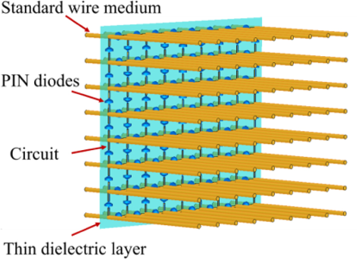
Figure 1: Structure of the proposed radome.
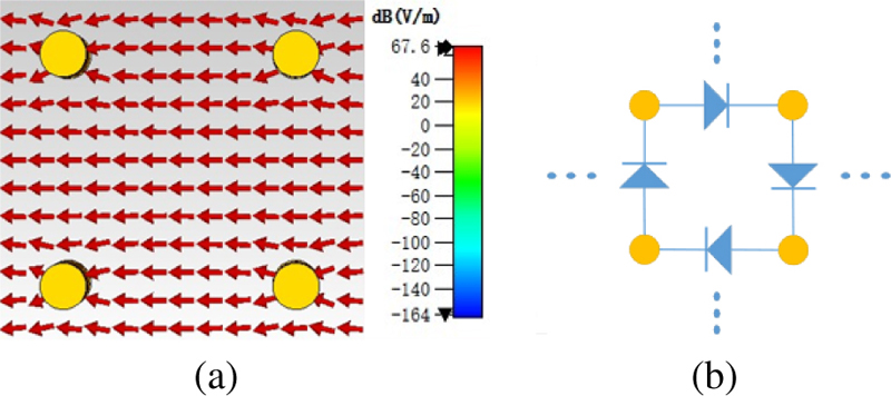
Figure 2: Scheme of PIN diodes integration in the wire medium: (a) CST result of electric field in a standard wire medium in the canalization status, (b) diode integration scheme.
The proposed radome is based on the transmission properties of the standard wire medium and the turn-on characteristics of the PIN diodes. The standard wire medium can be designed to work in the canalization status. That is, when the length of the metal wire is integer multiples of half-wavelength, the wire medium reaches Fabry-Perot resonance. Under such resonance, the wire medium experiences total wave transmission for all angles of the incident wave [7–8]. Since the lattice constant of the wire medium relates to the resolution of transmission, it should be designed sufficiently small to capture the detailed information of the transmitted EM wave.
Moreover, transmission line (TEM) mode is supported in the canalization status [7]. So, as shown in Fig. 2 (a), the transverse electric field between the metallic rods can provide a bias for the PIN diodes, providing us the chance to add semiconductors to dynamically adjust the transmission characteristics of the wire media.
Hence, a layer of PIN diodes is integrated, as illustrated in Fig. 2 (b). While the wire medium works in canalization status, when the incident power is not so strong as to turn the diodes on, the PIN diodes stay in “off” state and the diode array is equivalent to a layer of dielectric plane. In this case the canalization status of the wire medium will be largely preserved, leading to high transmission characteristics of the radome. When the incident power is so strong that the transverse electric fields between adjacent wires exceed the turn-on voltage of the diodes, the diodes will be turned on, and a forward current will be formed through the sheet.
Thus, an equivalent metallic net is generated on the diode layer, reflecting the incident electromagnetic waves automatically. With the canalization state of the wire medium destroyed by the forward currents, the radome shows low transmission.
III. SIMULATION ANALYSIS
A. The simulation models
The wire medium modeled consists of copper rods with diameter 2 mm and length 150 mm (2.5 wavelengths under 5 GHz). These rods form a array in a square lattice with lattice constant of 10 mm. Near one end (20 mm away from the end) of the wire medium, a thin F4B sheet with thickness 0.508 mm, and is used as the support medium for the diode array. On this sheet periodical holes are arranged for the metallic rods to go through. Between the holes, short metallic wires with width 0.3 mm are printed as a circuit to connect a PIN diode to its neighboring rods. The diode considered is the RF PIN diode BAR64-5 of Infineon Corporation. According to [25], the photo, the hardware basing circuit, and the equivalent circuit (EC) for the PIN diode (D1) used in the design is shown in Fig. 3. The operating frequency of the diode is 5 GHz, which is beyond the highest specified frequency by the manufacturer [25]. As the EC parameters for the design are not provided by the manufacturer, in this paper, the diode parameters were extracted from the measured S-parameters of the diode [26]. The extracted parameters are , and .
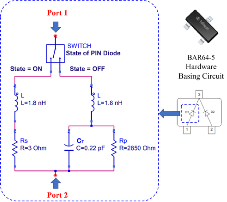
Figure 3: The photo, the hardware basing circuit, and the equivalent circuit of the PIN diode (D1) used in the design under “on” or “off” states.
Two horn antennas operating at 5 GHz are modeled as the transmitter and receiver, as shown in Fig. 4 (a). An observation plane is defined as a plane transverse to the wave transmission between the wire medium and the receiver. On this plane, the electric field is sampled to calculate the transmission of the radome.
Apart from the above model, unit cell models for diode “on” and “off” states are also used to study the proposed radome with sufficient periodicity. In the unit cell model, for the convenience of modelling, each PIN diode is separated into a pair of serially connected identical PIN diodes, as shown in Fig. 4 (c).
In both the finite structure model and unit cell model, a radome formed by the same standard wire medium without diodes and the F4B sheet is used as a reference.
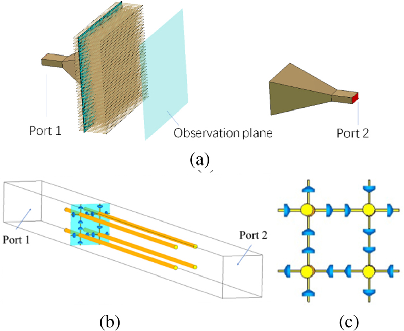
Figure 4: Illustration of the proposed radome: (a) The finite sized model, (b) the unit cell model, and (c) the cut plane where diodes are integrated.
B. Simulation results
With the finite model shown in Fig. 4 (a), the S parameters were calculated. Figure 5 shows that the difference in S21 between the proposed radome with Diodes “off” and the reference radome is generally less than 1 dB. It indicates the proposed radome only slightly degrades the transmission when the diodes stay off. When the diodes are turned on by strong incidence, the transmission gets obviously reduced. Compared with that of the reference, this difference reaches 6.6 dB at 5 GHz.
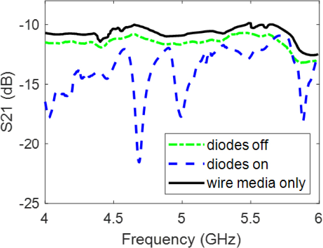
Figure 5: The transmission coefficients of the radomes.
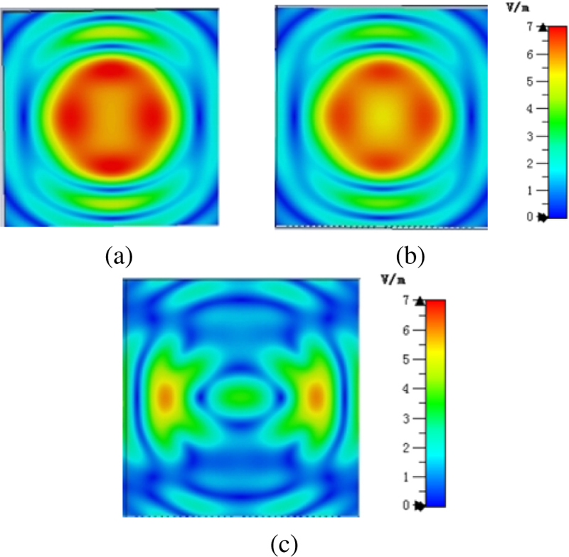
Figure 6: Simulated electric field distribution on the observation plan: (a) The reference radome, (b) radome with diodes “off,” and (c) radome with diodes “on.”
The amplitudes of electric field on the observation plane in the near field are compared in Fig. 6. It can be seen that the field distribution of the radome with diodes “off” is similar to that from a horn antenna with a reference radome. That is because in “off” state, known from the EC model, the impedance of the diode is very high, leading to small leakage currents between the metallic wires. So, compared to that in the case of standard wire medium, the leakage currents have little effect on the transverse field between the metallic wires. Consequently, the canalization status of wire medium is largely preserved. However, with diodes “on,” the impedance of the diode is small and the leakage currents between the metallic wires are large. The large leakage currents form a current net in the diode plane, dramatically reducing the transverse electric field on that plane. Without the supporting of the transverse electric field, the canalization status of the wire medium disappears, and the EM wave transmitted through the radome will be largely reduced. That is why we can find significantly weaker electric field on the observation plane, as shown in Fig. 6 (c), which demonstrates an obvious shielding effect of the radome.
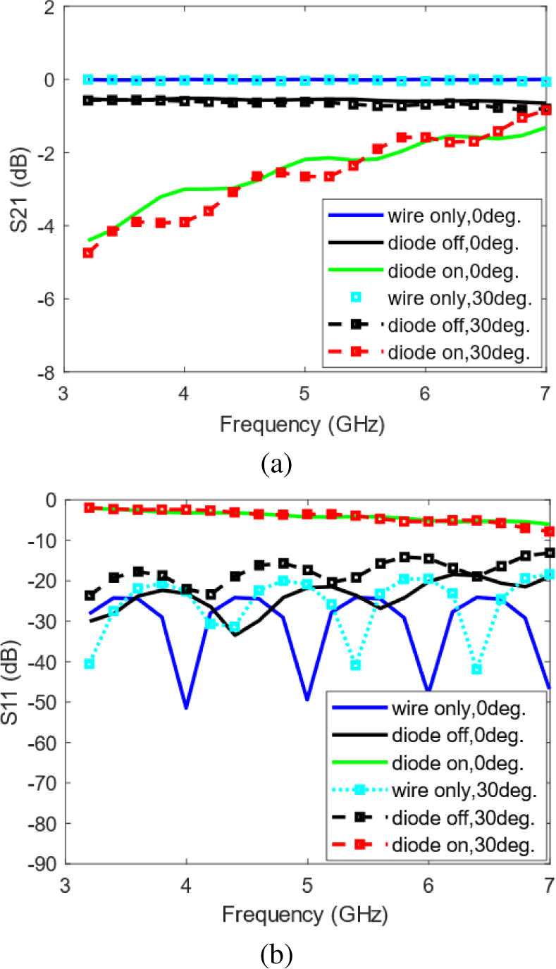
Figure 7: The transmission and reflection of the three radomes under unit-cell models with different incident angles: (a) S21 and (b) S11.
The reflection and transmission coefficients of the proposed radome are simulated with unit cell models. The incident angles of 0 and 30 degrees were investigated. As shown in Fig. 7, for the reference radome, the simulated transmission is 0 dB, both for the normal incidence case and the oblique incidence one. As for the radome with the diodes in “off” state, the S21 is around -0.6 dB for the normal or the oblique incidence cases, indicating that high transmission is supported, which is affected little by the incident angle. However, when the diodes are on, the proposed radome has highest reflection and lowest transmission for both cases. Specifically, the S11 results are about -3.5 dB at 5 GHz and the S21 results are low. While when the diodes are off, the reflection is around -20 dB, and the transmission is over -1 dB for either incidence.
IV. EXPERIMENTAL RESULTS
The proposed radome as investigated in Section III was fabricated by using copper rods, F4B and RF PIN diodes BAR64 of Infineon Corporation. In order to generate a strong incident electromagnetic wave to turn the diodes on, a power amplifier with output power of 39 dBm was used for feeding the antenna when the “on” state of the diode is required. Circulator and attenuators are utilized in the measurement system for protection measurement for high-power case. The near fields from the radome are scanned as shown in Fig. 8. The scan plane is 5 wavelengths (300 mm) away from the radome.
As shown in Fig. 9, the measured field distributions show similar trends to the simulation results. When the input signal is weak, which cannot turn on the diodes, the electric field on the observation plane has a similar distribution pattern to that without the radome. When the high-power amplifier is used, the incident electric field is so strong that the diodes are turned on, and the electric field, as shown in Fig. 9 (c), gets reduced by more than 3 dB on the observation plane compared with Fig. 9 (b). To some degree, the proposed radome reaches the goal to shield the receiver from strong electromagnetic wave.
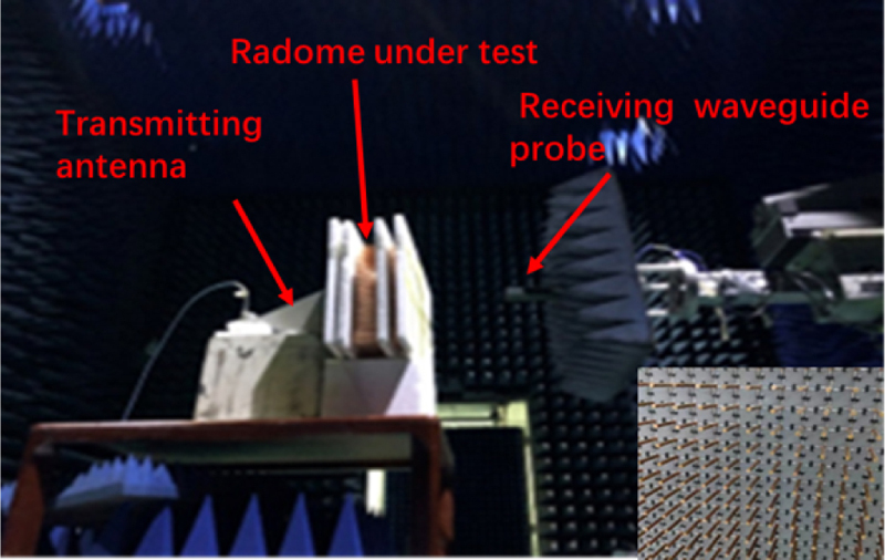
Figure 8: Measurement environment and the details of the fabricated radome (lower right-hand corner)
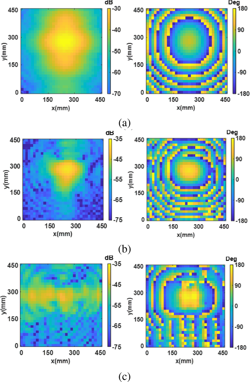
Figure 9: Near-field scanning results of field intensity and phase distribution: (a) Antenna without radome, (b) antenna with radome under low-power incidence, and (c) antenna with radome under high-power incidence.
Figure 9 also shows that the field amplitude in the case with the radome under low-power incidence is evidently smaller than that without the radome. The diode-integrated wire medium radome introduces larger losses in physical measurement than in simulation. The reasons are as follows:
1. The F4B board, the printed circuit, and the welding of the PIN diodes bring greater loss to the transmission channel in measurement than in simulation, which affected the transmission of the radome.
2. The manufacturing of the wire medium in the radome was not precise enough; e.g., some metallic rods were not sufficiently parallel.
3. The diode’s equivalent circuit model is based on circuit tests with voltage bias instead of EM wave scattering experiments. So, the equivalent circuit model is not sufficiently accurate when predicting its EM scattering effect.
The comparison between the proposed radome and other self-tuning radomes in the literature is made in Table 1.
Table 1: Comparison of self-tuning radomes (radome function: low power transmission, and high power absorption)
| Ref. | Structure | Freq.(GHz) | Verification | |
| Sim. | Meas. | |||
| [20] | Metasurface + PIN diodes | 2.5 | ||
| [21] | Metasurface + PIN diodes | 6.5 | ||
| This work | Metamaterial + PIN diodes | 5 | ||
V. CONCLUSIONS
In this paper, a passive metamaterial radome based on PIN diodes is proposed, to automatically shield the receiver from high-power EM incidence and protect the receiver system. The mechanism of the radome is explained. Simulation results show that the proposed radome shows obviously different transmission property under diodes “off” and “on” states. The reflection is around -20 dB with diodes “off,” while it is -3.5 dB with diodes “on.” Experimental results show that the transmission also gets reduced by more than 3 dB, when the receiver is illuminated by strong incidence with power of 39dBm, compared with the weak incident power case.
REFERENCES
[1] M. Latrach, H. Rmili, C. Sabatier, E. Seguenot, and S. Toutain, “Design of a new type of metamaterial radome for low frequencies,” Microwave and Optical Technology Letters, vol. 52, no. 5, pp. 1119-1123, 2010.
[2] G. V. Trentini, “Partially reflecting sheet arrays,” Ire Transactions on Antennas & Propagation, vol. 4, no. 4, pp. 666-671, 1956.
[3] A. P. Feresidis and J. C. Vardaxoglou, “High gain planar antenna using optimised partially reflective surfaces,” Microwaves Antennas & Propagation Iee Proceedings, vol. 148, no. 6, pp. 345-350, 2001.
[4] A. P. Feresidis, G. Goussetis, S. Wang, and J. C. Vardaxoglou, “Artificial magnetic conductor surfaces and their application to low-profile high-gain planar antennas,” IEEE Transactions on Antennas and Propagation, vol. 53, no. 1, pp. 209-215, 2005.
[5] Z.-J. Han, W. Song, and X.-Q. Sheng, “Broadband circularly polarized antenna by using polarization conversion metasurface,” Applied Computational Electromagnetics Society (ACES) Journal, vol. 35, no. 6, pp. 656-661, June 2020.
[6] P. Jha, A. Kumar, A. De, and R. K. Jain, “CPW-fed metamaterial inspired compact multiband antenna for LTE/5G/WLAN communication,” Frequenz, vol. 76, no. 7-8, pp. 401-407, 2022.
[7] P. Jha, A. Kumar, and N. Sharma, “A metamaterial inspired split ring resonator accomplished multiband antenna for 5G and other wireless applications,” Revue Roumaine des Sciences Techniques, Série Électrotechnique et Énergétique, vol. 68, no. 2, pp. 127-131, 2023.
[8] H. Zhou, S. Qu, B.-Q. Lin, J. Wang, H. Ma, Z. Xu, W. Peng, and P. Bai, “Filter-antenna consisting of conical FSS radome and monopole antenna,” IEEE Transactions on Antennas & Propagation, vol. 60, no. ISOCC, pp. 3040-3045, 2012.
[9] P. A. Belov and C. R. Simovski, “Canalization of subwavelength images by electromagnetic crystals,” PIERS Online, vol. 1, no. 1, pp. 37-41, 2005.
[10] P. A. Belov, Y. Hao, and S. Sudhakaran, “Sub-wavelength imaging by a slab of wire medium,” IEEE Antennas and Propagation Society International Symposium, pp. 4515-4518, 2006.
[11] P. A. Belov and M. G. Silveirinha, “Resolution of subwavelength transmission devices formed by a wire media,” Physical Review E, vol. 73, no. 2, pp. 645-666, 2006.
[12] X. Radu, A. Lapeyronnie, and C. Craeye, “Numerical and experimental analysis of a wire medium collimator for magnetic resonance imaging,” Electromagnetics, vol. 28, no. 7, pp. 531-543, 2008.
[13] S. Kosulnikov, D. Filonov, S. Glybovski, P. Belov, S. Tretyakov, and C. Simovski, “Wire-medium hyperlens for enhancing radiation from subwavelength dipole sources,” IEEE Transactions on Antennas & Propagation, vol. 63, no. 11, pp. 4848-4856, 2015.
[14] S. Kosulnikov, M. Mirmoosa, D. Vovchuk, S. Tretyakov, S. Glybovski, and C. Simovski, “Enhancement of radiation with irregular wire media,” IEEE Transactions on Antennas & Propagation, 2016.
[15] P. Belov, R. Marqués, S. Maslovski, I. Nefedov, M. Silveirinha, C. Simovski, and S. Tretyakov, “Strong spatial dispersion in wire media in the very large wavelength limit,” Physical Review B, vol. 67, no. 11, pp. 113103, 2003.
[16] J. P. Turpin, D. H. Werner, and D. E. Wolfe, “Design considerations for spatially reconfigurable metamaterials,” IEEE Transactions on Antennas and Propagation, vol. 63, no. 8, pp. 3513-3521, 2015.
[17] Y. Luo, K. Qin, H. Ke, B. Xu, S. Xu, and G. Yang, “An active metamaterial antenna with beam scanning manipulation based on a digitally-modulated array factor method,” IEEE Transactions on Antennas and Propagation, no. 99, pp. 1-1,2021.
[18] M. M. Shirkolaei and J. Ghalibafan, “Magnetically scannable slotted waveguide antenna based on the ferrite with gain enhancement,” Waves in Random and Complex Media, pp. 1-11, 2021.
[19] M. Shirkolaei and M. Aslinezhad, “Substrate integrated waveguide filter based on the magnetized ferrite with tunable capability,” Microwave and Optical Technology Letters, vol. 63, no. 4, pp. 1120-1125, 2021.
[20] M. M. Shirkolaei and J. Ghalibafan, “Unbalanced CRLH behavior of ferrite-loaded waveguide operated below cutoff frequency,” Waves in Random and Complex Media, vol. 32, no. 2, pp. 755-770, 2022.
[21] H. Bai, M.-B. Yan, W. Li, J. Wang, L. Zheng, H. Wang, and S. Qu, “Tunable frequency selective surface with angular stability,” IEEE Antennas and Wireless Propagation Letters, vol. 20, no. 6, pp. 1108-1112, 2021.
[22] Y. Zhao, J. Fu, Z. Liang, Z. Wang, Z. Zhang, B. Lv, and W. Chen, “Reconfigurable active frequency selective surface for ultra-wideband applications,” International Journal of RF and Microwave Computer-Aided Engineering, no. 5, pp. e22222, 2020.
[23] K. Wang, P. Liu, and H. Liu, “A miniaturized, low-profile, self-actuated radome for EM protection,” International Applied Computational Electromagnetics Society Symposium (ACES), Suzhou, China, pp. 1-2, 2017.
[24] Y. J. Zhou, H. X. Xu, Q. Y. Li, X. B. Wu, and S. Y. Xiao, “Active self-tuning metasurface radome for high-power microwave,” CIE International Conference on Radar (Radar), Haikou, Hainan, China, pp. 2719-2722, 2021.
[25] Data sheet of the RF PIN diode of Infineon Corporation with model of BAR64-5. https://www.infineon.com/dgdl/Infineon-BAR64-05-DS-v01_01-EN.pdf?fileId=5546d462689a790c01690f026ce63904.
[26] PIN SPAR data sheet of the RF PIN diode of Infineon Corporation. https://www.infineon.com/cms/cn/product/rf/rf-diode/rf-pin-diode/antenna-switch/bar64-05/#!?fileId=5546d46269e1c0190169ecdea94b46e8.
BIOGRAPHIES

Ting-Ting Ge received her B.E. degree from North China University of Technology, Beijing, China, in 2019, and her M.S. degree from the Beijing Institute of Technology. Beijing, China, in 2022. Her current research interests include EM property analysis, and metamaterial-based antenna design.

Ming-Shun Li received his B.E. degree in electronic information engineering from Dalian Maritime University in 2020 and the Master’s degree in electronic science and technology from Beijing Institute of Technology in 2023. His current research interests include wideband circularly polarized antenna design, low RCS antenna design, and electromagnetic metasurface design.

Wei Song received her Bachelor’s degree from North Eastern University, Shen-yang, China, in 2002, and her M.Sc. and Ph.D. degrees from Queen Mary, University of London, London, UK, in 2003 and 2008 respectively. She is currently an associate professor with the School of Integration Circuit and Electronics, Beijing Institute of Technology, Beijing, China. She has authored or co-authored over 40 papers in refereed journals and international conferences, and has co-authored a monograph in computational electromagnetics. Her current research interests include high-performance methods in computational electromagnetics, metamaterial EM property analysis, and metamaterial-based antenna design.

Kai-Jiang Xu received the B.E. degree from the School of Electronic Information Engineering, Anhui University, Hefei, China, in 2011, and the Ph.D. degree in the Center for Electromagnetic Simulation, School of Information and Electronics, Beijing Institute of Technology, Beijing, China, in 2018. He is currently a research assistant fellow with the Aerospace Information Research Institute, Chinese Academy of Sciences, Beijing. His current research interests include antenna design and applied computational electromagnetics.

Ke-Xin Xing received her B.E. degree from Hefei University of Technology, Hefei, China, in 2021, and she is currently pursuing the M.S. degree at the Institute of Radio Frequency Technology and Software from Beijing Institute of Technology. Her current research interests include EM property analysis and metamaterial-based antenna design.

Xin-Qing Sheng received his B.S., M.S. and Ph.D. degrees from the University of Science and Technology of China (USTC), Hefei, China, in 1991, 1994, and 1996, respectively. Sheng is a Chang-Jiang Professor of the School of Integration Circuit and Electronics at the Beijing Institute of Technology. Sheng has authored and co-authored over 150 papers in refereed journals, and three books: Essentials of Computational Electromagnetics (Singapore: IEEE Press-Wiley, 2012), A Brief Treatise on Computational Electromagnetics (Beijing: Science Press, 2004), and A Treatise on Electromagnetic Waves (Beijing: Science Press, 2007). Sheng authored SINOCOM, a simulation software for scattering by complex targets. His research interests include computational electromagnetics, scattering and antenna analysis, electromagnetic compatibility, and microwave imaging.
ACES JOURNAL, Vol. 38, No. 12, 922–928
doi: 10.13052/2023.ACES.J.381201
© 2023 River Publishers