Rigorous Analysis and Design of Resistor-Loaded Patch Antennas with Flexible Gain for Indoor Radar Sensors
Shu-Wei Yu, Xiao Zhang, Qiong-Sen Wu, Lei Zhu, Tao Yuan, and Xian-Qin Hu
1College of Information Engineering
Shenzhen University, Shenzhen, 518060, China
xiao.zhang@szu.edu.cn
*Corresponding Author
2School of Integrated Circuits
Guangdong University of Technology, Guangzhou, 510006, China
3Faculty of Science and Technology
University of Macau, Macao, 999078, China
4Avary Holding (Shenzhen) Co., Ltd
Shenzhen, 518060, China
Submitted On: June 18, 2023; Accepted On: October 22, 2023
ABSTRACT
A high-precision cavity model of resistor-loaded patch antenna (RLPA) with adjustable gain is proposed and rigorously studied in this article. In our analysis, the loaded resistors are perceived as controlled current sources, thus the RLPA can be solved as a modified cavity model. Accurate expressions of field distribution, input impedance, and radiation patterns are derived in this way, and a gratifying agreement has been achieved between the calculated and simulated results. Based on this approach, RLPAs for indoor motion radar are designed and analyzed. Comprehensive analysis is conducted to reveal the loading effect on radiation gain, radiation efficiency, and quality factor of RLPAs under various circumstances. Through altering the value of the loaded resistance, its radiation gain and coverage range can be flexibly adjusted. Besides, enhanced operating bandwidth and improved performance stability are also achieved due to the loaded resistors. Last but not least, several indoor motion radars based on the proposed patches are carried out and measured, which demonstrates the validity of the proposed method and design.
Keywords: Cavity model, flexible gain, indoor motion radar, resistor-loaded patch antennas.
I. INTRODUCTION
As the applications of smart home services are experiencing an appreciable growth in recent years, the microwave motion sensor system used for human body sensing has become an attractive solution for the realization of indoor intelligent services [1]. A microwave sensor is able to detect humans in a certain range [2], thus providing necessary data for the control strategy of smart home services.
Microstrip patch antennas are widely applied in these sensors, and they satisfy most requirements except the capacity of recognition scope adjustment, which is in high demand. The working scenario sample is illustrated in Fig. 1. Due to the penetrability of microwaves [3], humans in the occupied room are potentially detectable by the radar in the empty room. Consequently, the lights and air conditioner in the empty room will be falsely triggered. In the need of resolving this problem, a gain adjustable antenna is required for the purpose of flexible radiation coverage.
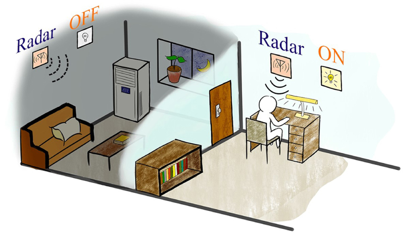
Figure 1: A scenario of the indoor motion sensor application. The 5.8 GHz radar in the occupied room detects the existence of humans and automatically turns the light on, while the radar in the empty room detects no living creature and turns the domestic appliances off.
Altering the transmitting power of the chip might be the most direct solution. However, most low-price chips cannot afford additional power-control circuits [4]. A relatively simple solution is to load a chip capacitor to the feeding circuit, which changes the reflection and thus adjusts realized gain.
To achieve a similar effect, lumped impedance can be loaded to the patches as well. Through loading capacitors or inductors to the patches, miniaturization [5–9], frequency/polarization tuning [10–17], or gain enhancement [18] can be achieved. However, the aforementioned antennas suffer from narrow bandwidth and are sensitive to manufacture deviation.
Compared with the sufficient studies above, relatively little research has concentrated on the topic of resistor-loaded patch antennas (RLPAs). In reported works, the resistor loading technique is primarily adopted for impedance matching [20], frequency tuning [21], and bandwidth widening [22–25]. These works have already noticed the non-negligible impact brought by resistors on the total efficiency. However, few of them propose precise models or analytical methods for RLPAs.
As is well known, the cavity model theory is an effective and high-accuracy method to analyze regular patch antennas [26–27]. However, to the best of our knowledge, no one used to apply the cavity model to the analysis of RLPAs.
In this article, a reformative cavity model for the rectangular patch antenna loaded with resistors is presented, which offers an alternative perspective on the analysis of this kind of patch antenna. This model perceives the loaded resistors as multiple controlled current sources, thus transferring the RLPA model into a multi-excitation cavity model. For validation, the calculation results with the proposed method are compared with the simulation results of the commercial ANSYS HFSS simulator, and satisfactory agreement is achieved.
Last but not least, an indoor radar module equipped with the proposed RLPA is designed and measured. By changing the loaded resistance, different coverage ranges are achieved. Additionally, the enhanced bandwidth can alleviate the risk of performance deviation of final products, which validates the promising practicality of RLPA.
II. ANALYSIS OF CAVITY MODEL
In this section, an improved cavity model is developed for the rectangular RLPA, which aims to provide a rigorous and accurate solution for the antenna design. The configuration of the antenna is shown in Fig. 2 (a). The patch is placed on the x-y plane, and four resistors are symmetrically loaded to the four corners of the patch for load-balance. The patch is fed by a probe along the central line.
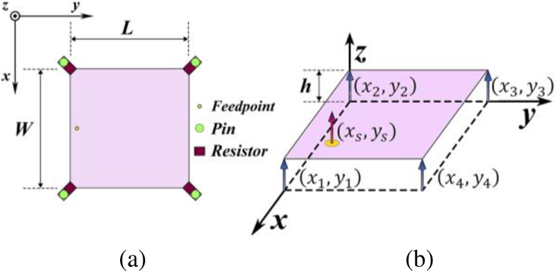
Figure 2: The proposed resistor-loaded patch antenna and its cavity model: (a) Configuration and (b) equivalent cavity model.
Table 1: Parameters of the resistor-loaded patch
| Param. | Val. (mm) | Param. | Val. (mm) |
| W | 11.8 | (x, y) | (11.8, 0) |
| L | 11.8 | (x, y) | (0, 0) |
| h | 0.8 | (x, y) | (0, 11.8) |
| (x, y) | (5.9, 0.5) | (x, y) | (11.8, 11.8) |
A. Electric field distribution
The electric field expression is critical for predicting the impedance and radiation patterns of the patch antenna, and so it is derived first. According to the classical cavity model [28], the rectangular patch antenna is perceived as a lossy cavity in which the electric field distribution is bounded by two parallel electric walls (at the top and bottom) and four magnetic walls surrounding the periphery of patch, as shown in Fig. 2 (b). Its interior field wave equation is written as
| (1) |
where k is the wave number in the dielectric and J is the total excitation source inside the cavity.
In the cavity model, the excitation is frequently equivalent to a current sheet which has width d and is located at (x, y) with a joint current of I. In order to solve the resistor loading problem, a resistor Z loaded to the patch is regarded as an E-controlled current source, which is equivalent to a current sheet with width d and located at (x, y) with a joint current of E(x, y)h/Z, as shown in Fig. 2 (b). Therefore, the total excitation J is expressed as
| (2) |
where the variable i represents the number of resistors loaded on the patch and the total amount of loaded resistors is set as q.
On the basis of this assumption, the loaded resistors do not change the eigen wave equation of this cavity. Utilizing the eigenmode expansion method, the solution of (1) can be expressed as the superposition of various eigenmodes of the cavity.
| (3) | |||
| (4) |
As shown above, the eigenfunctions are completely determined by the boundary condition of the cavity, and they are independent of the loaded resistors themselves.
Separately, the mode weighting coefficients A are determined by the total excitation J in the cavity.
| (5) |
The numerator and denominator of (5) are calculated by
| (6-a) |
| (6-b) |
where
| (7) |
Substituting (4), (5), (6-a), and (6-b) into (3) gives
| (8) |
in which
| (9) |
Since the dimensions of the excitations in this cavity model satisfy d W and d W (i = 1, 2, 3…), the expression of (8) is simplified as
| (10) |
It is worth mentioning that both the general solution and the specific solutions of E in (10) still remain unknown at this stage, so it is necessary to construct a set of homogeneous equations to solve E.
By substituting (x, y), (x, y), …, (x, y)into (10), respectively, a set of equations are thus established as
| (11) |
which is able to be written more concisely as a matrix equation below.
| (12-a) |
| (12-b) |
| (12-c) |
As shown in (9), a(x,y) is expressed as the sum of infinite series, and the orders m and n in the series represent the operating modes excited in the cavity. Since the computational script solely supports the summation of finite series, the maximum order of calculated modes should be limited. Considering the fact that the modes excited within a rectangular patch are generally dominated by a single dominant mode (such as the TM mode), the influence of higher-order modes is quite limited, which merely contributes to a small quantity of the imaginary part of the input impedance. Consequently, a finite-order model with m 5 and n 5 is adopted in this work, which is sufficient to provide satisfactory accuracy. Thus, every element of matrixes A and c can be calculated.
On condition that the qq matrix A is full rank, the field distribution vector b can be solved in a breeze. As a result, the E-field value at arbitrary points within the cavity is obtained from expression (10).
In addition, it is also worth mentioning that the W and L sizes are slightly larger than the physical sizes and of the patch because of the fringing-field effect [28].
| (13) |
B. Input impedance and radiation parameters
To obtain accurate input impedance and radiation efficiency of the patch antenna, its radiation and other loss should be included in the cavity model. Therefore, a wave number k in the dielectric is introduced.
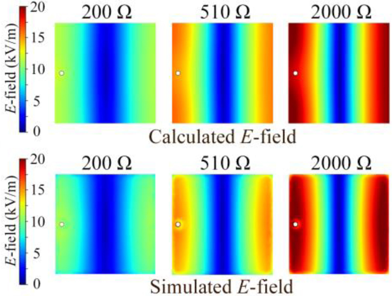
Figure 3: Calculated and simulated E-field magnitude distributions of resistor-loaded patch antenna loaded with 200 , 510 , and 2000 resistors. The feeding powers are fixed to 1 W.
| (14) |
The equivalent loss tangent derives from the radiation power, the conduction loss, the dielectric loss, and the surface-wave loss, which can be calculated by referring to the formulations in [28]. Because the resistor loss has already been included in the cavity functions, there is no need to calculate it separately.
Replacing each wave number k in the abovementioned equations with k, the matrix equation (12-a) needs to be solved once more, since the E-field distribution gets changed. Then the input impedance at the feed point is acquired by
| (15) |
Since the E-field distribution at the periphery has been acquired, the far fields are able to be calculated by the magnetic current model, in which the edges of the cavity are perceived as equivalent magnetic current sources [28].
III. CALCULATION AND SIMULATION
A. E-field distribution and input impedance
For reasons of observing the influence of resistor loading on input impedance, chip resistors of 200, 510, and 2000 are respectively loaded. The E-field distribution of RLPA is calculated through the proposed cavity model. The calculated and simulated E-fields are depicted in Fig. 3, and they are coincident with the cosine distribution of TM mode. In particular, by reducing the loaded resistance, the overall magnitude is attenuated. This indicates that smaller resistance will result in more consumed power at load.
With the derived E-field distribution, the input impedance can be calculated. Figure 4 illustrates the comparison results, which show excellent agreement with each other.
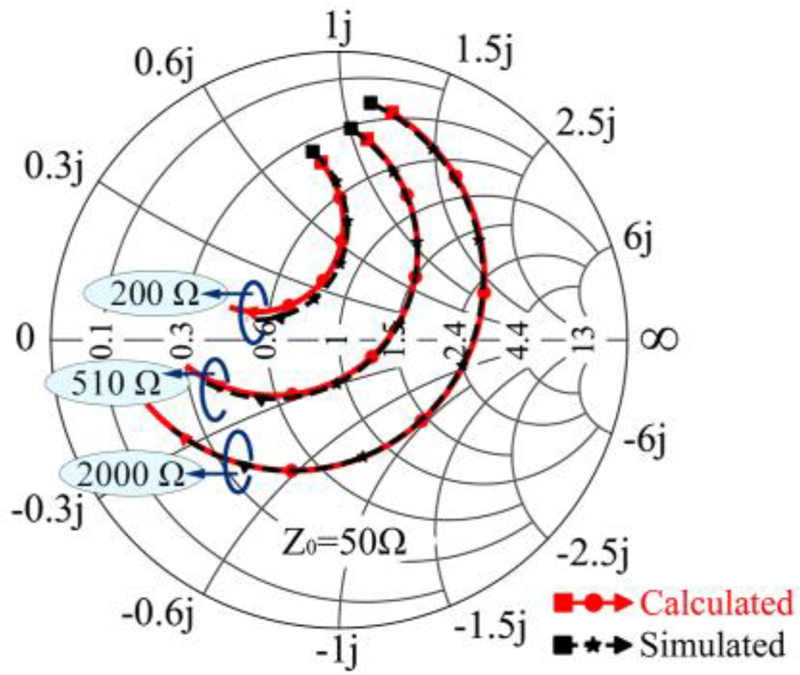
Figure 4: Calculated and simulated input impedances in the Smith Chart under different loaded resistance within frequency range of 5.3 to 6.3 GHz.
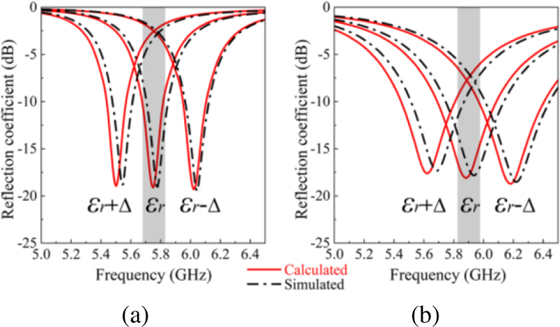
Figure 5: Calculated and simulated reflection coefficients of the resistor-loaded patch antenna under different relative dielectric permittivity ( = 4.4, = 0.4): (a) Patch antenna without resistors and (b) patch antenna with 510 resistors loaded.
Inexpensive commercial substrates, such as FR4, usually suffer from unstable permittivity, which may be harmful to the homogeneity of products in mass production. Fortunately, the enhanced bandwidth brought by resistor loading can well address this issue. Supposing the relative permittivity of FR4 has a deviation of = 0.4, the reflection coefficients |S| with and without resistor loading are carried out with calculation and simulation, and they are compared in Fig. 5. It can be seen in Fig. 5 (a) that the fluctuation has largely shifted the resonant frequency, and maximum |S| without resistors consequently increases to -1.8 dB in the band, which is almost total reflection. In contrast, as shown in Fig. 5 (b), the |S| of RLPA remains comparatively steady, and the maximum value is kept below -6 dB, which will not cause significant gain variation. As a result, even if a cheap substrate with unstable is employed, RLPA can still maintain steady performance.
B. Radiation gain and efficiency
The absorption of resistors will also affect the radiation gain and radiation efficiency of RLPA. The gain patterns under 200, 510, and 2000 resistance loadings are calculated and simulated in Fig. 6. The maximum gain of RLPA gradually diminishes from 0.75 to -4.6 dBi, when the resistance reduces from 2000 to 200 . The half-power beamwidth (HPBW) is kept constant. This is well coincident with the field distribution in Fig. 3. The power dissipation from radiating edges to loaded resistors primarily contributes to this phenomenon. Besides, the calculated gains are slightly lower than the simulated ones. This phenomenon derives from the delicate difference between calculated and simulated E-field distribution. As is shown in Fig. 3, the E-field magnitude at the corner in the simulation is slightly lower than the one in the calculation result, which results in reduction of power consumption caused by loaded resistors.
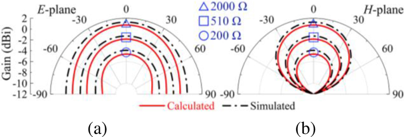
Figure 6: Calculated and simulated gain patterns at 5.8 GHz of the infinite-ground model under different loaded resistance: (a) E-plane patterns and (b) H-plane patterns.
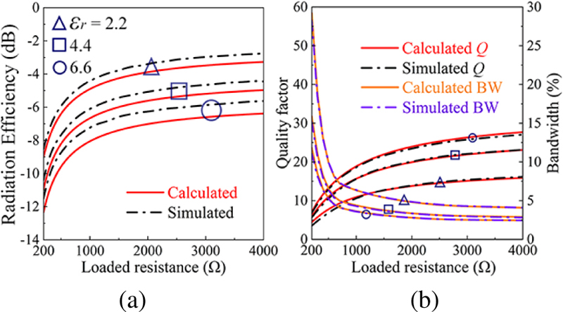
Figure 7: Calculated and simulated results of (a) radiation efficiency and (b) quality factor and bandwidth for 10-dB return loss. The substrate thickness is 0.8 mm.
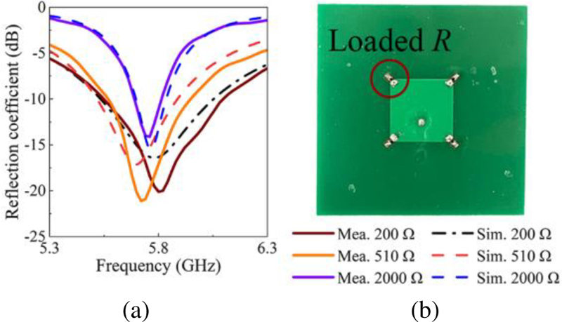
Figure 8: (a) Simulated and measured reflection coefficient of the fabricated patch antennas; (b) photograph of the fabricated prototype.
Further, R-Efficiency curves under different permittivity are calculated and plotted in Fig. 7 (a). There is an overall tendency that the radiation efficiency decreases as the loaded R declines. The efficiency curve alters drastically when loaded R is small, whereas it becomes more insensitive when loaded R gets larger. Additionally, as varies from 2.2 to 6.6, the overall radiation efficiency decreases, which evidently demonstrates that the increased substrate is adverse for antenna radiation.
The curves of derived quality factor Q and bandwidth (BW) are concentrated as well in Fig. 7 (b). The Q factor remains relatively low when 200 resistors are loaded, while it significantly rises as larger resistance is adopted. As a result of this increment, BW is narrowed down, which validates the inverse relationship between Q and BW. Further, when increases from 2.2 to 6.6, the Q factor gradually gets higher, while BW gets even narrower in the meantime. These results will serve as a constructive guideline for the design of RLPAs according to the requirements.
From the calculated and simulated results above, it is known that the radiation efficiency becomes relatively lower when smaller resistors are loaded to the patch. But in the case of indoor motion radar applications, the superiority of the resistor-loading technique far outweighs its drawback. In practical situations, the recognition scope varies from 0.1 m to 10 m, thus a high agility of efficiency adjustment is required. The resistor-loading technique brings noteworthy design flexibility and extra bandwidth, which contribute to a better adaptability to the diverse application requirements.
IV. MEASUREMENTS AND APPLICATIONS
The prototypes of the proposed RLPA with varied resistance are fabricated and measured. The photograph is shown in Fig. 8 (b). The measurements are conducted with Rohde & Schwarz ZVA vector network analyzer and a SY-16M near-field chamber.
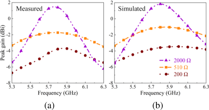
Figure 9: Peak gain of the antenna prototypes in the frequency range of 5.3 to 6.3 GHz: (a) Measured results and (b) simulated results.
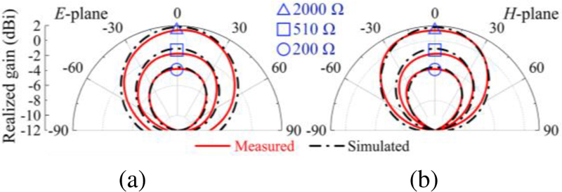
Figure 10: The radiation patterns of the antenna prototypes at 5.8 GHz: (a) E-plane and (b) H-plane.
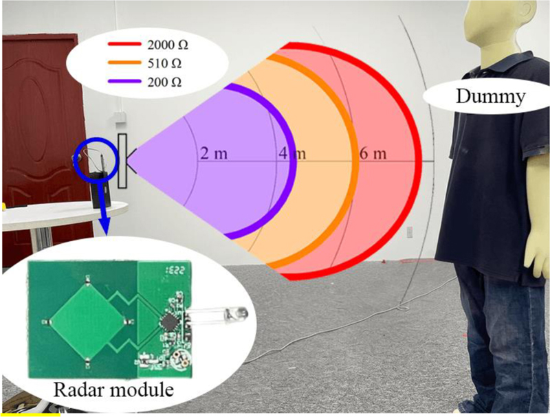
Figure 11: Photograph of the test site and the fabricated radar module. The measured recognition scopes of indoor motion radar modules loaded with 200-, 510-, and 2000- resistors are also illustrated. (The installation height is 0.9 m).
Figure 8 (a) illustrates the measured and simulated reflection coefficients of RLPAs loaded with resistors of 200, 510, and 2000 , while Fig. 9 illustrates the measured peak gain from 5.3 to 6.3 GHz. The simulated and measured results agree with each other. It is evident that both the impedance bandwidth and gain bandwidth are effectively enhanced. Figure 10 depicts the realized gain patterns of the prototypes in the E- and H-planes. The measured peak gains account for 2000, 510, and 200 resistance are 1.39, -1.73 and -3.78 dBi, respectively, and the HPBWs are kept unchanged.
An indoor motion radar module based on the proposed RLPA with flexible coverage area is developed, manufactured, and tested. The photograph of the radar module and the test facility is presented in Fig. 11. The transmitter and receiver are connected to two orthogonal feeds of the patch, which corresponds to two orthogonal polarizations. The radar module is horizontally installed with the wave beam directed at the dummy. The working principle is based on the Doppler effect of microwaves, and the detection distance is chiefly determined by the antenna gain, which is affected by loadedresistance.
The measured coverage range is also displayed. The recognition scopes of different radar modules range from 4.42 to 7.60 m, which could cover most of the domestic application demands of indoor motion radar. Our industrial partner has already put a series of microwave radar products with the proposed RLPA to the market, and a few gratifying application effects have been obtained from consumers.
V. CONCLUSION
In this article, a reformative cavity model of resistor-loaded patch antenna is proposed and comprehensively analyzed. The loaded resistors give rise to the reduction of Q factor, hence widen the bandwidth. The enhanced bandwidth provides better impedance-matching stability, which makes it possible that inexpensive material with unstable permittivity can be employed. The calculated results of the cavity model and the simulated results also present excellent agreement, which validates the precision of the proposed method. Further, in theory, the proposed cavity model is also applicable to other types of impedance loadings.
What is more, prototypes of RLPA with different gain levels are fabricated and measured, whose measured results solidly confirm the gain adjustment capacity. Besides, indoor motion radar modules employing the RLPA are manufactured and tested as well, and flexible coverage scope is achieved.
ACKNOWLEDGMENT
This work was supported in part by the Guangdong Provincial Department of Science and Technology, China, under Project No. 2020B1212030002, in part by the Shenzhen Science and Technology Innovation Commission, China, under Construction and Operation Project of Guangdong Provincial Key Laboratory and Guangdong-Hong Kong-Macau Joint Laboratory and Projects (No. JCYJ20190808115411853,No. CJGJZD-2022051714240411, and No. KQTD20180412181337-494), in part by the Postgraduate Education Branch of the China Education Society of Electronics, and in part by the Guangdong Provincial Department of Education, China, under the Innovation Team Project No. 2020KCXTD004.
REFERENCES
[1] D. Deiana, E. M. Suijker, R. J. Bolt, A. P. M. Maas, W. J. Vlothuizen, and A. S. Kossen, “Real time indoor presence detection with a novel radar on a chip,” Proc. Int. Radar Conf., Lille, France, pp. 1-4, Oct. 2014.
[2] B. Liu, M. Jian, Z. Lu, and R. Chen, “Indoor monitoring human movements using dual-receiver radar,” Proc. IEEE Radar Conf., pp. 0520-0523, May 2017.
[3] E. Nyfors, “Industrial microwave sensors—A review,” Subsurface Sens. Technol. Appl., vol. 1, no. 1, pp. 23-43, Jan. 2000.
[4] L. Jin, R. Cao, D. Li, and D. Wang, “Design of a new low-cost miniaturized 5.8 GHz microwave motion sensor,” Proc. IEEE Radar Conf., pp. 1-5, May 2021.
[5] H.-T. Chen, “Compact circular microstrip antenna with embedded chip resistor and capacitor,” Proc. IEEE Antennas Propag. Soc. Int. Symp., Dig., pp. 1356-1359, June 1998.
[6] P. Ferrari, N. Corrao, and D. Rauly, “Miniaturized circular patch antenna with capacitors loading,” Proc. IEEE MTT-S Int. Microw. and Optoelectron. Conf., pp. 86-89, Oct. 2007.
[7] G. Binoy, C. Aanandan, P. Mohanan, and K. Vasudevan, “Square microstrip slot antenna with chip capacitor loading for dual frequency operation,” Proc. IEEE Antennas Propag. Soc. Int. Symp., Dig., pp. 90-93, July 2001.
[8] K. M. Luk, R. Chair, and K. F. Lee, “Small rectangular patch antenna,” Electron. Lett., vol. 34, no. 25, pp. 2366-2367, Dec. 1998.
[9] M. Yang, Z. N. Chen, P. Y. Lau, X. Qing, and X. Yin, “Miniaturized patch antenna with grounded strips,” IEEE Trans. Antennas Propag., vol. 63, no. 2, pp. 843-848, Feb. 2015.
[10] M. C. Liang, Y. L. Kuo, Y. M. Yen, and W. C. Lai, “Capacitor-loaded frequency control scheme for circular patch antenna,” Electron. Lett., vol. 36, no. 21, pp. 1757-1758, Oct. 2002.
[11] M. Nishamol, V. Sarin, D. Tony, C. Aanandan, P. Mohanan, and K. Vasudevan, “Frequency and polarization tuning of a cross patch antenna using capacitive loading,” Proc. Int. Conf. Commun. Signal Process., pp. 92-96, Feb.2011.
[12] M. C. Laing, W. C. Lai, Y. M. Yen, and Y. L. Kuo, “A capacitor-loaded broadband circular patch antenna,” Proc. IEEE Antennas Propag. Soc. Int. Symp., Dig., pp. 302-304, July 2001.
[13] I. Rouissi, J. M. Floc’H, H. Rmili, H. Trabelsi, and A. Sharaiha, “Study of reconfigurable square patch antenna using capacitive loading,” Proc. Loughb. Antennas Propag. Conf., pp. 263-266, Nov. 2014.
[14] J. Li, B. He, L. Li, A. Zhang, J. Liu, and Q. H. Liu, “Capacitor-loaded circularly polarized annular-ring slotted microstrip patch antenna,” Proc. Int. Symp. Antennas, Propag. EM Theory, pp. 13-15, Oct. 2016.
[15] D. Schaubert, F. Farrar, A. Sindoris, and S. Hayes, “Microstrip antennas with frequency agility and polarization diversity,” IEEE Trans. Antennas Propag., vol. 29, no. 1, pp. 118-123, Jan. 1981.
[16] D. L. Sengupta, “Resonant frequency of a tunable rectangular patch antenna,” Electron. Lett., vol. 20, no. 15, pp. 614-615, 1984.
[17] S. S. Zhong and Y. T. Lo, “Single-element rectangular microstrip antenna for dual-frequency operation,” Electron. Lett., vol. 19, no. 8, pp. 298-300, Apr. 1983.
[18] X. Zhang and L. Zhu, “Gain-enhanced patch antennas with loading of shorting pins,” IEEE Trans. Antennas Propag., vol. 64, no. 8, pp. 3310-3318, May 2016.
[19] X. Zhang and L. Zhu, “Patch antennas with loading of a pair of shorting pins toward flexible impedance matching and low cross polarization,” IEEE Trans. Antennas Propag., vol. 64, no. 4, pp. 1226-1233, Apr. 2016.
[20] K.-L. Wong and Y.-F. Lin, “Microstrip-line-fed compact microstrip antenna with broadband operation,” Proc. IEEE Antennas Propag. Soc. Int. Symp., Dig., pp. 1120-1123, June 1998.
[21] A. Aoad, Z. Aydin, and E. Korkmaz, “Design of a tri band 5-fingers shaped microstrip patch antenna with an adjustable resistor,” Proc. IEEE Conf. Antenna Meas. Appl., pp. 1-4, Nov. 2014.
[22] J.-H. Lu and K.-P. Yang, “Slot-coupled compact triangular microstrip antenna with lumped load,” Proc. IEEE Antennas Propag. Soc. Int. Symp., Dig., pp. 916-919, June 1998.
[23] K.-L. Wong and Y.-F. Lin, “Small broadband rectangular microstrip antenna with chip-resistor loading,” Electron. Lett., vol. 33, no. 19, pp. 1593-1594, Sep. 1997.
[24] S. V. Hum, J. Chu, R. H. Johnston, and M. Okoniewski, “Improving the bandwidth of microstrip patch antennas using resistive loading,” Proc. IEEE Antennas Propag. Soc. Int. Symp., Dig., pp. 276-279, June 2003.
[25] J.-H. Lu, C.-L. Tang, and K.-L. Wong, “Slot-coupled compact broadband circular microstrip antenna with chip-resistor and chip-capacitor loadings,” Microwave Opt. Technol. Lett., vol. 18, no. 5, pp. 345-349, Dec. 1998.
[26] Y. Lo, D. Solomon, and W. Richards, “Theory and experiment on microstrip antennas,” IEEE Trans. Antennas Propag., vol. 27, no. 2, pp. 137-145, Mar. 1979.
[27] W. Richards, Yuen Lo, and D. Harrison, “An improved theory for microstrip antennas and applications,” IEEE Trans. Antennas Propag., vol. 29, no. 1, pp. 38-46, Jan. 1981.
[28] R. Garg, P. Bhartia, I. Bahl, and A. Ittipiboon, Microstrip Antenna Design Handbook, pp. 267-268, Norwood, MA, USA: Artech House, 2001.
BIOGRAPHIES

Shu-Wei Yu was born in Hangzhou, Zhejiang, China. He received the B.Eng. degree in electronic information engineering from Zhejiang University in 2016. Currently, he is a pursuing the M.Eng. degree in communication engineering in Shenzhen University. His research mainly focuses on impedance loaded patch antennas and circularly-polarized antennas.

Xiao Zhang was born in Gaozhou, Guangdong, China. He received the B.Eng. degree in information engineering and the M.Eng. degree in communication and information systems from the South China University of Technology, Guangzhou, China, in 2011 and 2014, respectively, and the Ph.D. degree in electrical and computer engineering from University of Macau, Macau, SAR, China, in 2017.
From September 2012 to August 2014, he was a research assistant with Comba Telecom Systems Limited, Guangzhou, China. From January 2018 to March 2018, he was a research fellow with the Antenna and Electromagnetic-Wave Laboratory in University of Macau, Macau, SAR, China. In 2018, he joined the College of Electronics and Information Engineering, Shenzhen University, Shenzhen, China, where he is currently an associate professor. His research interests include high-gain antennas, wideband antennas, circularly-polarized antennas, terminal antennas, filtering antennas, reflectarray, and characteristic mode analysis.
Dr. Zhang was the recipient of the Scientific and Technological R&D Award for Postgraduates of Macau in 2018. He was recognized as the Shenzhen Overseas High Caliber Personnel Level C in 2018. He was recognized as the Top 2% Scientists in 2019 and 2022 by Elsevier. He also serves as a reviewer for several journals, including the IEEE Transactions on Antennas and Propagation and the IEEE Antennas and Wireless Propagation Letters.

Qiong-Sen Wu received the B.Eng. degree in information engineering and the M.Eng. degree in electromagnetism and microwave engineering from South China University of Technology, Guangzhou, China, in 2011 and 2014, respectively, and the Ph.D. degree in electrical and computer engineering from the University of Macau, Macau, SAR, China, in 2018.
He joined the Antenna and Electromagnetic-Wave Laboratory in University of Macau, Macau, SAR, China, as a research fellow in May 2018. He is currently an associate professor with the School of Integrated Circuits, Guangdong University of Technology. His current research interests include microwave circuits and planar antennas with improved functionalities. He also serves as a reviewer for several journals, including the IEEE Transactions on Antennas and Propagation and the IEEE Transactions on Microwave Theory and Techniques.

Lei Zhu (Fellow, IEEE) received the B.Eng. and M.Eng. Degrees in radio engineering from the Nanjing Institute of Technology (now Southeast University), Nanjing, China, in 1985 and 1988, respectively, and the Ph.D. Degree in electronic engineering from the University of Electro-Communications, Tokyo, Japan, in 1993.
From 1993 to 1996, he was a Research Engineer with Matsushita-Kotobuki Electronics Industries Ltd., Tokyo, Japan. From 1996 to 2000, he was a Research Fellow with the École Polytechnique de Montréal, Montréal, QC, Canada. From 2000 to 2013, he was an Associate Professor with the School of Electrical and Electronic Engineering, Nanyang Technological University, Singapore. He joined the Faculty of Science and Technology, University of Macau, Macau, China, as a Full Professor in August 2013, was promoted as a Distinguished Professor in December 2016, and then as a Chair Professor in October 2023. From August 2014 to August 2017, he served as the Head of Department of Electrical and Computer Engineering, University of Macau. So far, he has authored or coauthored more than 810 papers in international journals and conference proceedings. His papers have been cited more than 16,600 times with the H-index of 63 (source: Scopus). His research interests include microwave circuits, antennas, periodic structures, transmitting/reflecting surfaces and computational electromagnetics.
Dr. Zhu was the Associate Editors for the IEEE TRANSACTIONS ON MICROWAVE THEORY AND TECHNIQUES (2010-2013) and IEEE MICROWAVE AND WIRELESS COMPONENTS LETTERS (2006-2012). He served as a General Chair of the 2008 IEEE MTT-S International Microwave Workshop Series on the Art of Miniaturizing RF and Microwave Passive Components, Chengdu, China, and a Technical Program Committee Co-Chair of the 2009 Asia–Pacific Microwave Conference, Singapore. He served as the member of IEEE MTT-S Fellow Evaluation Committee (2013-2015), and as the member of IEEE AP-S Fellows Committee (2015-2017). He was the recipient of the 1997 Asia–Pacific Microwave Prize Award, the 1996 Silver Award of Excellent Invention from Matsushita-Kotobuki Electronics Industries Ltd., the 1993 Achievement Award in Science and Technology (first prize) from the National Education Committee of China, the 2020 FST Research Excellence Award from the University of Macau, the 2020 and 2022 Macao Natural Science Awards (Second Prize) from the Science and Technology Development Fund (FDCT), Macau, and the 2024 IEEE MTT-S Microwave Application Award. He was elevated to the IEEE Fellow in November, 2011.

Tao Yuan received the B.E. degree in electronic engineering and the M.E. degree in signal and information processing at Xidian University, Xi’an, Shaanxi, China, in 1999 and 2003, respectively, and the Ph.D. degree in electrical and computer engineering at National University of Singapore, Singapore, in 2009.
He was a visiting scholar at University of Houston (2007–2008). He is now a distinguished professor (2016-till now) with the College of Electronics and Information Engineering at Shenzhen University, Shenzhen, Guangdong, China. He is the director of the Guangdong Provincial Mobile Terminal Microwave and Millimeter-Wave Antenna Engineering Research Center and the deputy director of the Guangdong-Hong Kong Joint Laboratory for Big Data Imaging and Communication. He is a visiting professor (2021-till now) at Chongqing University, China, and an adjunct professor (2021-till now) at Fudan University, China. He is leading a group of over 70 members performing fundamental and application studies in the areas of RF/microwave/millimeter-wave frontend devices, antennas, ICs, and advanced manufacturing techniques for microwaves and microelectronics. He has PIed/co-PIed over 20 governmental and entrepreneurial research projects on 5G MIMO antennas (arrays), transmission lines, and packaged antennas for smart IoT/mobile terminals. His current research interests include design and implementation of novel RF frontend chips/modules and integrated devices/antennas/circuits for 5G/6G applications. He has advised over 40 graduate students and has authored/co-authored over 150 international journal and conference publications. He is holding over 100 licensed CN patents. He has co-authored 2 books: Antenna Design for 5G Mobile Terminals (Posts & Telecom Press, 2021) and Practical Design and Development of FPGA—Based on Xilinx and Verilog HDL (Publishing House of Electronics Industry, 2023).
Dr. Yuan is a member of the IEEE Antennas and Propagation Society, IEEE Microwave Theory and Techniques Society, and the China Communications Standards Association. He is a senior member of the Chinese Institute of Electronics (CIE) and the China Institute of Communications (CIC). He serves as a reviewer for several international journals and conferences and serves as a Guest Editor for Coatings. He is the organizing committee member of APMC2020, Mar-For (2021, 2022) (TPC member), and CSRSWTC2021 (general chair). He serves as a consultant for several research institutions and ICT companies in China. He received numerous teaching, entrepreneurial, and talent awards in China. He is the recipient of the Outstanding Individual Award (2018), the Outstanding Graduate Student Advisor (2021), the Excellent Undergraduate Thesis Instructor (2022), and the Undergraduate Teaching Outstanding Contribution Award (2022) from Shenzhen University and the co-recipient of the CIC Science and Technology Second Place Award (2020) and the Excellent Teaching Management Team of Tencent Team Award (2022). His students and group members have received over 150 scholarships/awards in China and international conferences, including the CSRSWTC2021 Best Paper Award and the IEEE RWW2022 student paper competition finalist.

Xian-Qin Hu received the B.E. degree in chemical engineering and technology from Anhui University of Science and Technology in 2006. He has been engaging in the research and development of new technologies, new materials, new products, and new processes for printed circuit boards at Avary Holding (Shenzhen) Co., Ltd.
He is currently the research and development manager of the Avary Holding R&D Center (Shenzhen), and director of the Guangdong Flexible Printed Electronics Engineering Technology Research Center.
ACES JOURNAL, Vol. 38, No. 10, 807–816
doi: 10.13052/2023.ACES.J.381008
© 2023 River Publishers