A Low-profile Dual-band Dual-polarization Co-aperture Array Antenna with High Isolation
Liang-Xin Xia, Qi lei Zhou, Neng-Wu Liu*, and Guang Fu
1National Key Laboratory of Antennas and Microwave Technology
Xidian University, Xian, 710075, China
LiangxinXia@stu.xidian.edu.cn, 20021110068@stu.xidian.edu.cn,
nwliu@xidian.edu.cn, gfu@mail.xidian.edu.cn
Submitted On: June 19, 2023; Accepted On: November 12, 2023
ABSTRACT
This paper proposes a low-profile high-isolation dual-polarization array antenna operating in the L/S band. The radiating unit of the array antenna adopts U-shaped bending dipoles to realize the staggered arrangement of high- and low-band units, and is connected to the feeding network by a coaxial cable. To achieve the non-influence of high-band and low-band feed networks, multi-layer printing technology is used and grooves are etched on the metal plate. In order to reduce the coupling of the high- and low-band dipoles at low frequency, a bandpass filter is added to the high-band feed network, which greatly improves the isolation at low-frequency. The measured results show that the impedance bandwidth of the array is 4.5% (0.971-1.015 GHz) and 7.5% (1.89-2.04 GHz), with gains of 15 and 19 dBi at 1 GHz and 2 GHz, respectively. And the isolation between the dual-polarized ports more than 50 dB and 35 dB was achieved at 1 GHz and 2 GHz, respectively. The proposed array will have practical value in L/S band full-duplex wireless communication systems.
Keywords: dual-polarization, high-isolation, multi-layer network, U-shaped bending dipoles.
I. INTRODUCTION
In recent years, a variety of antenna technologies have been developed in the direction of easy integration, multi-band [1–2], multi-polarization [3–4] and low profile to meet the requirements of modern communication technology. Among them, the dual-polarization technology and the dual-band technology can not only increase the capacity of the communication system but also realize various radiation functions, such as transceiver integration [5–6]. The arrangement of multiple antenna units with different polarizations and bands in the same aperture greatly reduces the size of the antenna array.
Some multi-band and multi-polarization co-aperture array antennas have been proposed by researchers. Initially, a single antenna [7–10] or combination antenna [11–12] with dual-band and dual-polarization characteristics is used as an element to construct the array to improve the channel capacity of the array antenna. This antenna is usually connected to a broadband or dual-band feed network. However, it usually results in low aperture efficiency and low gain in the high-frequency band, and it cannot effectively use the array aperture. To improve the aperture efficiency at high frequency, the researchers have interspersed the high-band units in the low-band array to increase the number of units in the high-frequency arrays [13–16]. The authors in [16] propose a co-aperture antenna with L/S band placed in the same layer. To realize the dual-band co-aperture antenna, the L-band dipole is bent, and the S-band dipole is placed in the same layer in the empty part of the L-band dipole, taking advantage of the small physical size occupied by the bending dipole. Furthermore, different frequency antennas can also be placed on different layers [17–20]. In [20], to realize the dual-band antenna co-aperture placement in different layers, the antenna etches the weak electric field area in the middle of the upper C-band patch to make room for the normal radiation of the lower X-band patch antenna. In addition to modifying the low-frequency antenna to realize the displacement of the horizontal space and the vertical space, the dual-band co-aperture can be obtained by using the antenna with small lateral occupation area. For example, the author in [21] adopted Vivaldi and dipole antennas to realize the co-aperture placement of arrays with different frequencies of S/X, but the profile is higher.
In this paper, a multi-layer feeding network with filter is designed to solve the feeding problem of a dual-frequency dual-polarization array based on reference [16]. It is easy to fabricate by reasonably arranging the HB and LB feed networks, and it achieves high isolation between the two ports. Through simulation and measurement, it is found that the antenna achieves the impedance bandwidths of 4.5% and 7.5% and gains of 15 and 19 dBi at 1 GHz and 2 GHz, respectively. The isolation between the two ports reaches 35 dB.
II. ANTENNA DESIGN
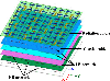
The overall configuration of the array antenna is shown in Fig. 1. The low-profile dual-band and dual-polarized co-aperture array antenna consists of a staggered arrangement of high-band and low-band dipoles and a multi-layer power divider network. The overall structure of the antenna is divided into antenna radiation layer, coaxial cable, low-band feed network, and high-band feed network from top to bottom.
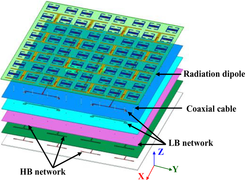
Figure 1: Configuration of the dual-band and dual-polarization array antenna.
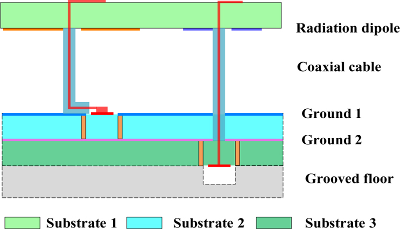
Figure 2: Schematic diagram of multilayer stacked structure.
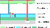
The hierarchical structure of the entire array antenna is shown in Fig. 2. The radiation layer of the antenna is printed on the bottom layer of FR4 with a thickness of 1 mm. The reasonable arrangement of the high- and low-band dipoles is realized by using the gap of the low-band bending dipole and the miniaturization of the high-band bending dipole, and they are connected to the high- and low-band feed network of the ground through the coaxial cable. The feed network is printed on a two-layer dielectric substrate F4B ( =2.1) with a thickness of 1 mm by using multi-layer dielectric printing technology. The low-frequency feed network adopts the transmission line form of CPW to realize a 1:16 power division network. The high-band feed network is located in the lower layer of the low-band feed network, and the stripline power division feed network is realized by etching slots on the metal ground. In addition, the high-band network is also cascaded with a bandpass filter to achieve high isolation between the two ports at low frequency.
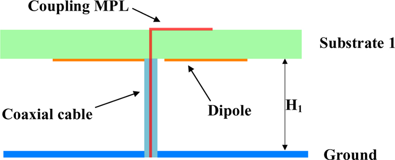
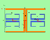
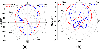
Figure 3: The configuration of a dual-band coaxial feed dipole (side view).
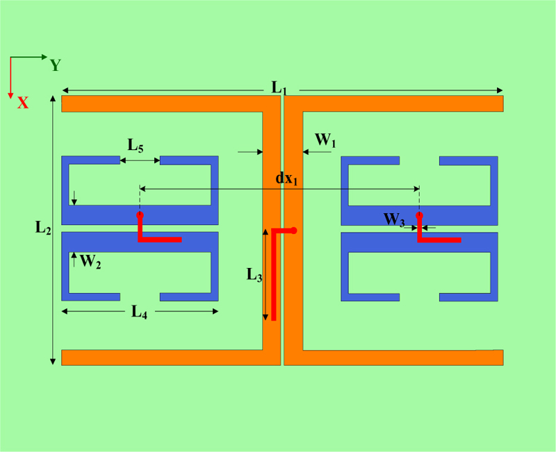
Figure 4: The configuration of the dual-polarized dipoles (top view).
A. Analysis of antenna unit
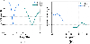
The array unit uses U-shaped bend dipoles. The feed structure and relative positions of the high- and low-band dipoles are shown in Fig. 3 and Fig. 4. The coupling microstrip line (MPL) is used to achieve a wider operating bandwidth, and the coaxial cable is used to connect the dipole unit to the feed network. To validate the antenna unit design, the dual-band array antenna unit is simulated. The simulated S-parameters and radiation patterns are shown in Figs. 5 and 6. Both work well, but the isolation of the two ports is slightly worse at low frequency.
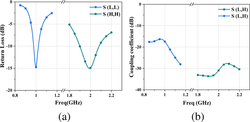
Figure 5: Simulated S-parameters of the dual-band element: (a) Return loss and (b) coupling coefficient between the dual-polarized ports.
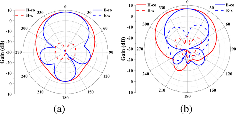
Figure 6: The radiation patterns of the dual-band element: (a) LB element @ 1 GHz and (b) HB element @ 2 GHz.
B. Analysis of dual-band network with filter
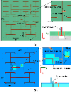
The array antenna usually prints the power division feed network on the dielectric substrate, but the high-band and low-band feed networks have the problem of overlapping or crossing transmission lines on the same layer. As shown in Fig. 7, a multi-layer feed network is proposed in this paper. The high-band and low-band feed network is realized by using two layers of dielectric substrates and a metal plate with etched grooves.
To avoid interference between the upper and lower layers, the high-band network is placed in the lower layer and is designed in the form of striplines, and the low-band network is placed on the upper layer using CPW. The two sides of the stripline and CPW realize the potential of the upper and lower ground through metal holes to balance and eliminate resonance, which is represented by a metal wall in Fig. 7. In addition, in order to solve the problem of strong coupling between high-band and low-band dipoles at low frequencies, the bandpass filter and the high-band feed network are cascaded to achieve high isolation between two ports. The low-band network is connected to an open branch at the main port to adjust the impedance of the low-band array to avoid frequency offset problems caused by manufacturing.
Based on the principle of T-type equal-amplitude power divider, a dual-band multi-layer feed network is designed. The key size parameters of the radiating dipoles and the feed network are shown in Table 1.
Table 1: Value of the parameter in the antenna array
| Parameter | Value (mm) | Parameter | Value (mm) |
| H | 28 | L3 | 24 |
| H2 | 1 | L4 | 43 |
| W1 | 11 | L5 | 11 |
| W2 | 12 | dx1 | 75 |
| W3 | 1.25 | dx2 | 68 |
| W4 | 550 | dx3 | 136 |
| W5 | 550 | dy1 | 68 |
| L1 | 131 | dy2 | 136 |
| L2 | 72 |
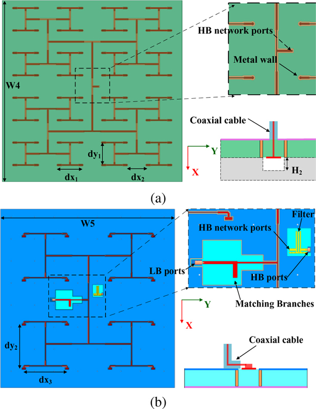
Figure 7: Schematic diagram of the HB and LB feed network based on T-shape power divider: (a) HB network and (b) LB network.
In order to verify the design of the multi-layer feed network, the high-band and low-band feed networks are simulated and verified. The S-parameters of the network are shown in Fig. 8. According to Fig. 8, the high-band and low-band feed networks achieve good impedance matching in their respective bands, and the bandpass filter also achieves blocking characteristics in the low frequency, finally achieving high isolation between the two ports.
By analyzing the dual-band radiating dipoles and feed network, the low-profile array antenna can achieve higher gain, better impedance matching, and isolation at 1 GHz and 2 GHz.
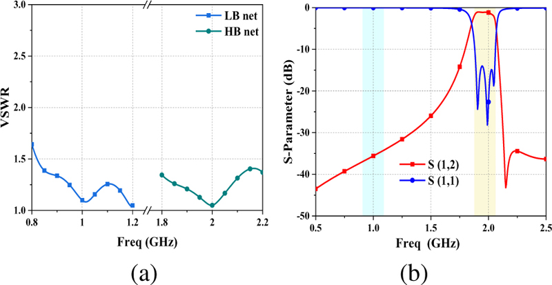
Figure 8: Simulated results of the feed network and filter: (a) VSWR of the HB and LB feed network and (b) S-parameters of the filter.
III. RESULTS AND EXPERIMENTAL VALIDATION
In order to verify the above design effectively, the array antenna is simulated and fabricated. The S-parameter of the antenna was measured using a vector network analyzer, and the radiation patterns of the antenna at 1 GHz and 2 GHz are measured in an anechoic chamber.
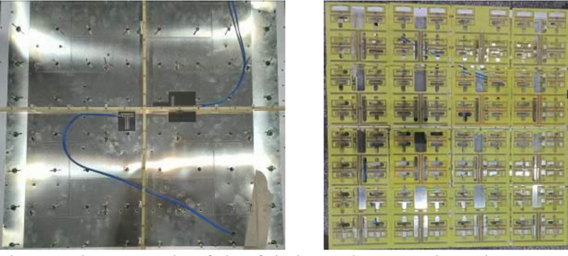
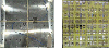
Figure 9: Photograph of the fabricated network and antenna.
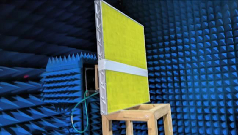
Figure 10: Photograph of measuring the fabricated antenna.
The photographs of the fabricated antenna and the measurement environment are shown in Figs. 9 and 10, respectively.
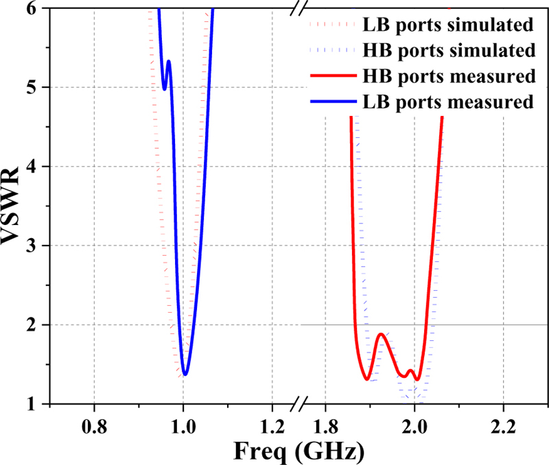
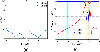
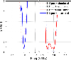
Figure 11: Simulation and measurement VSWR of the dual-band antenna.
Firstly, the voltage standing wave ratio (VSWR) of the proposed antenna is measured, and the results are shown in Fig. 11. The simulation results of the two bands are in good agreement with the measured results, but there is a slight deviation in the operating frequency. But the VSWR2 can still be satisfied at 1 GHz and 2 GHz. In addition, the results show that the impedance bandwidth of the antenna is 4% (0.971-1.015 GHz) and 7.5% (1.89-2.04 GHz), respectively, which is basically consistent with the simulation.
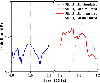
As shown in Fig. 12, the isolation between the dual-polarized ports is more than 50 dB and 35 dB at 1 GHz and 2 GHz, respectively. It shows that the filter has the effect of significantly improving the isolation.
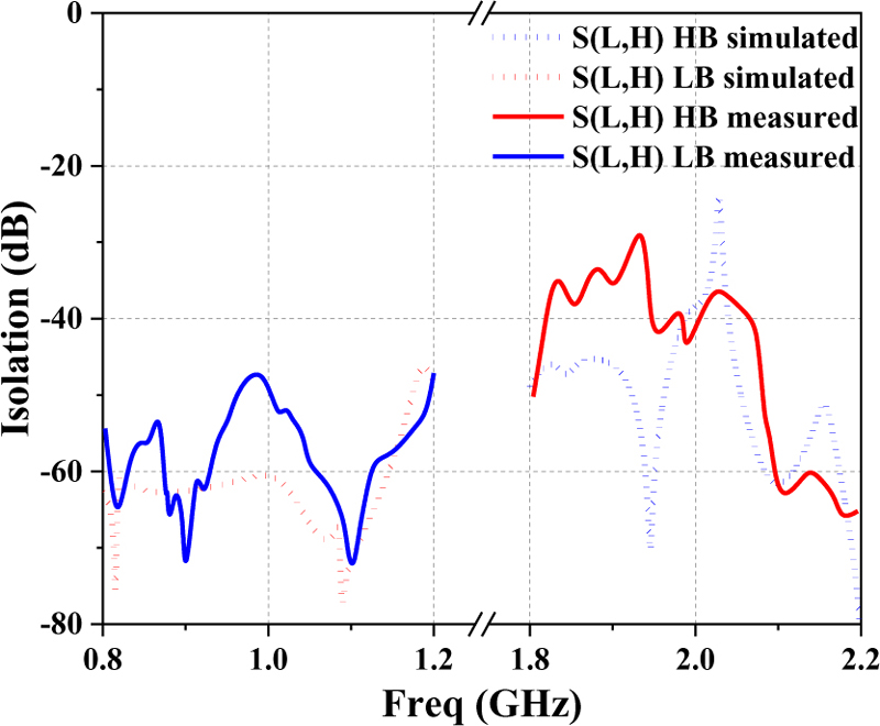
Figure 12: Simulation and measurement coupling coefficient of the dual-band antenna.
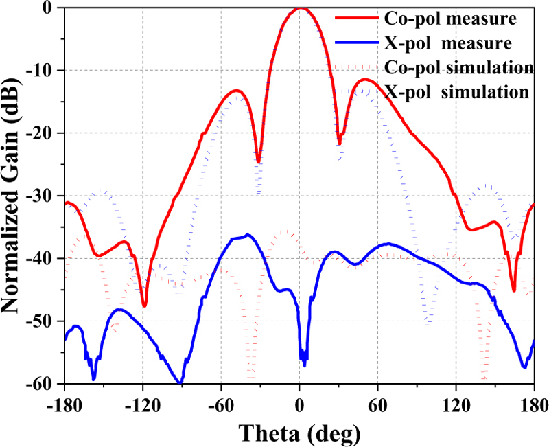
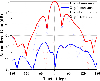
Figure 13: Simulated and measured pattern of the antenna array @ 1 GHz (yoz).
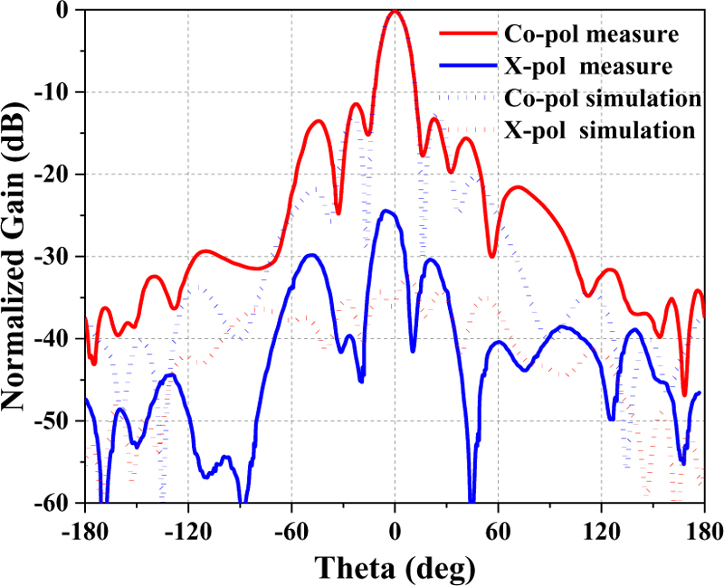
Figure 14: Simulated and measured pattern of the antenna array @ 2 GHz (yoz).
The radiation patterns of the proposed dual-band dual-polarized antenna are shown in Figs. 13 and 14. Among them, they are the radiation patterns of the yoz-plane when the high- and low-band arrays, respectively, are excited. It can be seen that the main beam of the antenna array at low frequency and high frequency is consistent with the simulation, but the measured side lobe level is slightly higher at -11.5 dB, and the measured gain is 15 dB and 19 dB, slightly lower than the simulation 15.5 dB and 19.6 dB. The cross-polarization of the array at high frequency is obviously different from the simulation results. This is mainly because the cross polarization level is high when the antenna unit deviates from the broadside direction, and the installation error causes the dipole plane to tilt slightly, so that the broadside direction of the antenna is not all pointing to 0, thus increasing the cross polarization level.
According to the actual measured gain, it is calculated that the aperture efficiency of the co-aperture array antenna at low frequency and high frequency is 85% and 54%, respectively. The low aperture efficiency of the high frequency is mainly due to the insertion loss of the filter and power division network.
IV. CONCLUSION
In this paper, a low-profile dual-band and dual-polarization co-aperture array antenna with a multi-layer feed network is proposed, in which the antenna elements are printed on the dielectric substrate in a staggered manner, and the feed network is fabricated using multi-layer printing technology to achieve high and low-band network without affecting each other. The array antenna can achieve different polarizations and better isolation at dual frequencies, can also obtain higher gain at the same time, and it has practical value.
ACKNOWLEDGMENT
This work is supported by the National Natural Science Foundation of China under General Program (62271364), Key Research and Development Program of Shaanxi (Program No. 2023-GHZD-45) and Fundamental Research Funds for the Central Universities (ZYTS23145). (Corresponding author: Neng-Wu Liu)
REFERENCES
[1] N.-W. Liu, L. Zhu, Z.-X. Liu, and Y. Liu, “Dual-band single-layer microstrip patch antenna with enhanced bandwidth and beamwidth based on reshaped multiresonant modes,” IEEE Trans. Antennas Propag., vol. 67, no. 11, pp. 7127-7132, Nov. 2019.
[2] L. Kong and X. Xu, “A compact dual-band dual-polarized microstrip antenna array for MIMO-SAR applications,” IEEE Trans. Antennas Propag., vol. 66, no. 5, pp. 2374-2381, May 2018.
[3] D. Kim, M. Zhang, J. Hirokawa, and M. Ando, “Design and fabrication of a dual-polarization waveguide slot array antenna with high isolation and high antenna efficiency for the 60 GHz band,” IEEE Trans. Antennas Propag., vol. 62, no. 6, pp. 3019-3027, June 2014.
[4] N.-W. Liu, L. Zhu, X. Zhang, and W.-W. Choi, “A wideband differential-fed dual-polarized microstrip antenna under radiation of dual improved odd-order resonant modes,” IEEE Access, vol. 5, pp. 23672-23680, 2017.
[5] J. Hesselbarth, “Dual-linear polarised antenna module with enhanced transmit-receive isolation,” Electronics Letters, vol. 43, no. 4, pp. 196-198, 2007.
[6] F. Jia, S. Liao, and Q. Xue, “A dual-band dual-polarized antenna array arrangement and its application for base station antennas,” IEEE Antennas and Wireless Propag. Lett., vol. 19, no. 6, pp. 972-976, June 2020.
[7] M. Ferrando-Rocher, J. I. Herranz-Herruzo, A. Valero-Nogueira, and M. Baquero-Escudero, “Dual-band single-layer slot array antenna fed by K/Ka-band dual-mode resonators in gap waveguide technology,” IEEE Antennas and Wireless Propag., vol. 20, no. 3, pp. 416-420, Mar. 2021.
[8] Z. Wang, G.-X. Zhang, Y. Yin, and J. Wu, “Design of a dual-band high-gain antenna array for WLAN and WiMAX base station,” IEEE Antennas and Wireless Propag., vol. 13, pp. 1721-1724, 2014.
[9] H. Lee, D. Ren, and J. H. Choi, “Dual-band and polarization-flexible CRLH substrate-integrated waveguide resonant antenna,” IEEE Antennas and Wireless Propag., vol. 17, no. 8, pp. 1469-1472, Aug. 2018.
[10] J.-D. Zhang, L. Zhu, N.-W. Liu, and W. Wu, “Dual-band and dual-circularly polarized single-Layer microstrip array based on multiresonant modes,” IEEE Trans. Antennas Propag., vol. 65, no. 3, pp. 1428-1433, Mar. 2017.
[11] J.-D. Zhang, W. Wu, and D.-G. Fang, “Dual-band and dual-circularly polarized shared-aperture array antennas with single-layer substrate,” IEEE Trans. Antennas Propag., vol. 64, no. 1, pp. 109-116, Jan. 2016.
[12] Z. Yang and K. F. Warnick, “Multiband dual-polarization high-efficiency array feed for Ku/reverse-band satellite communications,” IEEE Antennas and Wireless Propag., vol. 13, pp. 1325-1328, 2014.
[13] W. C. Zheng, L. Zhang, Q. X. Li, and Y. Leng, “Dual-band dual-polarized compact bowtie antenna array for anti-interference MIMO WLAN,” IEEE Trans. Antennas Propag., vol. 62, no. 1, pp. 237-246, Jan. 2014.
[14] R. Xiao, M.-C. Tang, Y. Shi, Z.-F. Ding, M. Li, and X. Wei, “Dual-polarized, dual-band, and aperture-shared synthesis method for phased array applications,” IEEE Trans. Antennas Propag., vol. 70, no. 6, pp. 4896-4901, June 2022.
[15] A. I. Sandhu, E. Arnieri, G. Amendola, L. Boccia, E. Meniconi, and V. Ziegler, “Radiating elements for shared aperture Tx/Rx phased arrays at K/Ka band,” IEEE Trans. Antennas Propag., vol. 64, no. 6, pp. 2270-2282, June 2016.
[16] K. Naishadham, R. Li, L. Yang, T. Wu, W. Hunsicker, and M. Tentzeris, “A shared-aperture dual-band planar array with self-similar printed folded dipoles,” IEEE Trans. Antennas Propag., vol. 61, no. 2, pp. 606-613, Feb. 2013.
[17] C. Zhu, G. Xu, A. Ren, W. Wang, Z. Huang, and X. Wu, “A compact dual-band dual-circularly polarized SIW cavity-backed antenna array for millimeter-wave applications,” IEEE Antennas and Wireless Propag. Lett., vol. 21, no. 8, pp. 1572-1576, Aug. 2022.
[18] Z. Chen, T. Xu, J.-F. Li, L. H. Ye, and D.-L. Wu, “Dual-broadband dual-polarized base station antenna array with stable radiation pattern,” IEEE Antennas and Wireless Propag. Lett., vol. 22, no. 2, pp. 303-307, Feb. 2023.
[19] Y. F. Cao, X. Y. Zhang, and Q. Xue, “Compact shared-aperture dual-band dual-polarized array using filtering slot antenna and dual-function metasurface,” IEEE Trans. Antennas Propag., vol. 70, no. 2, pp. 1120-1131, Feb. 2022.
[20] C.-X. Mao, S. Gao, Y. Wang, Q. Luo, and Q.-X. Chu, “A shared-aperture dual-band dual-polarized filtering-antenna-array with improved frequency response,” IEEE Trans. Antennas Propag., vol. 65, no. 4, pp. 1836-1844, Apr. 2017.
[21] G. Kwon, J. Park, D. Kim, and K. C. Hwang, “Optimization of a shared-aperture dual-band transmitting/receiving array antenna for radar applications,” IEEE Trans. Antennas Propag., vol. 65, no. 12, pp. 7038-7051, Dec. 2017.
BIOGRAPHIES

Liang-Xin Xia was born in Anhui, China, in February 1997. He received the B.S. degree in electronic information technology from Xidian University, Xi’an, China, in 2019, where he is currently pursuing the Ph.D. degree. His current research interests include Fabry-Perot cavity antennas, wide-beam antennas, and beam-shaped array antennas.

Qi lei Zhou was born in Shaanxi, China, in September 1997. He received the B.S. degree in electronic information technology from Xidian University, Xi’an, China, in 2019, where he is currently pursuing the Ph.D. degree. His current research interests include broadband miniaturized circularly polarized antennas and millimeter wave phased arrays.

Neng-Wu Liu was born in Changde, China. Since 2018, he has been an associate professor with Xidian University. His current research interests include the designs of antenna theory, low-profile antennas, multimode antennas, wideband antennas, patch antennas, filtering antennas, and phased arrays.

Guang Fu received the B.S. and M.S. degrees in electromagnetic field and microwave technology from Xidian University, Xi’an, China, in 1984 and 1991, respectively. He became a professor with Xidian University, in 2001. His current research interests include theory and engineering of antennas and antenna arrays.
ACES JOURNAL, Vol. 38, No. 10, 792–798
doi: 10.13052/2023.ACES.J.381006
© 2023 River Publishers