Dual-band Circularly-polarized Millimeter-wave Substrate Integrated Waveguide Slot Antenna Array with a Small Frequency Ratio
Jianxing Li, Xiaoyan Yu, Sifan Wu, Sen Yan, and Kai-Da Xu
School of Information and Communications Engineering
Xi’an Jiaotong University, Xi’an 710049, China
jianxingli.china@xjtu.edu.cn, yuxiaoyan11@qq.com, sen.yan@xjtu.edu.cn, wu-sifan@stu.xjtu.edu.cn, kaidaxu@ieee.org
Submitted On: July 28, 2023; Accepted On: November 4, 2024
ABSTRACT
In this paper, a 44 dual-band circularly-polarized (CP) substrate integrated waveguide (SIW) slot antenna array with a small frequency ratio (FR) is investigated in the Ka-band. The proposed antenna array achieves the small FR by radiating two high-order modes, i.e. TM and TM, with close resonant frequencies. To realize CP performance, a sequential rotated feeding (SRF) network is used to design a 22 subarray. A 44 CP antenna array is further developed to enhance the directivity. Measured results show the antenna array achieves impedance bandwidth (|S| -10 dB) of 27.35-27.96 GHz at the lower band and 29.62-30.58 GHz at the higher band with an FR of only 1.1. The measured 3-dB axial-ratio (AR) bandwidths are obtained as 27.66-27.78 GHz and 30.34-30.45 GHz with right-handed circularly-polarized (RHCP) peak gains of 16.9 and 16.8 dBi, respectively. The proposed antenna array is a potential candidate for millimeter-wave communication systems.
Index Terms: Circularly-polarized (CP) antenna, dual-band, slot antenna, small frequency ratio (FR), substrate integrated waveguide (SIW).
I. INTRODUCTION
With the rapid development of modern wireless communications, 5G wireless communication has emerged as a widely adopted technology. The millimeter-wave (mmWave) technology has the potential to meet the channel resources required by 5G communication systems, due to its characteristics of wide bandwidth, short wavelength, and low delay. Moreover, circularly-polarized (CP) antennas are preferred for the merits of reducing polarization mismatch and multipath effect. Therefore, many mmWave CP antennas are reported in recent years, including magneto-electric (ME) dipole antennas [1, 2], patch antennas [3–5], and substrate integrated waveguide (SIW) antennas [6, 7].
However, the aforementioned antennas operate at single band. To enhance the channel capacity and reduce the volume of the antenna, several dual-band CP antennas in mmWave band are proposed [8–12]. In [9], the SIW cavity backed antenna achieves dual-band CP performance at 28 GHz and 38 GHz by using two pairs of patches. In [10], two pairs of ME-dipoles are used to generate CP waves at 20 GHz and 30 GHz. In [11], a stacked dielectric resonator antenna also achieves dual-band CP radiation at 20 GHz and 30 GHz.
Nevertheless, these antennas have a frequency ratio (FR) larger than 1.36. In many situations, small FR antennas are desired. However, in the literature, most of the dual-band CP antennas with small FR operate at microwave band and use microstrip structures [13–15]. With the increase of the working frequency of the antenna, the loss caused by dielectrics also increase. To reduce losses in higher band, SIW technology is extensively used in antenna designs. In [16], a dual-band SIW CP antenna using triangular slots achieves a small FR of 1.26. The SIW CP antenna with circular slots in [17] achieves an FR of 1.27. Although many dual-band SIW CP antennas in mmWave band have been proposed, it is still challenging to realize a SIW CP antenna with a small FR.
In this paper, a dual-band CP SIW slot antenna array with a small FR is proposed in the Ka-band. Two high order mode, i.e. TM and TM, with close resonant frequencies are radiated by properly curving slots on the surface of the SIW cavity. Hence, the antenna achieves dual-band performance and small FR. A sequential rotated feeding (SRF) network is employed to design a 22 subarray to achieve CP performance. Finally, a 44 CP antenna array is further designed, fabricated, and evaluated, which has a measured FR of 1.1. The measured results demonstrate its suitability for 5G communication systems.
II. ANTENNA ELEMENT DESIGN AND ANALYSIS
A. Antenna configuration
The configuration of the proposed SIW antenna element is displayed in Fig. 1. The antenna element consists of three metal layers and two 0.254 mm Rogers 5880 substrates (2.2, tan0.0009). The SIW resonant cavity is designed in Substrate 1 and the feeding SIW is designed in Substrate 2. To radiate high-order modes, six radiating slots are etched on the top metal layer. A slot is used to transfer electromagnetic energy. The bottom metal layer serves as the ground plane. A matching post is introduced in Substrate 2 to adjust impedancematching.
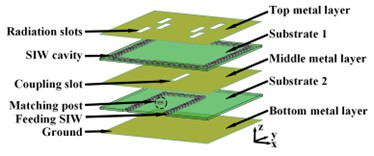
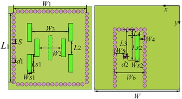
Figure 1: Configuration of the antenna element: (a) 3-D perspective, (b) overhead view of Substrate 1, and (c) overhead view of Substrate 2
The resonant frequency of TMin the SIW cavity can be calculated as follows [18]:
| (1) | ||
| (2) | ||
| (3) |
High-order modes are decided to realize dual-band antenna. To achieve dual-band radiation with a small FR, TM and TM modes with resonant frequencies of 27.47 GHz and 31.32 GHz, respectively, are employed according to Table 2, implying a FR of 1.14. All simulated results are performed by using CST Microwave Studio 2018. The E-field distributions of TM mode at 27.47 GHz and TM mode at 31.32 GHz in the SIW cavity without coupling slot excitation are shown in Fig. 2. The E-field distributions of TM mode at 27.34 GHz and TM mode at 30.12 GHz in Substrate 1 with coupling slot excitation is displayed in Fig. 3. Note that the resonant frequencies are slightly reduced owing to the existence of the coupling slot. In Fig. 3 (a), it can be clearly seen that the phases of the E-field on both sides of the coupling slot are reversed, which means that the TM mode is converted into a quasi-TM mode upon excitation. Hence, the same radiating structure can be utilized to radiate TM and TM modes simultaneously. Therefore, six slots, as radiating structures, are curved in each subregion where the standing wave reaches its peak. The slots are arranged alternatively on either side of the centerline to ensure that they emit electromagnetic energy with identical phase. Finally, TM and TM modes are radiated, thereby achieving a dual-band performance.
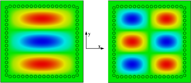
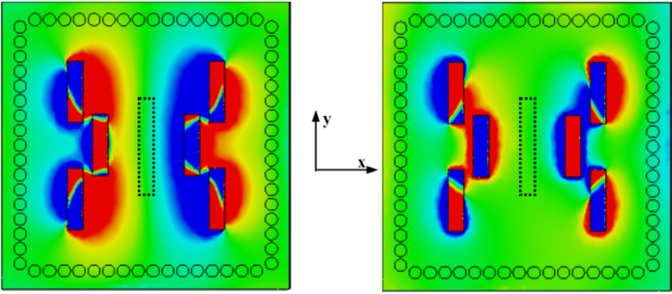
Figure 3: E-Field distributions in the SIW resonant cavity with coupling slot excitation: (a) TM mode and (b) TM mode.
C. Antenna element performance
A dual-band antenna element is achieved after optimizing the antenna parameters. As illustrated in Fig. 4, the simulated impedance bandwidths (|S| -10 dB) of the antenna element are 27.27 to 27.40 GHz and 30.07 to 30.16 GHz. The simulated peak gains are 11.1 dBi at 27.34 GHz and 10.4 dBi at 30.12 GHz, and the cross-polarization is less than -55 dB in both bands, as shown in Fig. 5.
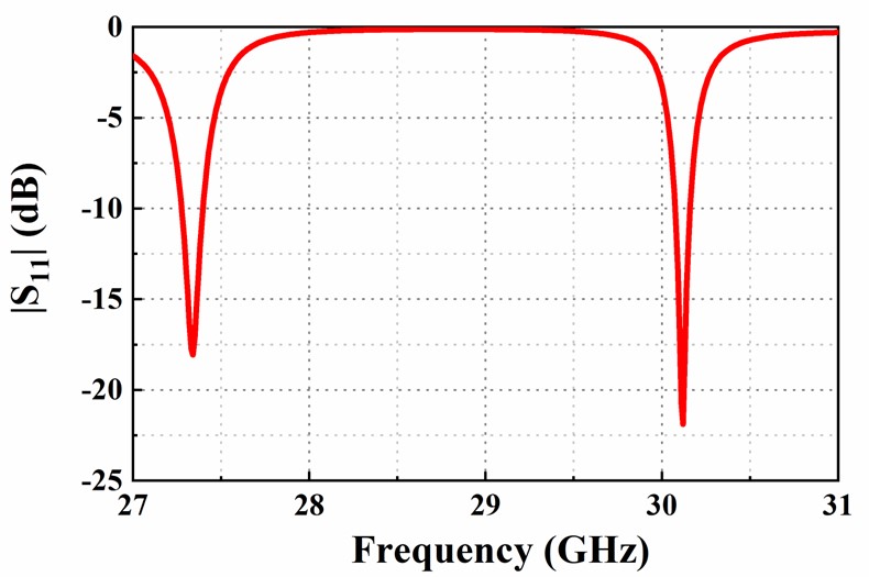
Figure 4: Simulated of the antenna element.
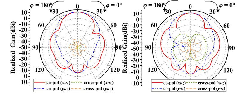
Figure 5: Simulated radiation patterns of the antenna element at (a) 27.34 GHz and (b) 30.12 GHz.
III. ANTENNA ARRAY DESIGN
A. 22 CP antenna subarray
A 22 CP subarray is first designed based on the antenna element, which can be found in Fig. 6. To achieve CP performance, an SRF network is utilized to design the antenna subarray. The antenna elements are placed sequentially on the four ports of the SRF network. In Fig. 6 (b), a 1-to-4 power divider using SRF network is designed on Substrate 2. To ensure equal power distribution among the four output ports, the lengths of the paths taken by the electromagnetic wave are carefully adjusted. A matching post is introduced in each way of the feeding network to achieve good power division and phase shift performance. Hence, the adjacent ports of the SRF network have the phase difference of 90. Therefore, the adjacent antenna elements are not only spatially orthogonal, but also the feed phase. CP performance is achieved by the antenna subarray.
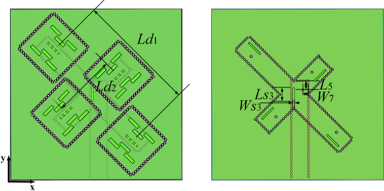
Figure 6: Geometry of the antenna subarray: (a) top view of the antenna subarray and (b) feeding network. The parameters of the antenna subarray are: mm, and .
The simulated reflection coefficient and axial-ratio (AR) of the subarray are shown in Fig. 7. Since Figs. 4 and 7 are produced by different models, these two figures are separated. The subarray achieves -10 dB impedance bandwidths at the range of 27.27-27.61 GHz and 30.14-30.38 GHz. Due to the employment of the SRF network, right-handed circularly-polarized (RHCP) radiation is achieved with bandwidths of 27.44-27.52 GHz at the lower band and 30.28-30.34 GHz at the higher band with FR of 1.1. Figure 8 displays the simulated radiation patterns of the antenna subarray, which exhibit significant directivity enhancements. The peak gains simulated by the subarray are 12.2 dBi at 27.48 GHz and 12.0 dBi at 30.31 GHz.
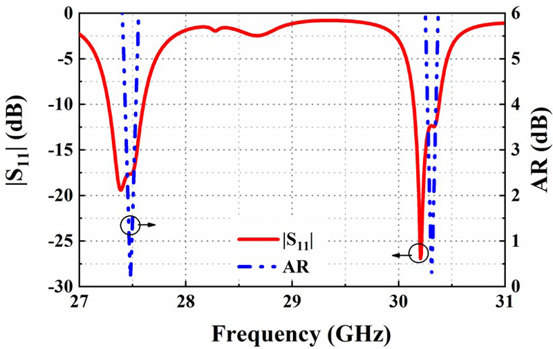
Figure 7: Simulated reflection coefficient and AR of the antenna subarray.
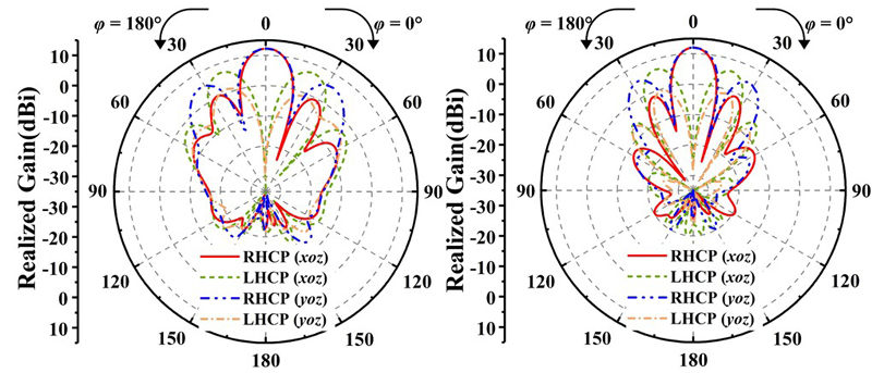
Figure 8: Simulated radiation patterns of the antenna subarray at (a) 27.48 GHz and (b) 30.31 GHz.
B. 44 CP antenna array
To improve the directivity even further, a 44 CP antenna array is developed. The overall configuration of the antenna array can be seen in Fig. 9, while the detailed geometries of the three substrates are provided in Fig. 10. which contains a grounded co-planar waveguide (GCPW) to SIW transition and a 1-4 power divider. The GCPW-SIW serves as the feeding port for the antenna array. The electromagnetic energy is input from the feeding port. An SIW feeding network is designed in Substrate 3 and coupled to Substrate 2 through the power divider. An SRF has been incorporated into Substrate 2 to facilitate coupling of electromagnetic energy to the antenna elements located in Substrate 1.
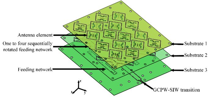
Figure 9: Configurations of the 4×4 CP antenna array.
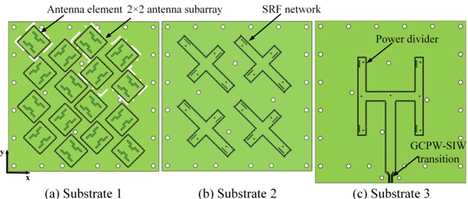
Figure 10: Detailed geometries of the three substrates.
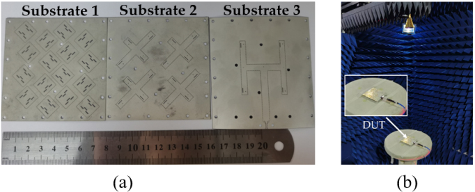
Figure 11: Photographs of the fabricated antenna array: (a) antenna array prototype and (b) measurement setup.
IV. RESULTS AND DISCUSSIONS
The 44 CP antenna array is fabricated as shown in Fig. 11 (a), and the anechoic chamber for testing the far-field radiation pattern is presented in Fig. 11 (b). The |S| of the antenna is measured using an Agilent vector analyzer E8363B. Comparison between the simulated and measured |S| and AR results can be seen in Fig. 12. The measurement results are consistent with the simulation results. At the lower band, the simulated and measured impedance bandwidths are 27.43-27.83 GHz and 27.35-27.96 GHz, while both simulated and measured 3-dB AR bandwidths are within the range of 27.63-27.72 GHz and 27.66-27.78 GHz, respectively. At the higher band, the simulated and measured impedance bandwidths are 30.28-30.52 GHz and 29.62-30.58 GHz. For AR bandwidths, they lie within a range of 30.37-30.44 GHz and 30.34-30.45 GHz, respectively. The measured results indicate that a small FR of 1.1 is achieved. The measured bandwidths are slight wider than the simulations, which is most likely due to the air gap between the different substrates.
Figures 13 and 14 depict the normalized radiation patterns of the proposed antenna array at frequencies of 27.68 GHz and 30.41 GHz, respectively. The simulated and measured radiation patterns and gain are in good agreement for both bands. The measured 3-dB AR beamwidths at 27.68 GHz are approximately 11 in the xoz-plane and 9 in the yoz-plane, respectively. Similarly, the measured 3-dB AR beamwidths are approximately 9 in the xoz-plane and 7 in the yoz-plane, respectively, at 30.41 GHz. The cross-polarization levels of the main beams remain below -28 dB for both operating bands The simulated and measured peak gains of the antenna array are 18.8 dBi and 16.9 dBi at the lower band, as well as 18.5 dBi and 16.8 dBi at the higher band, respectively. Sidelobe levels remain under -9 dB for both bands. The discrepancies between simulated results versus measurement may be attributed to fabrication inaccuracies or assembly errors during antenna construction process.
Table 3 compares the performance between the proposed antenna and some previous dual-band CP antennas. The proposed antenna array has advantages of a small FR 1.1, while keeping high gain, dual-band and CP performances.
In this paper, a dual-band CP SIW slot antenna array based on high-order modes is proposed. The antenna element achieves dual-band performance and a small FR by radiating TM and TM modes simultaneously. To achieve CP performance, an SRF network is used to firstly design a 22 CP antenna subarray. Furthermore, a 44 CP antenna array is further constructed to enhance the directivity. Measurement results show that the antenna array achieves RHCP performance in both bands. The proposed antenna could find applications in modern mmWave communication systems.
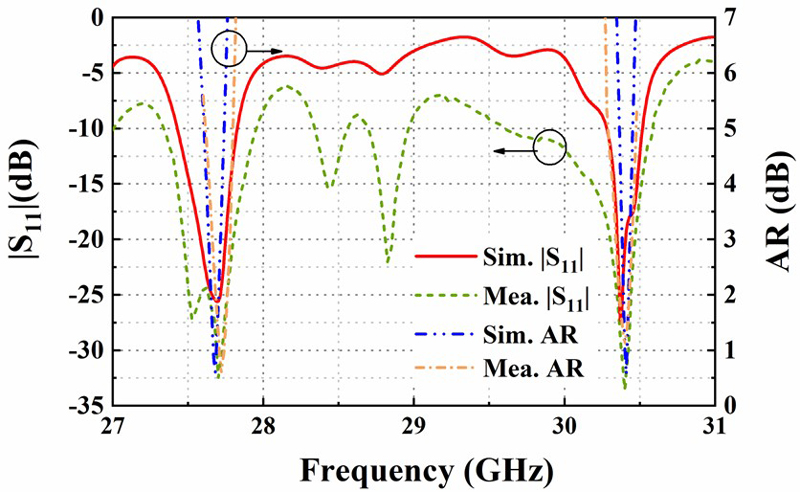
Figure 12: Simulated and measured and AR.
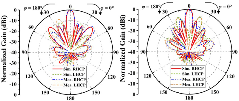
Figure 13: Simulated and measured normalized radiation patterns at 27.68 GHz (a) and (b) .
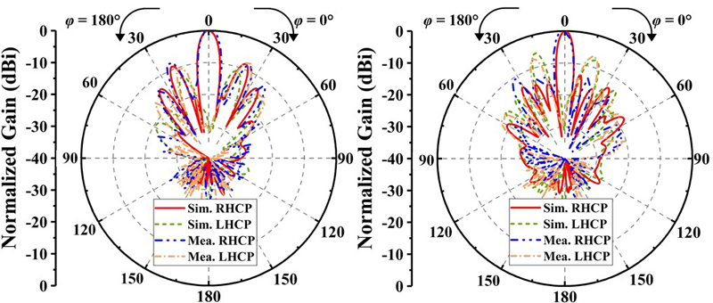
Figure 14: Simulated and measured normalized radiation patterns at 30.41 GHz (a) and (b) .
Table 3: Comparison with previous dual-band CPantennas
| Reference | Technique | FR | Imp. BW |
| [13] | Microstrip | 1.12 | |
| [19] | Microstrip | 1.42 | |
| [20] | Patch | 1.1 | |
| [21] | Patch | 1.55 | |
| Proposed | SIW |
ACKNOWLEDGMENT
This work was supported in part by the National Key R&D Program of China under Grant 2021YFA0717500, in part by the ”Siyuan Scholar” Fellowship of XJTU, and in part by the Shaanxi Province Innovation Capability Support Program under Grant 2023KJXX-130.
REFERENCES
[1] Y. Z. Tian, O. Y. Jun, P. F. Hu, and Y. M. Pan, “Millimeter-wave wideband circularly polarized endfire planar magneto-electric dipole antenna based on substrate integrated waveguide,” IEEE Antennas Wirel. Propag. Lett., vol. 21, no. 1, pp. 49-53, 2022.
[2] B. T. Feng, J. X. Lai, K. Chung, T. Y. Chen, Y. Y. Liu, and C. Y. D. Sim, “A compact widebandcircularly polarized magneto-electric dipole antenna array for 5G millimeter-wave application,” IEEE Trans Antennas Propag., vol. 68, no. 9, pp. 6838-6843, 2020.
[3] S. B. T. Naganathan, S. Dhandapani, and T. Packirisamy, “Analysis of super-solar integrated patch antenna for sub-6 GHz and beyond 6 GHz millimeter wave 5G applications,” Applied Computational Electromagnetics Society (ACES) Journal, vol. 37, no. 10, pp. 1039-1050, 2022.
[4] C. M. Zhu, G. H. Xu, D. W. Ding, J. Wu, W. Wang, Z. X. Huang, and X. L. Wu, “Low-profile wideband millimeter-wave circularly polarized antenna with hexagonal parasitic patches,” IEEE Antennas Wirel. Propag. Lett., vol. 20, no. 9, pp. 1651-1655, 2021.
[5] H. F. Xu, J. Y. Zhou, K. Zhou, Q. Wu, Z. Q. Yu, and W. H, “Planar wideband circularly polarized cavity-backed stacked patch antenna array for millimeter-wave applications,” IEEE Trans Antennas Propag., vol. 66, no. 10, pp. 5170-5179,2018.
[6] Y. M. Hussein, M. K. A. Rahim, N. A. Murad, H. O. Hanoosh, and N. B. M. Nadzir, “Substrate integrated waveguide antenna at millimeter wave for 5G application,” Applied Computational Electromagnetics Society (ACES) Journal, vol. 37, no. 4, pp. 478-484, 2022.
[7] L. Zhang, K. Wu, S. W. Wong, Y. J. He, P. Chu, W. T. Li, K. X. Wang, and S. Gao, “Wideband high-efficiency circularly polarized SIW-fed S-dipole array for millimeter-wave applications,” IEEE Trans Antennas Propag., vol. 68, no. 3, pp. 2422-2427, 2020.
[8] S. S. Marasht, M. S. Sharawi, and A. Zhu, “Dual-band circularly polarized antenna array for 5G millimeter-wave applications,” IEEE Open Journal Antennas Propag., vol. 3, pp. 314-323, 2022.
[9] C. M. Zhu, G. H. Xu, A. D. Ren, W. Wang, Z. X. Huang, and X. L. Wu, “A compact dual-band dual-circularly polarized SIW cavity-backed antenna array for millimeter-wave applications,” IEEE Antennas Wirel. Propag. Lett., vol. 21, no. 8, pp. 1572-1576, 2022.
[10] S. Liu, W. Wu, and D.-G. Fang, “Dual-band dual-circularly polarized antenna array with printed ridge gap waveguide,” IEEE Trans Antennas Propag., vol. 69, no. 8, pp. 5118-5123, 2021.
[11] H. Xu, Z. J. Chen, H. W. Liu, L. Chang, T. T. Huang, S. Ye, L. Zhang, and C. Du, “Single-fed dual-circularly polarized stacked dielectric resonator antenna for K/Ka-band UAV satellite communications,” IEEE Trans Vehicular Tech., vol. 71, no. 4, pp. 4449-4453, 2022.
[12] X. Y. Yu, S. F. Wu, J. X. Li, K. D. Xu, S. Yan, and J. Chen, “Dual-band circularly-polarized SIW antenna array using high-order modes in Ka-band,” in International Conference on Electronic Information and Communication Technology (ICEICT), 2022.
[13] Y. H. Xu, L. Zhu, N. W. Liu, and M. Li, “A dual-band dual-circularly-polarized slot antenna with stable in-band gain and reduced frequency ratio under triple resonance,” IEEE Trans Antennas Propag., vol. 70, no. 11, pp. 10199-10206, 2022.
[14] Y. H. Xu, L. Zhu, and N. W. Liu, “Design approach for a dual-band circularly polarized slot antenna with flexible frequency ratio and similar in-band gain,” IEEE Antennas Wirel. Propag. Lett., vol. 21, no. 5, pp. 1037-1041, 2022.
[15] Q. S. Wu, X. Zhang, L. Zhu, J. Wang, G. Zhang, and C. B. Guo, “A single-layer dual-band dual-sense circularly polarized patch antenna array with small frequency ratio,” IEEE Trans Antennas Propag., vol. 70, no. 4, pp. 2668-2675, 2022.
[16] T. Zhang, W. Hong, Y. Zhang, and K. Wu, “Design and analysis of SIW cavity backed dual-band antennas with a dual-mode triangular-ring slot,” IEEE Trans Antennas Propag., vol. 62, no. 10, pp. 5007-5016, 2014.
[17] H. K. Chen, Y. Shao, Y. J. Zhang, C. H. Zhang, and Z. Z. Zhang, “Low-profile millimeter-wave SIW cavity-backed dual-band circularly polarized antenna,” IEEE Trans Antennas Propag., vol. 65, no. 12, pp. 7310-7315, 2017.
[18] F. Xua and K. Wu, “Guided-wave and leakage characteristics of substrate integrated waveguide,” IEEE Trans Antennas Propag., vol. 53, no. 1, pp. 66-73, 2005.
[19] J. D. Zhang, L. Zhu, N. W. Liu, and W. Wu, “Dual-band and dual-circularly polarized single-layer microstrip array based on multiresonant modes,” IEEE Trans Antennas Propag., vol. 65, no. 3, pp. 1428-1433, 2017.
[20] Z. Wang, R. She, and J. Han, “Dual-band dual-sense circularly polarized stacked patch antenna with a small frequency ratio for UHF RFID reader applications,” IEEE Access, vol. 5, pp. 15260-115270, 2017.
[21] B. C. Park and J. H. Lee, “Dual-band omnidirectional circularly polarized antenna using zeroth- and first-order modes,” IEEE Antennas Wirel. Propag. Lett., vol. 11, pp. 407-410, 2012.
BIOGRAPHIES

Jianxing Li received the B.S. degree in information and communications engineering, and the M.S. and Ph.D. degrees in electromagnetic field and microwave techniques from Xi’an Jiaotong University, Xi’an, China, in 2008, 2011, and 2016, respectively. He is currently a full Professor with Xi’an Jiaotong University. His research interests include microwave and mmWave circuits and antennas, wireless power transfer, and multifunctional mmWave antennas.

Xiaoyan Yu received the bachelor’s degree in information and telecommunication engineering from Xi’an Jiaotong University, Xi’an, China, in 2021. She is currently pursuing the master’s degree in electronics science and technology, from Xi’an Jiaotong University, Xi’an. Her current research interests include SIW antenna array and mm-Wave circularly-polarized antenna array.

Sifan Wu received the B.S. degree in information engineering and business administration from Xi’an Jiaotong University, Xi’an, China, in 2020, where he is currently pursuing the Ph.D. degree in electronics science and technology. His current research interests include 3-D-printed millimeter-wave filters and antenna arrays. Mr. Wu received the Best Student Paper at the 2021 National Conference on Antennas and the Best Student Paper Award at the 2022 IEEE International Conference on Electronic Information and Communication Technology (ICEICT).

Sen Yan received the bachelor’s and master’s degrees in information and telecommunication engineering from Xi’an Jiaotong University, Xi’an, China, in 2007 and 2010, respectively, and the Ph.D. degree in electrical engineering from Katholieke Universiteit Leuven (KU Leuven), Leuven, Belgium, in 2015. He has authored and coauthored more than 150 international journal and conference contributions. His research interests include microwave metamaterials and metasurfaces, wearable devices and textile antennas, antenna diversity, and microwave biosensors.

Kai-Da Xu received the B.E. and Ph.D. degrees in electromagnetic field and microwave technology from the University of Electronic Science and Technology of China (UESTC), Chengdu, China, in 2009 and 2015, respectively. He has authored and coauthored over 160 articles in peer-reviewed journals and over 50 papers in conference proceedings. His current research interests include RF/microwave, millimeter-wave/THz devices, and antenna arrays.
ACES JOURNAL, Vol. 39, No. 10, 901–907
doi: 10.13052/2024.ACES.J.391008
© 2024 River Publishers