Miniaturized Wideband Circularly Polarized Triangular Patch Antennas based on Characteristic Mode Analysis
Tian-Long Yang, Xiao Zhang, Qiong-Sen Wu, and Tao Yuan
1College of Electronics and Information Engineering
Shenzhen University, Shenzhen, 518060, China
xiao.zhang@szu.edu.cn
*Corresponding Author
2School of Integrated Circuits
Guangdong University of Technology, Guangzhou, 510006, China
Submitted On: June 28, 2023; Accepted On: October 8, 2023
ABSTRACT
A miniaturized, wideband circularly polarized (CP) antenna based on coupled triangular patches is presented. Initially, two identical triangular patches with shorting pins are placed close to each other in a perpendicular orientation. Hence, a pair of orthogonal modes can be produced based on the coupled resonators. Under the characteristic mode analysis (CMA), it can be found that the 90 phase difference is achieved by modulating gap distance and shorting pins numbers. Both the shape of triangle patches and shorting pins contribute to the miniaturization. To further improve the AR bandwidth, a third patch is added to form a new mode. Thanks to the triple modes produced by the three patch elements, two AR minima are constructed to broaden the AR bandwidth. With this compact arrangement and shorting pins, a miniaturized wideband CP patch antenna with a 5.2% AR bandwidth is successfully implemented. The overall size of the antenna is merely .
Keywords: Antenna miniaturization, characteristic mode analysis, circularly polarized patch antennas, triangular patches, wideband patch antennas.
I. INTRODUCTION
Wideband circularly polarized (CP) patch antennas play an important role in wireless communication and sensing systems. They are also capable of consistent polarized orientation between transmitter and receiver, reduction of Faraday rotation effects, and mitigating multi-path distortion [1]. CP antennas with compact structures and low profiles are highly needed in size-limited devices, such as satellite communications, wireless sensors, and unmanned aerial vehicles.
Traditional CP antennas have a relatively narrow axial-ratio (AR) band because a pair of degenerate modes as orthogonal components are not able to support equal amplitude and stable 90 phase difference in wideband. To extend AR bandwidths, three kinds of techniques have been proposed: multi-ports feeding networks [2–7], lower quality factor [8–15], and multi-mode techniques [16–25].
The first technique, using dual-ports [2–4] and sequential-phase [5–7] feed networks, can introduce additional AR bandwidth. However, the extraordinarily coupled resonators would inevitably increase the patch antenna’s profile [2] and occupy more space [3–4]. Power divider [5] also decreases antennas’ total efficiency, and shorting strips [6–7] between antennas make the system not suitable for integration. The second technique is to decrease the quality factor of antennas, which can be realized by a thicker substrate [8–15]. To compensate inductance of the probe and realize impedance matching, the capacitive coupling feed [8–9, 13–15] and slot-loaded patch [10–13] are proposed. However, the increased AR bandwidths are still limited, and antennas are relatively thick. The third technique, based on the multi-mode technique, can introduce more AR minima and increase AR bandwidths. For instance, metasurface [17], stacked patches [16, 18], and parasitic patches [20–21] are introduced above or around the driven patch as parasitic elements. Fewer numbers of parasitic patch elements can also be realized if a 90 phase difference is introduced between adjacent elements [22–23] or modes [24–25]. In [22], a quantitative design method based on the equivalent circuit model is proposed. With this method, multiple minima in the axial ratio response are produced by employing several adjacent coupled radiators, resulting in wideband CP radiation. In general, half-wavelength resonators or high-order modes are usually utilized to design wideband CP antennas, whereas there is little consideration for miniaturization.
In this paper, miniaturized wideband CP patch antennas using coupled radiators are proposed. To begin with, a narrow band CP antenna is designed based on a pair of closely spaced triangular patch antennas with shorting fences, as shown in Fig. 1 (a). A 90 phase difference is achieved between two orthogonal patches due to the electromagnetic coupling for fringing fields. It can be flexibly adjusted by different gap dimensions and pin numbers. After that, the third patch is coupled with the former ones to produce triple modes in general. The whole of them can generate two AR minima and extend CP bandwidth, as shown in Fig. 1 (b). Different from traditional wideband CP antennas, the proposed one is based on multi-modes generated by multi-radiators instead of two adjacent elements. Besides, both the quarter-wavelength triangle patches and sequentially close arrangement in a counterclockwise direction contribute to a more compact and miniaturized antenna prototype.
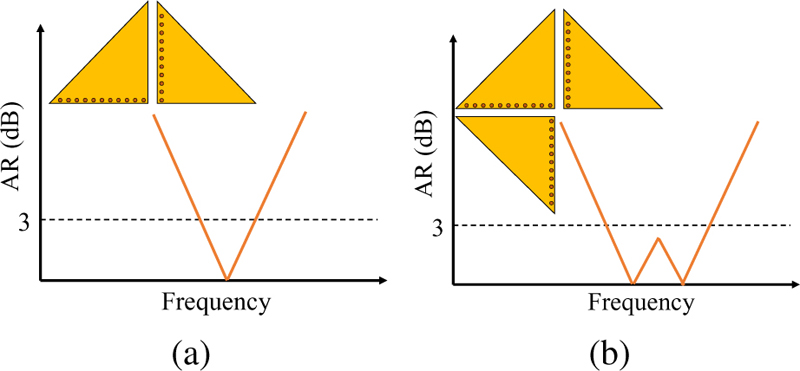
Figure 1: Process of the evolution of the proposed CP antenna: (a) CP antenna I with single AR minimum and (b) wideband CP antenna II with two AR minima.
II. NARROW BAND CP PATCH ANTENNA WITH ONE AR MINIMUM
A miniaturized narrow band CP patch antenna is proposed in this section, as shown in Fig. 2. A pair of triangular patches are printed on the top of the 0.813 mm-thick dielectric substrate Rogers4003 ( = 3.55, tan = 0.003). They are arranged orthogonally, and both are closely spaced to be coupled with each other. A row of shorting pins is inserted at the right-angle edge of each patch. Hence the patches can operate at quarter-wavelength modes. The hypotenuse of triangular patches can also contribute to miniaturization. A coaxial probe is soldered on the finite ground to excite two orthogonal modes simultaneously, which will be demonstrated in the following using characteristic modeanalysis.
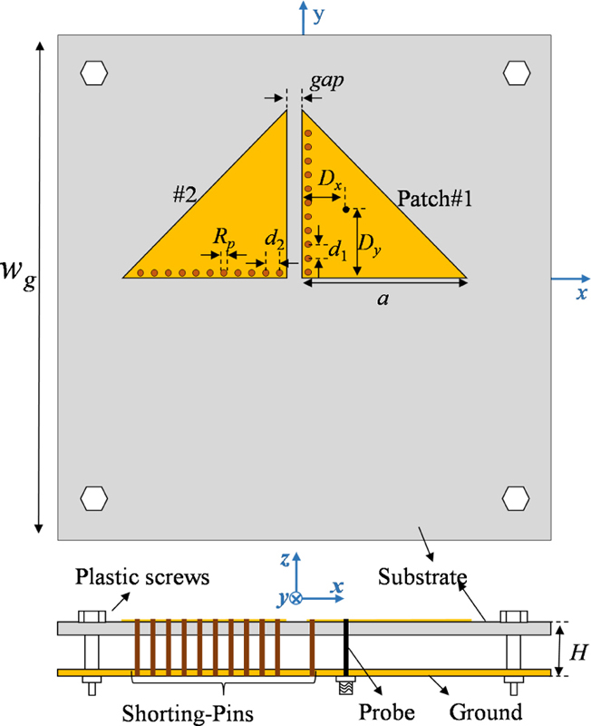
Figure 2: Geometry of the proposed CP patch antenna I. Dimensions are , gap , (unit: mm), pin number .
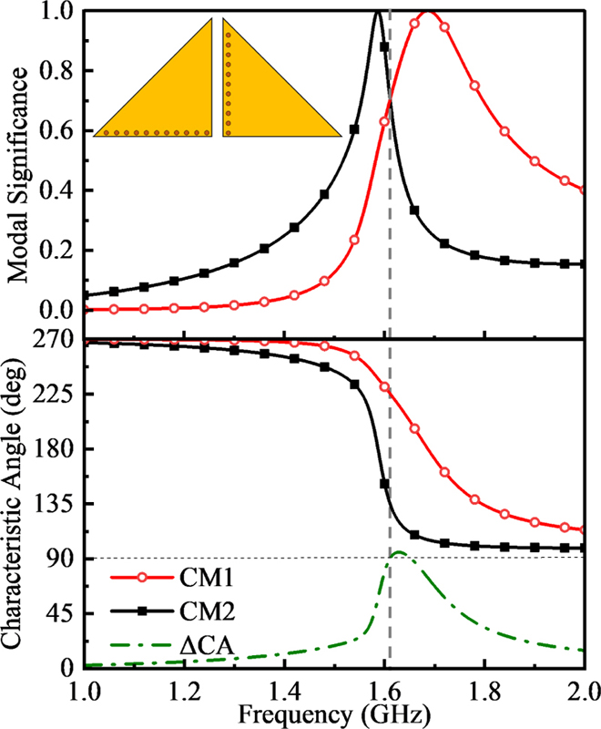
Figure 3: MS and CA of CP patch antenna I.
A. CMA of two coupled triangular patches
Characteristic mode theory is full of physical meaning, and it is effective in antenna design to reveal the operating modes. Following the theory of characteristic modes (CMs) for PEC objects [26–27], a generalized eigenvalue equation can be written as
| (1) |
where is the eigenvalue associated with each characteristic current and J. R, and X are the real and imaginary Hermitian parts of the matrix Z, respectively. Model significance (MS) and characteristic angle (CA) are other two helpful indicators, and they are defined as
| (2) |
| (3) |
The associated modes are resonant modes when = 0, MS = 1, and CA = 180. In characteristic mode analysis (CMA), a pair of orthogonal modes with equal amplitude and 90 phase difference can be used to produce CP waves [28]. The difference in the two modes’ characteristic angles is related to the phase difference of their radiated far fields. If the port is placed where the two modes have equal characteristic current amplitude, modal significance can reflect the amplitude of CMs. In this work, the CST Studio Suite 2021 will be used to analyze the CMs of antennas.
To reveal the working principle of the proposed narrow band CP patch antenna I in Fig. 2, CMA is conducted with an infinite substrate and ground plane. Its modal significance and characteristic angle are shown in Fig. 3. There are two potential CMs in the operating band of antenna I. CM1 and CM2 are resonant at 1.586 GHz and 1.686 GHz, respectively. Note that the 90 phase difference between the two CMs is achieved because of electromagnetic coupling between two identical antennas [29]. Besides, both share the same magnitude of modal significance (MS) at 1.603 GHz. To excite the two modes with the same amplitude, shown in Fig. 2, the probe is fed the right patch #1 where the current magnitude of the two modes is approximately equal.
Characteristic currents as well as modal patterns are also depicted in Fig. 4. It can be found that the two modes have orthogonal characteristic currents in Figs. 4 (a) and (b). For CM1, the total equivalent currents mainly flow in 45 direction, while for CM2 the total equivalent currents mainly flow in +45 direction. Figs. 4 (c) and (d) show the modal radiation patterns of the CMs. It shows that both modes have broadside radiation patterns.
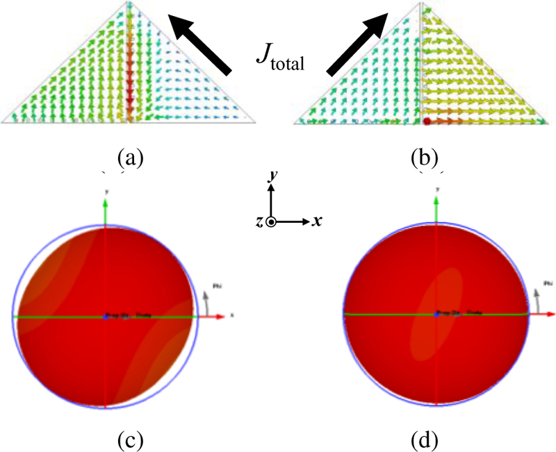
Figure 4: Characteristic currents and modal radiation patterns of the antenna I: (a) and (c) CM1 at 1.586 GHz, (b) and (d) CM2 at 1.686 GHz.
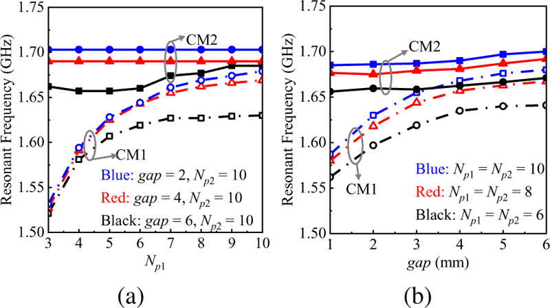
Figure 5: Modes’ resonant frequencies of proposed antenna I as a function of (a) varied and (b) varied gap.
B. Parametric study
Coupling strength between two adjacent resonators is of great importance in designing bandpass filters. In the same way, it is also the key to designing CP antennas based on coupled resonators. To achieve the required 90 phase difference between the two modes, a parametric study of the proposed antennas is conducted. In brief, both the coupling gap between the two patches and the number of loaded pins are the key parameters to modulating the coupling strength.
Increasing the number of loaded pins in the patch #1 (N) can dramatically raise CM1’s resonant frequency. For example, in Fig. 5 (a), increasing N from 3 to 10 leads to an increase in the resonant frequency of CM1 from 1.53 to 1.68 GHz when gap = 2 mm, N = 10. However, the resonant frequency of CM2 remains approximately constant at 1.703 GHz.
Gap distance can also dramatically affect CM1’s resonant frequency. In Fig. 5 (b), by increasing gap distance between patches, the resonant frequency of CM2 is almost unchanged while that of CM1 rises under the condition of fixed pins N and N
To obtain further insight into how the pin number and gap width impact the CP performance, the full-wave simulation is carried out. The magnitude and phase difference of E and E at broadside with different pin numbers, and gap dimensions are shown in Figs. 6 and 7, respectively. In Fig. 6 (a), although N varies from 4 to 10, the frequency with |E| = |E| is maintained at 1.58 GHz. However, the phase difference has decreased with increased N. In Fig. 6 (b), the AR responses with respect to different values of N show that the AR minimum occurs at 1.58 GHz. The sole AR minimum will degenerate with fewer pins, as a result of phase change.
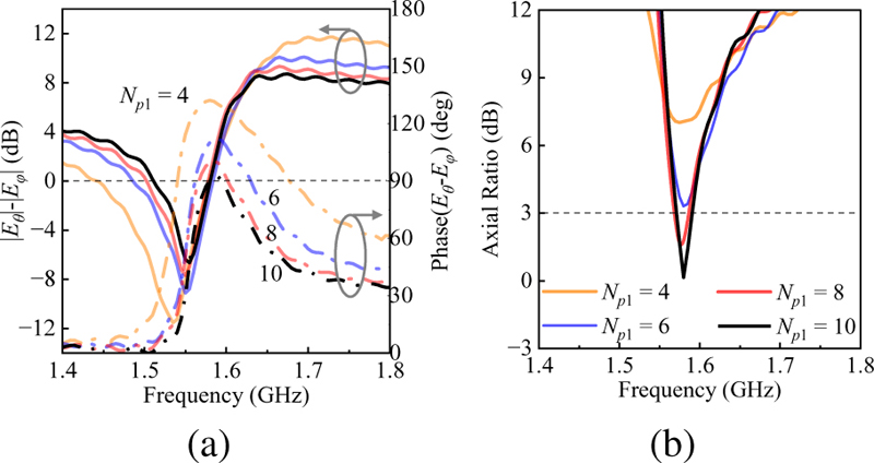
Figure 6: Simulated results of antenna I with respect to different values of : (a) magnitude and phase difference of and at broadside and (b) AR responses at broadside.
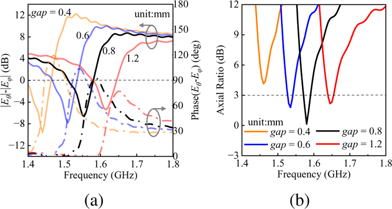
Figure 7: Simulated results of antenna I with respect to different values of gap: (a) Magnitude and phase difference of and at broadside and (b) AR responses at broadside.
In Fig. 7 (a), as the gap varies from 0.4 to 1.2 mm, the frequency with |E| = |E| rises from 1.465 to 1.645 GHz. The phase difference decreases at the same time. The frequency of the AR minimum also varies from 1.465 to 1.645 GHz. When the gap equals 0.8 mm, both the same amplitude and a 90 phase difference are satisfied simultaneously. As a result, the best CP performance with a minimum AR value of 0.15 dB is successfully achieved at 1.58 GHz. The 3dB-AR bandwidth is from 1.57 to 1.59 GHz (1.3%), as shown in the black curve in Fig. 7 (b).
III. WIDEBAND CP PATCH ANTENNA WITH TWO AR MINIMA
To further improve the AR bandwidth, the third patch is coupled with the former two patches to introduce the second AR minimum. The wideband CP triangle patch antenna II with detailed dimensions is proposed as shown in Fig. 8. Each patch element has the same dimension, and they are printed on the 0.813 mm-thick dielectric substrate Rogers4003 ( = 3.55, tan = 0.003). Three isosceles right-triangular patches are positioned sequentially along a counter-clockwise path to be orthogonal with each other. All of them are closely placed to be strongly coupled with each element by fringing fields. There is also different gap distance between two adjacent elements. To further miniaturize the overall size, each patch is loaded with a different number of shorting pins. Thanks to the constructed short circuit boundary, this enables the patch to operate in quarter wavelength mode.
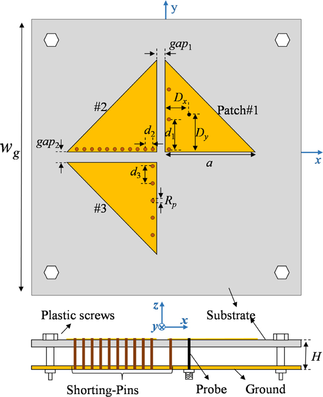
Figure 8: Geometry of the proposed wideband patch antenna II. Dimensions are , gap 2.6, gap (unit: mm), pin number .
A. Characteristic mode analysis and design of three coupled triangular patches
Characteristic mode analysis is conducted to reveal the working principle of the proposed wideband CP antenna shown in Fig. 8. The substrate and ground plane are set infinite in the multilayer solver of CST. In Fig. 9, modal significance and characteristic angle show that there are three potential CMs in the working band for antenna II. Three modes respectively resonate at 1.554, 1.612, and 1.82 GHz. Hence, they can be recognized as two pairs of adjacent modes (CM1 and CM2, CM2 and CM3). It can be found that there is a 90 phase difference and equal MS occurring at 1.575 and 1.663 GHz. Meanwhile, the phase of CM1 delays behind CM2, and that of CM2 delays behind CM3. Thanks to the same phase delay between two pairs of adjacent modes, the two pairs of modes can produce the same sense of CP waves to enhance the CP bandwidth.
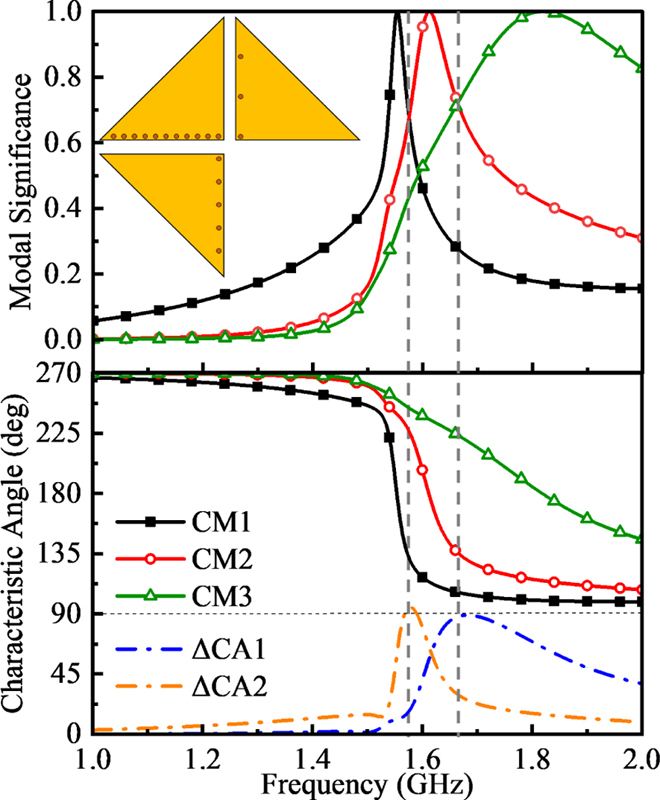
Figure 9: MS and CA of CP patch antenna II.
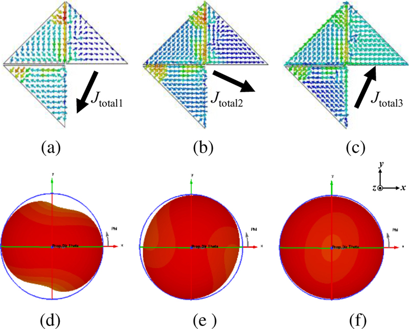
Figure 10: Characteristic currents and modal radiation patterns of the antenna II. (a) and (d) CM1 at 1.554GHz. (b) and (e) CM2 at 1.612 GHz. (c) and (f) CM3 at 1.8GHz.
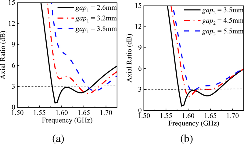
Figure 11: Simulated AR responses of antenna II with respect to different coupling gap widths of (a) and (b) .
Figure 10 shows the associated characteristic currents and modal radiation patterns of the CMs at their resonant frequencies. The currents of each two adjacent modes are orthogonal to each other. The total equivalent surface currents of CM1 and CM3 are in opposite directions, and both are orthogonal to that of CM2. Besides, all the CMs can generate broadside radiation patterns. To excite the three CMs, a coaxial probe is placed beneath the patch #1, where the current magnitude of each CMs is almost the same.
In the previous section, the relationship between AR responses and different gap dimensions as well as pin numbers was discussed. It is found that they both can affect the magnitude and the phase difference of the CMs to some extent. Considering that the probe position is selected on patch #1, the pin numbers on it (N) should not be too large because the input impedance will become too low to be matched. Thus, it is suggested to first determine the pin numbers on each patch in the design. After that, the parametric analysis is conducted on the gap distance (gap and gap).
In this section, a compact and miniaturized wideband CP antenna is proposed where two AR minima are introduced to broaden AR bandwidth. When gap is equal to 2.6 mm and gap is equal to 3.5 mm, the best CP performance can be realized. On the one hand, the first AR minimum is sensitive to the value of gap as shown in Fig. 11 (a). When gap varies from 2.6 to 3.8 mm, the first AR minimum tends to deteriorate at a high value of 7.9 dB. On the other hand, the second AR minimum point is sensitive to the variations in gap. When gap reaches 5.5 mm, the second AR minimum tends to reach 3.5 dB. Hence it can also affect the CP performance. The best CP performance will be achieved if the coupling gaps are further optimized.
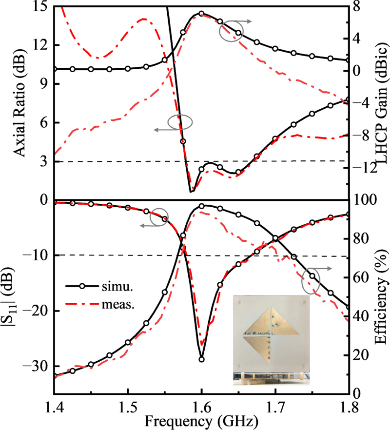
Figure 12: Measured and simulated ARs, LHCP gains, S-parameters, and efficiency of antenna II.
B. Simulated and measured results
To verify the validity of the proposed wideband CP patch antenna, the prototype of the antenna is simulated, fabricated, and tested. The S-parameter and radiation patterns are measured by the R&S ZVA-40 vector network analyzer and the near-field chamber, respectively.
Figure 12 shows the simulated and measured broadside AR and left-handed circular polarized (LHCP) gain of the proposed antenna. Right-handed CP can also be realized if the probe is soldered at the second patch. The measured AR data matches well with the simulated one. The measured 3 dB-AR bandwidth is from 1.58 to 1.67 GHz (5.5%), and the simulated one is from 1.58 to 1.665 GHz (5.2%). The measured LHCP gain at a higher frequency is slightly lower than the simulated value because the real material loss is higher than the simulated value. The average LHCP gain of the measured and simulated are approximately 5.05 and 5.7 dBic, respectively. The simulated and measured reflection coefficients and efficiencies are also depicted in Fig. 12. The simulated and measured 10 dB matching bandwidths are both from 1.58 to 1.665 GHz (5.2%). The measured efficiency is slightly lower than the simulated one at the higher frequency, which may be because that the tan of the fabricated material is higher than the simulated setting one.
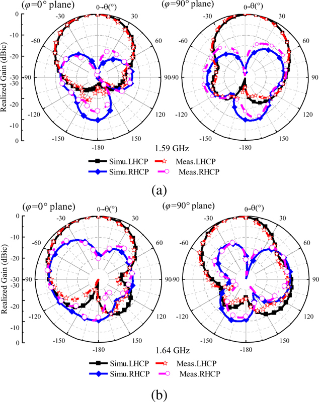
Figure 13: Measured and simulated radiation patterns of Antenna II: (a) 1.59 GHz and (b) 1.64 GHz.
Figure 13 shows the simulated and measured radiation patterns at two AR minima, 1.59 and 1.64 GHz. At broadside, the LHCP high cross-polarization ratios are achieved, which are up to 27 dB and 18 dB at 1.59 GHz and 1.64 GHz, respectively. The maximum beam direction at higher frequencies is slightly tilted, and the cross-polarization rises with increased theta angle because of the current asymmetry of the three modes.
IV. CONCLUSION
In this paper, a miniaturized wideband CP antenna has been proposed based on coupled triangular patch elements. Initially, two perpendicular patch radiators are closely spaced to be coupled with each other. Two rows of shorting pins are inserted, and the patch can operate at quarter-wavelength modes. Hence, the shorting pins and antenna arrangement contribute to antenna miniaturization. By means of CMA, we can find that gap dimension and pins numbers are key parameters for manipulating the phase difference between CMs and generating a minimum AR value. Subsequently, the third patch is introduced, and a widened bandwidth with two AR minima is achieved by allocating its three CMs. The AR bandwidth is enhanced up to 5.2% in a small overall size of 0.340.046. Hence, the proposed CP antenna will be a good candidate in modern wireless communication systems to meet miniaturized and wideband requirements.
ACKNOWLEDGMENT
This work was supported in part by the Guangdong Provincial Department of Science and Technology, China, under Project No. 2020B1212030002, in part by the Shenzhen Science and Technology Innovation Commission, China, under Construction and Operation Project of Guangdong Provincial Key Laboratory and Guangdong-Hong Kong-Macau Joint Laboratory and Projects (No. JCYJ20190808115411853, No. CJGJZD2022051714240411, and No. KQTD20180412181337494), in part by the Postgraduate Education Branch of the China Education Society of Electronics, and in part by the Guangdong Provincial Department of Education, China, under the Innovation Team Project No. 2020KCXTD004.
REFERENCES
[1] S. Gao, Q. Luo, and F. Zhu, Circularly Polarized Antennas. Hoboken, NJ, USA: Wiley-IEEE Press, Nov. 2013.
[2] K. L. Wong and T. W. Chiou, “Broad-band single-patch circularly polarized microstrip antenna with dual capacitively coupled feeds,” IEEE Trans. Antennas Propagat., vol. 49, no. 1, pp. 41-44, Jan. 2001.
[3] Q.-S. Wu, X. Zhang, and L. Zhu, “A wideband circularly polarized patch antenna with enhanced axial ratio bandwidth via co-design of feeding network,” IEEE Trans. Antennas Propagat., vol. 66, no. 10, pp. 4996-5003, Oct. 2018.
[4] Q. S. Wu, X. Zhang, and L. Zhu, “A feeding technique for wideband CP patch antenna based on 90 degrees phase difference between tapped line and parallel coupled line,” IEEE Trans. Antennas Propagat., vol. 18, no. 7, pp. 1468-1471, July 2019.
[5] Y. J. Hu, W. P. Ding, and W. Q. Cao, “Broadband circularly polarized microstrip antenna array using sequentially rotated technique,” IEEE Antennas Wireless Propagat. Lett., vol. 10, pp. 1358-1361, 2011.
[6] Y. Li, Z. J. Zhang, and Z. H. Feng, “A sequential-phase feed using a circularly polarized shorted loop structure,” IEEE Trans. Antennas Propagat., vol. 61, no. 3, pp. 1443-1447, Mar. 2013.
[7] C. J. Deng, Y. Li, Z. J. Zhang, and Z. H. Feng, “A wideband sequential-phase fed circularly polarized patch array,” IEEE Trans. Antennas Propagat., vol. 62, no. 7, pp. 3890-3893, July 2014.
[8] B. P. Kumar, D. Guha, and C. Kumar, “Reduction of beam squinting and cross-polarized fields in a wideband CP element,” IEEE Antennas Wireless Propagat. Lett., vol. 19, no. 3, pp. 418-422, Mar. 2020.
[9] J. M. Kovitz and Y. Rahmat-Samii, “Using thick substrates and capacitive probe compensation to enhance the bandwidth of traditional CP patch antennas,” IEEE Trans. Antennas Propagat., vol. 62, no. 10, pp. 4970-4979, Oct. 2014.
[10] A. Khidre, K. F. Lee, F. Yang, and A. Z. Elsherbeni, “Circular polarization reconfig urable wideband E-shaped patch antenna for wireless applications,” IEEE Trans. Antennas Propagat., vol. 61, no. 2, pp. 960-964, Feb. 2013.
[11] J. Yin, Q. Wu, C. Yu, H. Wang, and W. Hong, “Broadband symmetrical E-shaped patch antenna with multimode resonance for 5G millimeter-wave applications,” IEEE Trans. Antennas Propagat., vol. 67, no. 7, pp. 4474-4483, July 2019.
[12] K. Y. Lam, K. M. Luk, K. F. Lee, H. Wong, and K. B. Ng, “Small circularly polarized U-slot wideband patch antenna,” IEEE Antennas Wireless Propagat. Lett., vol. 10, pp. 87-90, 2011.
[13] S. S. Yang, K.-F. Lee, A. A. Kishk, and K.-M. Luk, “Design and study of wideband single feed circularly polarized microstrip antennas,” Prog. Electromagn. Res., vol. 80, pp. 45-61, Jan. 2008.
[14] J. Wu, X. Ren, Z. Wang, and Y. Yin, “Broadband circularly polarized antenna with L-shaped strip feeding and shorting-pin loading,” IEEE Antennas Wireless Propagat. Lett., vol. 13, pp. 1733-1736, 2014.
[15] L.-L. Qiu, L. Zhu, and Y. Xu, “Wideband low-profile circularly polarized patch antenna using 90 modified Schiffman phase shifter and meandering microstrip feed,” IEEE Trans. Antennas Propagat., vol. 68, no. 7, pp. 5680-5685, July 2020.
[16] Q. W. Lin, H. Wong, X. Y. Zhang, and H. W. Lai, “Printed meandering probe-fed circularly polarized patch antenna with wide bandwidth,” IEEE Antennas Wireless Propagat. Lett., vol. 13, pp. 654-657, 2014.
[17] S.-X. Ta and I. Park, “Low-profile broadband circularly polarized patch antenna using metasurface,” IEEE Trans. Antennas Propagat., vol. 63, no. 12, pp. 5929-5934, Dec. 2015.
[18] M.-C. Tang, X. Chen, M. Li, and R. W. Ziolkowski, “A bandwidth-enhanced, compact, single-feed, low-profile, multilayered, circularly polarized patch antenna,” IEEE Antennas Wireless Propagat. Lett., vol. 16, pp. 2258-2261, 2017.
[19] G. Kumar and K. Gupta, “Broad-band microstrip antennas using additional resonators gap-coupled to the radiating edges,” IEEE Trans. Antennas Propagat., vol. 32, no. 12, pp. 1375-1379, Dec. 1984.
[20] K. Ding, C. Gao, D. Qu, and Q. Yin, “Compact broadband circularly polarized antenna with parasitic patches,” IEEE Trans. Antennas Propagat., vol. 65, no. 9, pp. 4854-4857, Sep. 2017.
[21] J.-F. Lin and Q.-X. Chu, “Enhancing bandwidth of CP microstrip antenna by using parasitic patches in annular sector shapes to control electric field components,” IEEE Antennas Wireless Propagat. Lett., vol. 17, pp. 924-927, 2018.
[22] Q.-S. Wu, X.-Y. Tang, X. Zhang, L. Zhu, G. Zhang, and C.-B. Guo, “Circularly-polarized patch antennas with enhanced bandwidth based on capacitively coupled orthogonal patch radiators,” IEEE Open J. Antennas Propagat., vol. 4, pp. 472-483, 2023.
[23] Y.-H Xu, L. Zhu, N.-W. Liu, and L.-L Qiu, “An inductively coupled CP slot antenna based on intrinsic 90 phase difference and its flexible application in wideband CP radiation,” IEEE Trans. Antennas Propagat., vol. 71, no. 2, pp. 1204-1215, Feb. 2023.
[24] N.-W. Liu, L. Zhu, Z.-X. Liu, G. Fu, and Y. Liu, “Design approach of a single circularly polarized patch antenna with enhanced AR-bandwidth under triple-mode resonance,” IEEE Trans. Antennas Propagat., vol. 68, no. 8, pp. 5827-5834, Aug. 2020.
[25] J. Zeng, X. Liang, L. He, F. Guan, F. H. Lin, and J. Zi, “Single-fed triple-mode wideband circularly polarized microstrip antennas using characteristic mode analysis,” IEEE Trans. Antennas Propagat., vol. 70, no. 2, pp. 846-855, Feb. 2022.
[26] R. F. Harrington and J. R. Mautz, “Computation of characteristic modes for conducting bodies,” IEEE Trans. Antennas Propagat., vol. AP-19, no. 5, pp. 629-639, Sep. 1971.
[27] Y. Chen and C.-F. Wang, Characteristic Modes: Theory and Applications in Antenna Engineering, 1st ed., pp. 1-142, Hoboken, NJ, USA: Wiley, 2015.
[28] J.-F. Lin and L. Zhu, “Low-profile high-directivity circularly-polarized differential-fed patch antenna with characteristic modes analysis,” IEEE Trans. Antennas Propagat., vol. 69, no. 2, pp. 723-733, Feb. 2021.
[29] X. Zhang, Q. Y. Zeng, Z. P. Zhong, Q. S. Wu, L. Zhu, and T. Yuan, “Analysis and design of stable-performance circularly polarized antennas based on coupled radiators for smart watches,” IEEE Trans. Antennas Propagat., vol. 70, no. 7, pp. 5312-5323, July 2022.
BIOGRAPHIES

Tian-Long Yang was born in Zhanjiang, Guangdong, China. He received the B.Eng. degree in electronic and information engineering from Shenzhen University, Shenzhen, China, in 2021. He is currently pursuing the M.Eng. degree in communication engineering with Shenzhen University, Shenzhen, China.
His current research interests include circularly polarized antennas and terminal antennas.

Xiao Zhang (S’15-M’18) was born in Gaozhou, Guangdong, China. He received the B.Eng. degree in information engineering and the M.Eng. degree in communication and information systems from the South China University of Technology, Guangzhou, China, in 2011 and 2014, respectively, and the Ph.D. degree in electrical and computer engineering from University of Macau, Macau, SAR, China, in 2017.
From September 2012 to August 2014, he was a research assistant with Comba Telecom Systems Limited, Guangzhou, China. From January 2018 to March 2018, he was a research fellow with the Antenna and Electromagnetic-Wave Laboratory in University of Macau, Macau, SAR, China. In 2018, he joined the College of Electronics and Information Engineering, Shenzhen University, Shenzhen, China, where he is currently an associate professor. His research interests include high-gain antennas, wideband antennas, circularly-polarized antennas, terminal antennas, filtering antennas, reflectarray, and characteristic mode analysis.
Dr. Zhang was the recipient of the Scientific and Technological R&D Award for Postgraduates of Macau in 2018. He was recognized as the Shenzhen Overseas High Caliber Personnel Level C in 2018. He was recognized as a Top 2% Scientist in 2019 and 2022 by Elsevier. He also serves as a reviewer for several journals, including the IEEE Transactions on Antennas and Propagation and the IEEE Antennas and Wireless PropagationLetters.

Qiong-Sen Wu received the B.Eng. degree in information engineering and the M.Eng. degree in electromagnetism and microwave engineering from South China University of Technology, Guangzhou, China, in 2011 and 2014, respectively, and the Ph.D. degree in electrical and computer engineering from the University of Macau, Macau, SAR, China, in 2018.
He joined the Antenna and Electromagnetic-Wave Laboratory in University of Macau, Macau, SAR, China, as a research fellow in May 2018. He is currently an associate professor with the School of Integrated Circuits, Guangdong University of Technology. His current research interests include microwave circuits and planar antennas with improved functionalities. He also serves as a reviewer for several journals, including the IEEE Transactions on Antennas and Propagation and the IEEE Transactions on Microwave Theory and Techniques.

Tao Yuan (M’19) received the B.E. degree in electronic engineering and the M.E. degree in signal and information processing at Xidian University, Xi’an, Shaanxi, China, in 1999 and 2003, respectively, and the Ph.D. degree in electrical and computer engineering at National University of Singapore, Singapore, in 2009.
He was a visiting scholar at University of Houston (2007-2008). He is now a distinguished professor (2016-till now) with the College of Electronics and Information Engineering at Shenzhen University, Shenzhen, Guangdong, China. He is the director of the Guangdong Provincial Mobile Terminal Microwave and Millimeter-Wave Antenna Engineering Research Center and the deputy director of the Guangdong-Hong Kong Joint Laboratory for Big Data Imaging and Communication. He is a visiting professor (2021–till now) at Chongqing University, China, and an adjunct professor (2021–till now) at Fudan University, China. He is leading a group of over 70 members performing fundamental and application studies in the areas of RF/microwave/millimeter-wave frontend devices, antennas, ICs, and advanced manufacturing techniques for microwaves and microelectronics. He has PIed/co-PIed over 20 governmental and entrepreneurial research projects on 5G MIMO antennas (arrays), transmission lines, and packaged antennas for smart IoT/mobile terminals. His current research interests include design and implementation of novel RF frontend chips/modules and integrated devices/antennas/circuits for 5G/6G applications. He has advised over 40 graduate students and has authored/co-authored over 150 international journal and conference publications. He holds over 100 licensed CN patents. He has co-authored 2 books: Antenna Design for 5G Mobile Terminals (Posts & Telecom Press, 2021) and Practical Design and Development of FPGA—Based on Xilinx and Verilog HDL (Publishing House of Electronics Industry, 2023).
Dr. Yuan is a member of the IEEE Antennas and Propagation Society, IEEE Microwave Theory and Techniques Society, and the China Communications Standards Association. He is a senior member of the Chinese Institute of Electronics (CIE) and the China Institute of Communications (CIC). He serves as a reviewer for several international journals and conferences and serves as a guest editor for Coatings. He is the organizing committee member of APMC2020, Mar-For (2021, 2022) (TPC Member), and CSRSWTC2021 (General Chair). He serves as a consultant for several research institutions and ICT companies in China. He received numerous teaching, entrepreneurial, and talent awards in China. He is the recipient of the Outstanding Individual Award (2018), the Outstanding Graduate Student Advisor (2021), the Excellent Undergraduate Thesis Instructor (2022), and the Undergraduate Teaching Outstanding Contribution Award (2022) from Shenzhen University and the co-recipient of the CIC Science and Technology Second Place Award (2020) and the Excellent Teaching Management Team of Tencent Team Award (2022). His students and group members have received over 150 scholarships/awards in China and international conferences, including the CSRSWTC2021 Best Paper Award and the IEEE RWW2022 student paper competition finalist.
ACES JOURNAL, Vol. 38, No. 10, 783–791
doi: 10.13052/2023.ACES.J.381005
© 2023 River Publishers