A New Type of Reflective Reconfigurable Electronic Beam Squinting Feed
Bo-Wen Zhang, Liang-Xin Xia, Neng-Wu Liu, and Guang Fu
National Key Laboratory of Antennas and Microwave Technology
Xidian University, Xian, 710065, China
zhangbowenjp@stu.xidian.edu.cn, Liangxinxia@stu.xidian.edu.cn, nwliu@xidian.edu.cn, gfu@mail.xidian.edu.cn
Submitted On: June 29, 2023; Accepted On: November 12, 2023
ABSTRACT
With the development of highly integrated technology, a large number of satellites have been launched into synchronous orbit, saturating the number of satellites in these orbits. As a result, there has been a substantial increase in demand for near-Earth orbit satellites. However, due to their proximity to Earth, the location of these satellites rapidly drifts in free space. To maintain the received and transmitted signals within range, the ground antenna must track the satellites immediately. Therefore, near-Earth orbit satellite tracking has become a key technology in satellite communication research. In order to further improvement, we propose a new type of electronic beam squinting (EBS) tracking feed. In this paper, we will conduct both theoretical and experimental analyses of this EBS feed.
Index Terms: electronic beam squinting(EBS) system, near earth orbit satellites tracking technology, reconfigurable EBS feed.
I. INTRODUCTION
The electronic beam squinting (EBS) technique [1] was investigated in the 1980s. By applying electronic switching technology, the EBS tracking system [2] could effectively perform real-time spatial measurements of the tracking signal [3]. This pseudo-real-time amplitude sensing system enables almost real-time derivation of the tracking error, and its accuracy is comparable to that of a single-pulse system. Additionally, only a simple single-channel tracking receiver is required to receive thesignal.
In this work, we propose a reflective reconfigurable EBS feed to replace the traditional feed in the EBS system. The reflective EBS feed is a type of TE mode coupler typically employed in precision tracking [4-10]. To ensure the tracking sensitivity and accuracy, it is essential to extract the TE mode signal as efficiently as possible while suppressing the TE mode by at least 40 dB. A common design for achieving this is the application of a 48-holes or 32-holes Bessel distribution coupler. In our work, we select the 32-holes coupler to excite a porous coupling in the reflective reconfigurableEBS feed.
The theory of waveguide coupling was extensively researched by Miller in the 1950s [11, 12]. Choung and colleagues [13] analyzed the TE mode using the loose and tight coupling mode coupler theory, providing an empirical determination of the coupling aperture in the Ku band equation. In the original EBS system, a slot coupling technique was applied to excite the TE mode in the primary waveguide. This slot was positioned perpendicular to the primary waveguide, between the primary and secondary waveguides. By adjusting the width of the slot, the TE mode could be coupled from the secondary waveguide to the primary waveguide. However, in the reflective reconfigurable EBS feed, the slot coupler is replaced by a porous coupler, which allows for stronger coupling while minimizing the coupling of higher order modes. This adjustment simplifies the filter design and improves port isolation. In consideration of structure, the secondary waveguide is located along the primary waveguide, effectively reducing the feed’s horizontal size. This miniaturization greatly simplifies the system.
The reflective reconfigurable EBS feed utilizes a reconfigurable secondary waveguide at the reflective surface to control the phase of the transmitted TE mode in the secondary waveguide [14, 15]. As a result, the phase of the TE mode in the primary waveguide changes, thus modifying the phase distribution over the aperture. So, beam direction could be changed in both the azimuth and elevation directions, meeting the requirements of the EBS system.
II. DESIGN OF REFLECTIVE RECONFIGURABLE EBS FEED
In the reflective reconfigurable EBS feed, a circular waveguide is applied as the primary waveguide, while four rectangular waveguides are applied as the secondary waveguides (shown in Fig. 1). By selecting appropriate dimensions for the primary and secondary waveguides, the equivalent phase constants of the TE mode in primary waveguide and the TE mode in the secondary waveguide are equal. The phases of the two modes are precisely aligned, resulting in wave superposition and achieving strong coupling as close as possible to 0 dB. For other modes in primary waveguide which have different equivalent phase constants compared to the TEmode, the energy cancels each other out when coupled to the secondary waveguide. However, there is a slight difference in the reflection coefficients between these two modes. This is because the TE mode in the circular waveguide is reflected by a smaller diameter, while the TE mode in the rectangular waveguide is reflected by reflective surface. To reduce these differences, it is necessary to adjust the size of each circular and rectangular waveguide. Additionally, if curved fading or step transformation is used for the circular waveguide aperture transformation, the length of the transformation section can be further reduced.
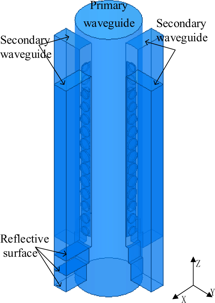
Figure 1: Structure of feed.
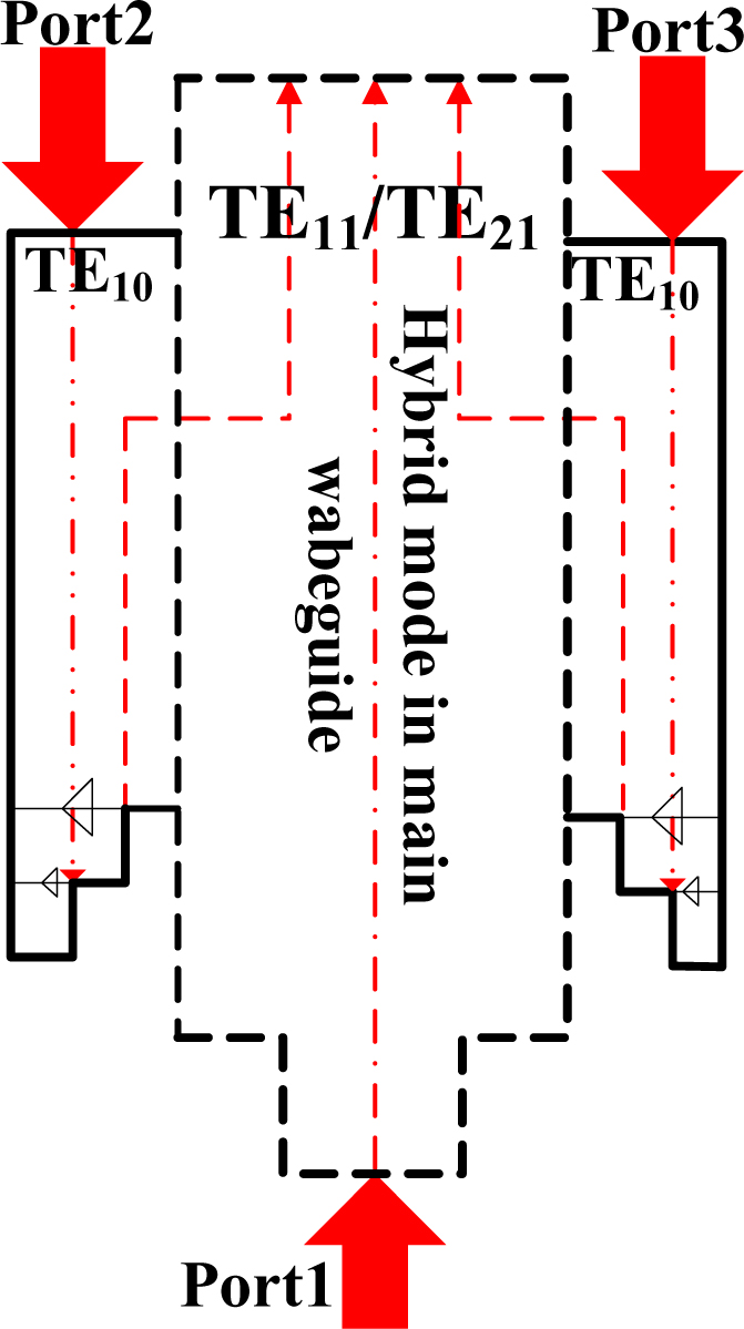
Figure 2: Workflow of EBS feed.
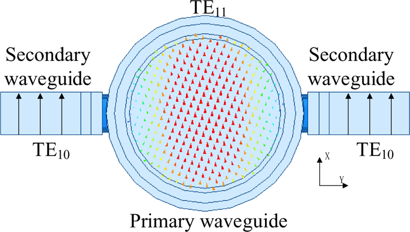
Figure 3: Schematic of fields in both main/secondary waveguide (TE).
Under the reciprocity theorem of transmission and reception, the feed can be considered as a transmission antenna. To generate phase differences for the purpose of shifting the phase center, a pair of coupling waveguides and primary waveguides can be utilized. The phase distributions of the TE mode and the TE mode along the Y-axis play a crucial role in achieving the desired phase center shifting. In Fig. 2, a pair of coupling waveguides and primary waveguides are applied to demonstrate how phase differences are generated to make phase center shifting.
When observing the phase distribution along the Y-axis for the TE mode (shown in Fig. 3), there is no difference in phase along the Y-axis. On the other hand, when observing the phase distribution along the Y-axis for the TE mode (shown in Fig. 4), it becomes apparent that the phase is exactly opposite along the Y-axis. This characteristic of the TE mode plays a critical role in achieving the necessary phase differences required for the phase center shifting. By using these phase differences in the TE mode, the phase center shifting can be effectively realized.
In primary waveguide, the mode is mixed with TE and TE which are from port 1 and port 2/3, respectively. In this hybrid mode, the direction of the beam corresponds to the phase center. Therefore, if the phase center squints, the beam direction will also squint proportionally.
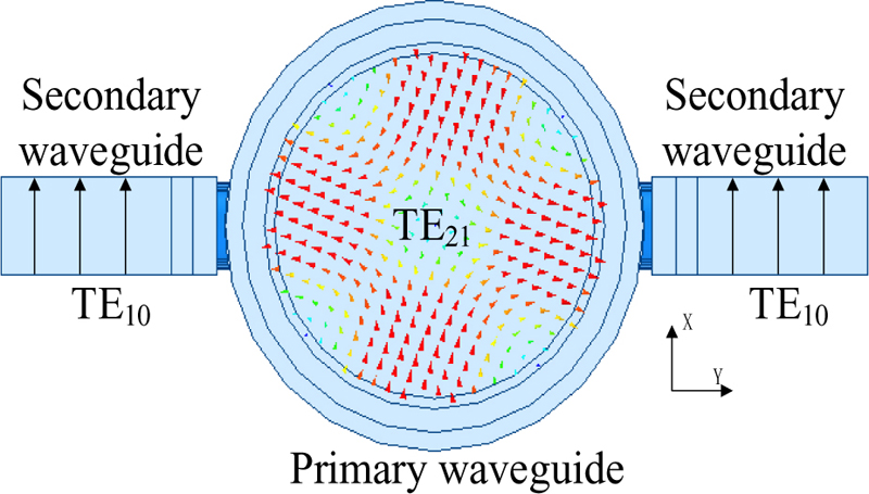
Figure 4: Schematic of fields in both main/secondary waveguide (TE).
To control the phase differences between the TE modes in a pair of secondary coupling waveguides, different reflective surfaces are applied in each secondary waveguide. By adjusting the reflective surfaces, the phase distribution over the aperture can be adjusted to achieve desired phase center. After applying diodes in different reflective surfaces, the position of these reflective surfaces is reconfigurable, allowing for precise control of the phase differences. When the phase difference between the two secondary waveguides is 0, the phase center over the aperture will be located at its geometric center, and the TE modes from both secondary coupling waveguides will cancel each other out. However, when the phase difference is 180, the phase center will be located at the maximum offset position, thus generating the desired beam squinting.
In 2010, Satish K. Sharma and Ashish Tuteja designed a 3-mode feed using slot coupling. This feed achieved a gain of about 14 dBi at the center frequency of 7.73 GHz, a maximum beam shift of 24 in the azimuth and elevation direction, and a bandwidth of about 7.48-8 GHz for S-10 dB. However, in this work, a porous coupling is applied to replace the slot coupling. In this way, we could improve the isolation between each port and accuracy of phase center control. S-parameters are shown in Fig. 5.
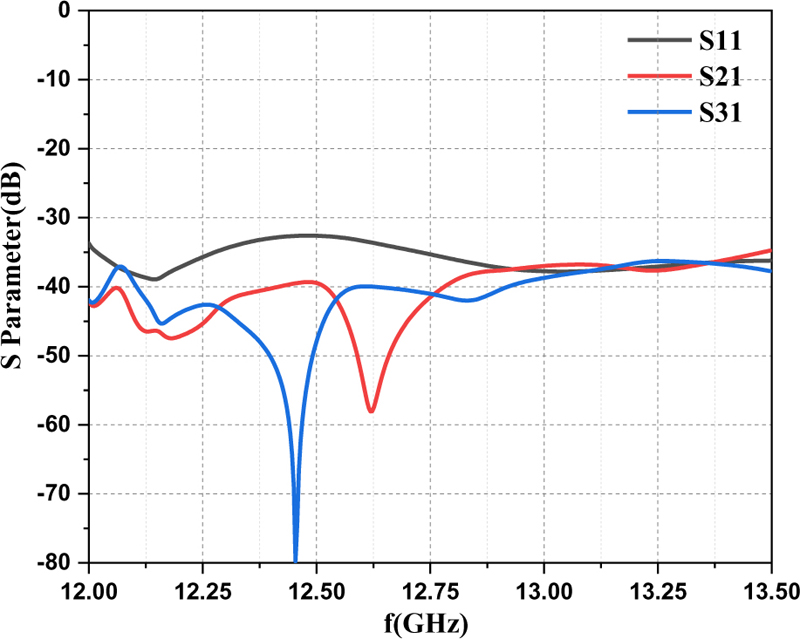
Figure 5: Simulated S-parameter.
From Fig. 5 we observed that significant improvements have been achieved compared to the 3-mode feed developed by Satish K. Sharma in terms of S and port isolation. The S parameter being less than -20 dB over the bandwidth range indicates good matching, while the port isolation exceeding 45 dB around the center frequency of 12.5 GHz demonstrates strong suppression of the reflected TE mode. The port isolation improvement is attributed to the strong coupling utilized in this antenna.
For a comprehensive analysis of the hybrid mode in the transmission antenna, it is essential to quantitatively analyse the magnitudes in both coupling waveguides. By ensuring that the magnitudes in both coupling waveguides are the same, the beam direction and gain can be calculated separately for different hybrid mode ratios. The beam direction and gain are calculated separately in different hybrid mode ratios (shown in Fig. 6). By systematically evaluating the influence of varying hybrid mode ratios on these parameters, a thorough understanding of the antenna’s performance under different configurations can be obtained.
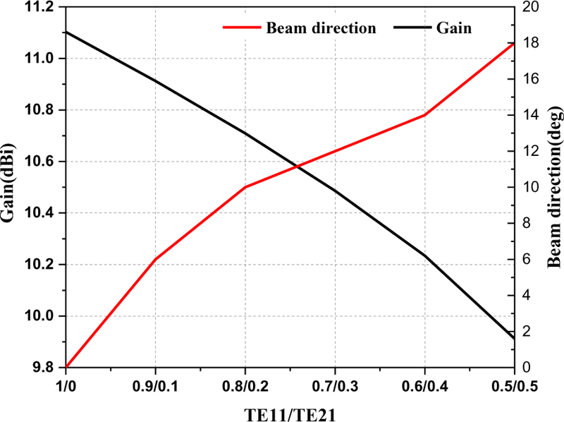
Figure 6: Gain and beam direction.
As shown in Fig. 6, there is a direct relationship between the difference in mode ratio, beam direction, and gain. Specifically, the greater the difference in mode ratio, the greater the beam direction and the greater the drop in gain. This accentuates the importance of selecting an appropriate mode ratio to achieve a desirable balance between beam direction and gain. Since the beam direction corresponds to the phase center, when the beam direction is at its maximum degree, the phase center shifts to the maximum position. Therefore, it is critical to carefully consider the impact of different mode ratios on the phase center to avoid undesirable beam squinting.
In this work, in case the gain is too low, it is advisable to select a mode ratio of 6:4. Additionally, the simulated radiation patterns in different phases are shown in Figs. 7–9 in the horizontal plane.
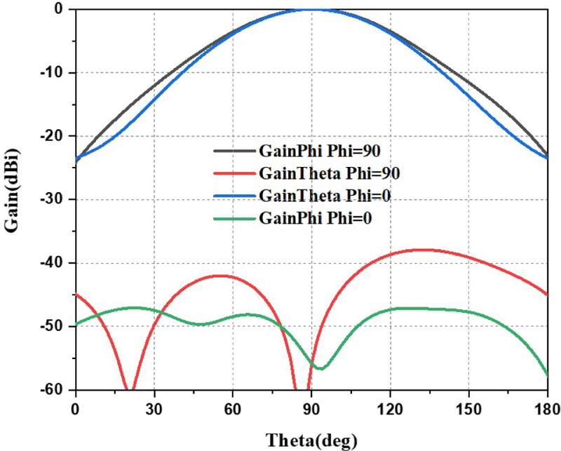
Figure 7: Simulated radiation pattern in 0 phase difference.
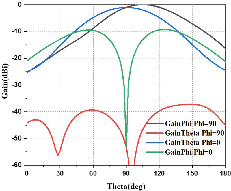
Figure 8: Simulated radiation pattern in 180 phase difference.
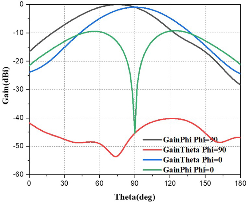
Figure 9: Simulated radiation pattern in -180 phase difference.
Figure 7 shows the results of 0 phase difference in both E and H plane with cross-polarization. It can be observed from Fig. 7, E plane and H are equalized well. Figure 8 also shows the results of 180 phase difference in E and H plane with cross-polarization. The main beam in H plane is 14. Figure 9 shows the results of -180 phase difference in E and H plane with cross-polarization. The main beam in H plane is .
The cross-polarization isolation is greater than 40 dB in all three radiation patterns shown in Figs. 7–9, indicating that cross-polarization has minimal influence on tracking accuracy.
Furthermore, it is evident from the results that by controlling the phase of the reflective reconfigurable EBS feed, electronic beam shifting within 14 can be achieved. However, to achieve a larger beam shift degree, a larger aperture may be needed, which could lead to a decrease in aperture efficiency.
Under the reciprocity theorem of transmission and reception, if the transmission antenna can achieve a certain angle of beam squinting, it can also receive signals within 14. Table 1 provides information on other phase differences that result in beam squinting.
Table 1: Phase difference and beam squinting
| Phase Difference | Beam Squinting | Phase Difference | Beam Squinting |
|---|---|---|---|
| 30 | 4 | 30 | 4 |
| 60 | 8 | 60 | 8 |
| 90 | 12 | 90 | 12 |
| 180 | 14 | 180 | 14 |
III. RESULTS AND EXPERIMENTAL VALIDATION OF REFLECTIVE RECONFIGURABLE EBS FEED
After the simulation, it is necessary to validate the performance of the reflective reconfigurable EBS feed. To accomplish this, the Voltage Standing Wave Ratio (VSWR) of the antenna is measured using a vector network analyzer. Additionally, the radiation patterns of the antenna at 180 phase differences are measured in a microwave measurement darkroom at Xi’an University of Electronic Science and Technology. The antenna far field measurement system used for this purpose was XD-2. For reference, a photograph of the reflective reconfigurable EBS feed is shown below. The photograph of the processed antenna and the measurement environment are shown in Figs. 10 and 11, respectively.
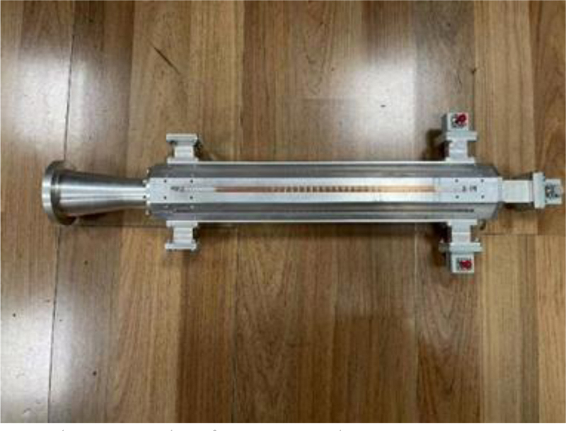
Figure 10: Photograph of processed antenna.
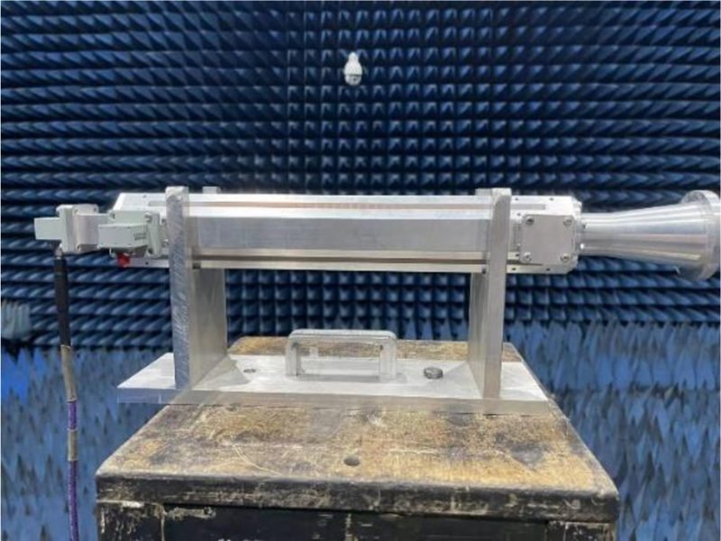
Figure 11: Photograph of measuring the processed antenna.
The results shown in Fig. 12 indicate that the S-parameter measurements of the feed are close to the simulation results. The reflection coefficient for port 1 (S) is less than -20 dB across the bandwidth. Moreover, the port isolation (S and S) is measured to be greater than -40 dB, indicating effective isolation between port 1 and port 2, as well as between port 1 and port 3. It is noted that the porous coupler has a positive impact on improving the port isolation, which is an important factor in ensuring minimal interference and efficient functioning of the feed. These results validated the effectiveness of the feed design and its ability to maintain good matching and isolation characteristics, as verified through the S-parameter measurements.
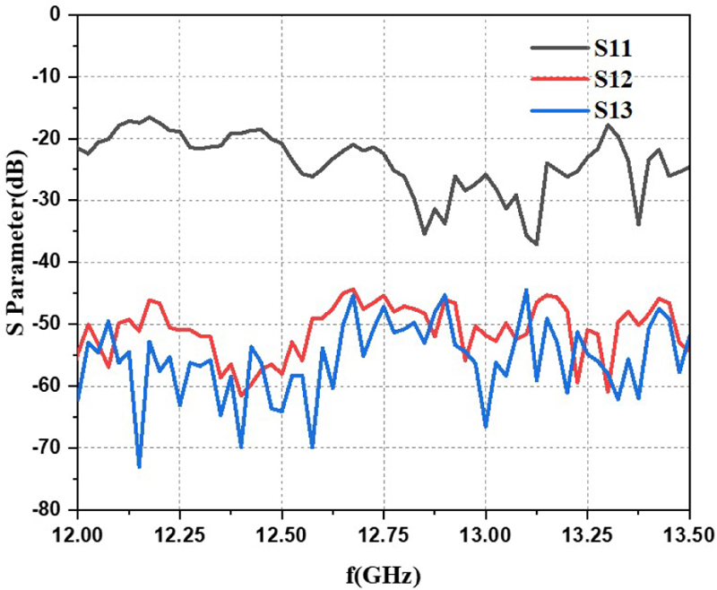
Figure 12: Measured S-parameter.
For the accuracy of the main and cross-polarization, phase center of both measure and measured antenna should be aligned. The measured radiation patterns of reflective reconfigurable EBS feed are shown in Figs. 13 and 14.
In Fig. 13, with a 180 phase difference, the results show the cross-polarization and beam squinting in both the E and H planes. The maximum beam squinting is 13. Similarly, Fig. 14 shows -180 phase difference results in both planes. Notably, the main beam is -13.
In this case, the beam squint is from -13 to 13 and the cross-polarization isolation is larger than 30 dB. Table 2 provides further details on the measured radiation patterns under various phase differences.
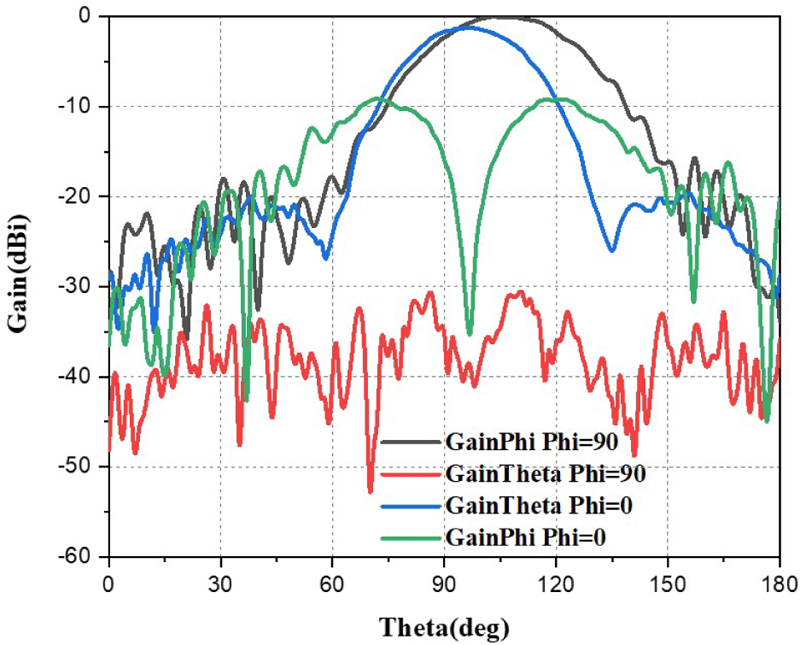
Figure 13: Measured radiation pattern in 180 phasedifference.
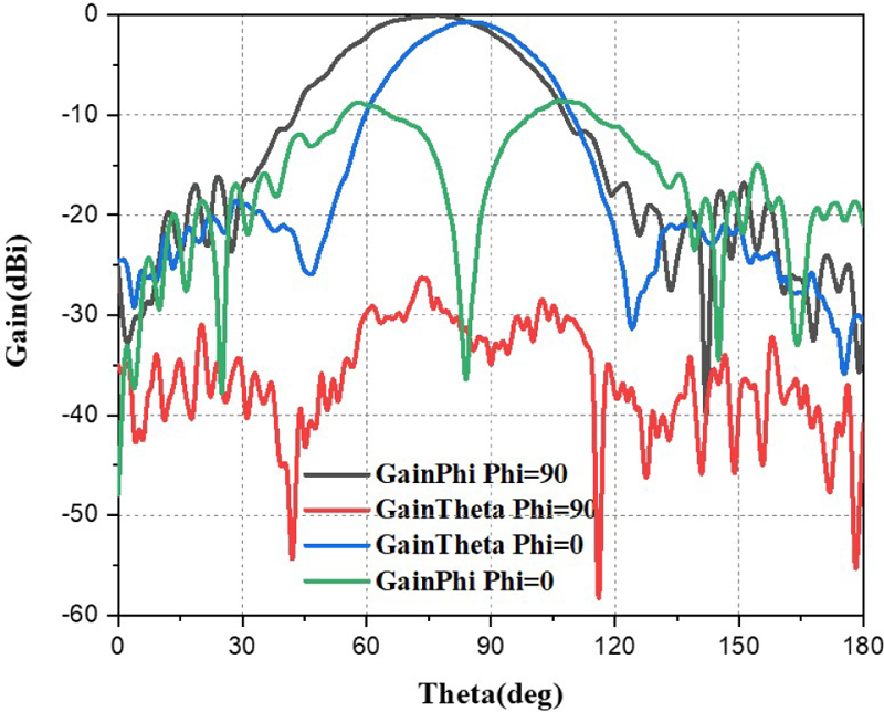
Figure 14: Measured radiation pattern in -180 phase difference.
Table 2: Experiment result of phase difference and beam squinting
| Phase Difference | Beam Squinting | Phase Difference | Beam Squinting |
|---|---|---|---|
| 30 | 3 | 30 | -3 |
| 60 | 6 | 60 | -6 |
| 90 | 9 | 90 | -9 |
| 180 | 13 | 180 | -13 |
Considering the measurement errors, when compared with the simulation results, the experiment results are close to simulation results. This agreement between the measured and simulated results further strengthens the dependability of the experimental results.
By validating the experiment against the simulation, it verifies that the antenna’s performance matches the anticipated performance. This enhances our confidence in the reliability and accuracy of the experimentally obtained radiation patterns and the overall performance evaluation of the reflective reconfigurable EBS feed.
IV. CONCLUSION
In this paper, reflective reconfigurable EBS feed is proposed. The application of porous coupling improves the port isolation, demonstrating an effective way to improve the antenna’s performance. Furthermore, the separation of the primary and secondary waveguides enables control of the phase and manipulation of the main beam direction.
To ensure accurate phase control in the secondary waveguide, minimizing the leakage from the primary waveguide is crucial. As such, the authors have simplified the structure by removing corrugations or chokes and applying the porous coupler to increase portisolation.
This EBS feed could achieve beam squinting in horizontal plane within 14 without reflector and higher aperture efficiency (85%). By adjusting reflective surface with diodes, the reaction time is reduced, enabling faster adjustments to meet changing requirements. Moreover, the application of the secondary waveguide located along the main waveguide enables miniaturization of the feed, making it more compact and easier to integrate into various systems.
Overall, the proposed reflective reconfigurable EBS feed offers several advantages over traditional designs, including improved port isolation, accurate phase control, and high aperture efficiency. These characteristics make it a valuable addition to satellite communication that require accurate tracking and rapidresponse.
ACKNOWLEDGMENT
This work is supported by the National Natural Science Foundation of China under General Program (62271364), Key Research and Development Program of Shaanxi (Program No. 2023-GHZD-45), Fundamental Research Funds for the Central Universities (ZYTS23145).
REFERENCES
[1] G. J. Hawkins, D. J. Edwards, and J. P. McGeehan, “Tracking system for satellite communications,” IEE Proceedings, vol. 135, no. 5, pp. 393-407, Oct. 1988.
[2] G. J. Hawkins and D. J. Edwards, “Operational analysis of electronic tracking schemes,” IEE Proceedings, vol. 136, no. 3, pp. 181-188, June 1989.
[3] P. B. Kenington, D. J. Edwards, and J. P. McGeehan, “Receivers for an electronic ‘beam-squint’ tracking system,” IEEE Proceedings. Part I: Communications, Speech and Vision, vol. 136, no. 4, pp. 305-311, Aug. 1989.
[4] L. Solymar, “Waveguide tapers, transitions and couplers,” Electronics and Power, vol. 26, no. 10, p. 823, Oct. 1980.
[5] J. S. Cook and R. Lowell, “The autotrack system,” The Bell System Tech, vol. 42, no. 4, pp. 1283-1307, July 1963.
[6] R. E. Collin, Field Theory of Guided Waves. New York: Wiley, 1991.
[7] N. Marcuvitz, Waveguide Handbook. Stevenage: Institution of Electrical Engineers, 1986.
[8] Jin Au Kong, Electromagnetic Wave Theory. Cambridge, MA: EMW Publishing, 2008.
[9] Y. Rahmat-Samii, The Handbook of Antenna Design: Volume I. Antennas and Propagation Society Newsletter, IEEE, 1983.
[10] L. Zhu and N. Liu, “Multimode resonator technique in antennas: A review,” Electromagnetic Science, vol. 1, no. 1, pp. 1-17, 2023.
[11] S. E. Miller “Coupled wave theory and waveguide applications,” Bell System Technical Journal, vol. 33, no. 3, pp. 661-719, May 1954.
[12] S. E. Miller, “On solutions for two waves with periodic coupling,” Bell System Technical Journal, vol. 47, no. 8, pp. 1801-1822, Oct. 1968.
[13] Y. H. Choung, K. R. Goudey, and L. G. Bryans, Theory and design of a Ku-band TE/sub21/-mode coupler, IEEE Transactions on Microwave Theory and Techniques, vol. 30, no. 11, pp. 1862-1866, Nov. 1982.
[14] E. H. Lenzing and H. F. Lenzing, “Characteristics of the TE mode in circular apertures as used for satellite tracking,” IEEE Transactions on Aerospace and Electronic Systems, vol. 37, no. 3, pp. 1113-1117, July 2001.
[15] S. K. Sharma and A. Tuteja, “Investigations on a triple mode waveguide horn capable of providing scanned radiation patterns,” 2010 IEEE Antennas and Propagation Society International Symposium, Toronto, July 2010.
BIOGRAPHIES

Bo-Wen Zhang was born in Xi’an, China. He received the B.S. degree in electronic information Technology from Xidian University, Xi’an, China, in 2012. After that he received the M.E. in science and engineering from Toyo University, Tokyo, Japan. Since 2019, he is currently pursuing the Ph.D. degree from Xidian University. His current research interests include corrugated horn antenna, beam-shaped array antenna and metamaterial applications in antenna.

Liang-Xin Xia was born in Anhui, China, in February 1997. He received the B.S. degree in electronic information Technology from Xidian University, Xi’an, China, in 2019, where he is currently pursuing the Ph.D. degree. His current research interests include Fabry-Perot cavity antenna, wide-beam antenna and beam-shaped array antenna.

Neng-Wu Liu (Senior Member, IEEE) was born in Changde, China. He received the B.S. and M.E. degrees in electrical engineering from Xidian University, Xi’an, China, in 2012 and 2015, respectively, and the Ph.D. degree from the University of Macau, Macau, in 2017, Since 2018, he has been an Associate Professor with Xidian University. From 2019 to 2021, he was the UM Macao Post-Doctoral Research Fellow under the UM Macao Talent Program. His current research interests include designs of antenna theory, low-profile antenna, multimode antenna, wideband antenna, patch antenna, dielectric resonator antenna, circularly polarized antennas, filtering antenna, slot antenna, and phased array. Dr. Liu was a recipient of several academic awards, which includes the Best Student Paper Award in the 17th IEEE Macau/HK AP/MTT Postgraduate Conference and the Best Student Paper Award in 2017 National Conference on Antennas. He was also a recipient of the Outstanding Reviewer Award from the IEEE Transactions on Antennas and Propagation in 2020, 2021, and 2022; and the 2022 Macao Natural Science Awards (Second Prize) from the Science and Technology Development Fund (FDCT), Macau. He serves as an Associate Editor for IET Microwaves, Antennas and Propagation, IEEE Access, and Electronics Letters (IET).

Guang Fu received the B.S. and M.S. degrees in electromagnetic field and microwave technology from Xidian University, Xi’an, China, in 1984 and 1991, respectively.
He became a Professor with Xidian University in 2001. His current research interests include theory and engineering of antenna and antenna array.
ACES JOURNAL, Vol. 39, No. 1, 39–45
doi: 10.13052/2024.ACES.J.390106
© 2024 River Publishers