Wideband Center-fed Stacked Patch Circularly Polarized Antenna used in Phased Array
Jiaxin Wang, Xiao Liu, Pengfei Zhang, Zheng Xu, Anqi Li, Zhengtian Chen, and Jin Fan
1Aerospace Information Research Institute
Chinese Academy of Sciences, Beijing, 100190, China
2School of Electronic, Electrical and Communication Engineering
University of Chinese Academy of Sciences, Beijing, 100190, China
3Beijing Institute of Control and Electronic Technology
Beijing, 100074, China
liuxiao@aircas.ac.cn
Submitted On: September 30, 2023; Accepted On: October 8, 2023
ABSTRACT
A center-fed circularly polarized stacked patch antenna (CF-CPSPA) with enhanced axial-ratio (AR) bandwidth is proposed in this paper. The antenna is composed of two microstrip patches, the lower patch consists of a circular pad, an elliptical-ring, and two branch lines connecting them, which is used to realize the center-fed condition, and the upper patch is an elliptical patch to achieve the wide band performance. Firstly, two center-fed linearly polarized stacked patch antennas with wide band are designed, one mode radiated with x polarization, and the other generates y polarized radiation. Next, the orthogonal modes of two linearly polarized antennas are combined together by a specific design. Finally, the approximate equal amplitude and quadrature phase difference of the introduced modes are achieved in the operating frequency band with proper parameters analysis. And the impedance bandwidth and 3dB AR bandwidth is improved to 30.4% and 16.5%.
Keywords: center-fed, stacked patch, unit in phased array, wideband circularly polarized antenna.
I. INTRODUCTION
Circularly polarized (CP) antennas have been widely used in modern wireless communication systems due to the improved immunity to multipath interferences, polarization mismatch losses, and Faraday rotation effects [1–4]. Among the CP antennas, microstrip patch antennas are preferred because of the advantages of low profile, low cost, and easy integration [1].
CP patch antennas can be designed by a multi-fed technique or a single-fed technique [1]. The former can achieve a better axial ratio (AR) bandwidth compared with a single-fed antenna. However, the complicated feeding networks limit their applications in phased arrays [5–9] when the unit spacing is restricted. For single-fed CP patch antennas, the AR bandwidth is generally narrow, and several methods have been proposed to enhanced the AR bandwidth, such as using thick substrates with low permittivity to lower the high Q-factor [9], or using aperture coupling or some another coupling way to feed the patch antenna [10–12]. In [9], an approximately 12% 3 dB AR bandwidth was gained by using a foam substrate with thickness of 0.2.
Another way to enhance the AR bandwidth is to introduce multiple pairs of orthogonal modes, such as stacked patches. Currently, various stacked patch antennas have been proposed [13–21]. The stacked structures of metasurface and patch radiators provide an improved CP performance [22–24]. Several orthogonal linearly polarized (LP) modes are designed in [25, 26] with equal magnitude and quadrature phase difference. In [26], a stacked U-slot patch antenna is designed to generate five LP modes and four AR minima poles, and the 3 dB AR bandwidth is 55%. However, the planar size of this design limits its application in phased arrays.
In CP phased arrays, a sequential rotation is generally applied to suppress the cross-polarization [27]. To improve the scanning performance in the diagonal plane of the array, a secondary sequential rotation or a random sequential rotation is employed [28, 29]. Therefore, the center-fed CP antennas are significantly required in rotation arrays because the position of the feeding port will be unchanged when the element is rotated. This characteristic significantly simplifies the feeding structure from the transmit-receive (TR) modules to the antenna elements in the millimeter-wave phased arrays. However, the center-fed CP patch antennas were rarely investigated in the past. Some center-fed CP patch antennas are proposed in [30, 31] with narrow AR bandwidths.
In this paper, a wide band CP stacked patch antenna fed by a coaxial probe located in the center of the lower patch is proposed. Firstly, two center-fed linearly polarized stacked patch antennas are designed. One generates two resonance modes in the x direction, and the other generates two resonance modes at higher frequencies in the y direction. Then, an elliptical design is applied to combine the orthogonal modes of two linearly polarized antennas together. Finally, with proper parameter analysis, the approximately equal magnitude and quadrature phase of the introduced split orthogonal modes are achieved in the band of interest. Compared with the center-fed patch antennas, the AR bandwidth of the proposed antenna is enhanced by an additional AR minima pole. The simulated and measured results are found in good agreement with each other, demonstrating that a -10 dB bandwidth of 30.4% and a 3 dB AR bandwidth of 16.5% are achieved. The final results indicate that this design is a good candidate for millimeter-wave AiP phased arrays.
This paper is organized as follows: Section II introduces the configuration, working mechanism and design process, and parametric studies of the proposed antenna. Section III gives the simulation and measurement results of the proposed antenna. The last section is a brief summary.
II. CENTER-FED CIRCULARLY POLARIZED STACKED PATCH ANTENNA
A. Configuration
The configuration of the proposed center-fed circularly polarized stacked patch antenna (CF-CPSPA) is shown in Fig. 1. It consists of two TSM-DS3 dielectric substrates (, ) with thickness of and , and two microstrip patches placed on them, respectively. The two substrates are bonded by FR28 material (, ) with thickness of . The size of the element is . The proposed antenna is fed by a coaxial probe located in the center of the lower patch. Moreover, a substrate integrated waveguide (SIW) back cavity based on the metalized vias is applied to suppress the propagation of surface waves and improve the scanning performance [34, 35], as shown in Fig. 1 (a).
The lower patch consists of a circular pad, an elliptical ring, and two branch lines connecting them as shown in Fig. 1 (b). The outer major radius and outer minor radius of the elliptical ring are and , and the inner radius is . Also, the major axis is along the x axis, the two branch lines are at an angle of and relative to plane. The upper patch is an elliptical patch whose direction of the major axis is consistent with that of the lower elliptical ring, as shown in Fig. 1 (c); the major radius and minor radius are and .

Figure 1: Configuration of the proposed center-fed circularly polarized stacked patch antenna: (a) Perspective view, (b) lower patch, and (c) upper patch (, , , , , , , , , , , , , , , , all in millimetres).
B. Working mechanism and design process
To illustrate the working mechanism of the proposed CF-CPSPA, four antennas with different configuration, named Ant. 1, Ant. 2, Ant. 3, and Ant. 4, are simulated and analyzed. The lower and upper patches of the four antennas are shown in Fig. 2, Ant. 1 and Ant. 2 are both linearly polarized, the upper and lower patches are circular, and the dimensional parameters are different. The directions of the two branch lines in the lower patch are orthogonal to each other. Ant. 3 and Ant. 4 are the proposed antenna structure in this paper. For Ant. 3, the parameters in xoz plane are the same as those of Ant. 1, and the parameters in yoz plane are the same as those of Ant. 2, and and are set as . Ant. 4 has the same parameters as listed in Fig. 1. Based on the studies of the four antennas, the design guidelines and methodology are summarized as follows. ( is the center operating frequency)
1) Design of Ant. 1 and Ant. 2.
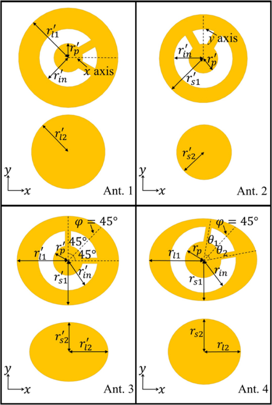
Figure 2: Lower and upper patches of the four antennas , , all in millimetres).
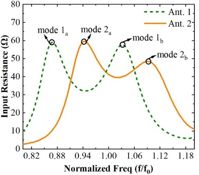
Figure 3: Simulated input resistance of Ant. 1 and Ant. 2.
Figure 3 exhibits the simulated input resistance of Ant. 1 and Ant. 2. For Ant. 1, two resonance modes, mode and mode , are generated from the stacked patches. The initial parameters of the annular-ring patch can be calculated according to the formula given in [32], and the design of stacked patch antennas is referred to in [33]. As the centerline of the two branch lines in the lower patch of Ant. 1 is along the x axis, the polarization of Ant. 1 is along the x direction. To further understand the two resonance modes, Fig. 4 displays the E-field distributions in the xoz plane of the two modes of Ant. 1. The E-field of mode is concentrated between the lower patch and the cavity, while for mode , the coupling between the lower and upper patches is significantly enhanced. As for Ant. 2, two resonance modes, mode and mode , are generated at higher frequencies due to the smaller dimensional parameters. Moreover, the centerline of the two branch lines in the lower patch of Ant. 2 is along the y axis; therefore, the polarization of Ant. 2 is along the y direction, which means mode and mode are orthogonal to mode and mode .
2) Design of Ant. 3 with an elliptical patch.
Ant. 3 introduces mode and mode by setting the parameters in the xoz plane the same as those of Ant. 1, and introduce mode and mode by setting the parameters in the yoz plane the same as those of Ant. 2. Meanwhile, the variations of the parameters in the yoz plane affect mode and mode slightly, and the variations of the parameters in the xoz plane affect mode and mode slightly. Therefore, the operating frequency of the orthogonal mode can be adjusted separately. The two branch lines of the lower patch of Ant. 3 are reset along the x axis and y axis, respectively, to excite the introduced orthogonal modes. Figure 5 shows the magnitude of far-field broadside and components of Ant. 1, Ant. 2, and Ant. 3, and agreement of the working frequencies can be observed. The differences in the magnitude of and of the three antennas result from the coupling between modes. As shown in Fig. 6, there are two AR minima poles satisfying AR 3dB, and if these two minima poles are close enough to each other, a wide 3dB AR bandwidth will be generated.
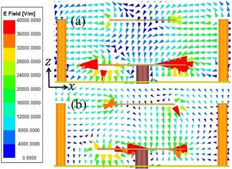
Figure 4: Simulated E-field distributions in xoz plane of (a) mode and (b) mode .
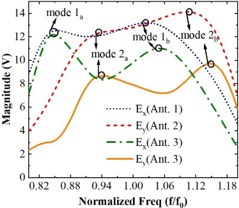
Figure 5: Simulated magnitude of far-field broadside and components of Ant. 1, Ant. 2, and Ant. 3.
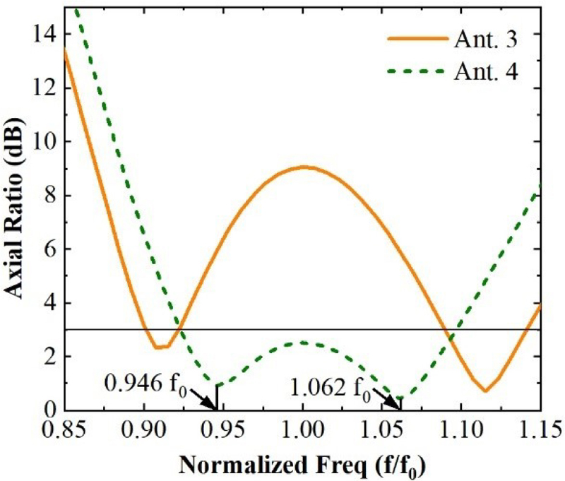
Figure 6: Simulated boresight AR of Ant. 3 and Ant. 4.
3) Tune the parameters to optimize the CP performance of Ant. 3.
To achieve approximately equal magnitude and quadrature phase difference of the orthogonal modes in the operating frequency band, the dimensional parameters of Ant. 3 need to be optimized. The critical parameters included the outer major radius of the lower patch (), the ratio of to (), the angle of the branch lines relative to the plane at (, ), and the major radius and minor radius of the upper elliptical patch (, ) is slightly tuned. Finally, Ant. 4 is obtained, the simulated AR result is plotted in Fig. 6, showing an improved CP performance compared with Ant. 3, and a 3 dB AR bandwidth of 17.3% is realized.
Besides, Fig. 7 demonstrates the surface currents on the lower and upper patches of Ant. 4 varying with time. Whether at 0.946 or 1.062, the surface currents on the upper and lower patches are both along the x direction when t = 0, and the surface currents on the upper and lower patches are both along the y direction when t = T/4, meeting the CP wave generation condition. The difference is that the surface current on the upper patch at 1.062 is slightly stronger than that at 0.946, which is consistent with the coupling of the upper and lower patches being enhanced at higher frequencies, as displayed in Fig. 4.
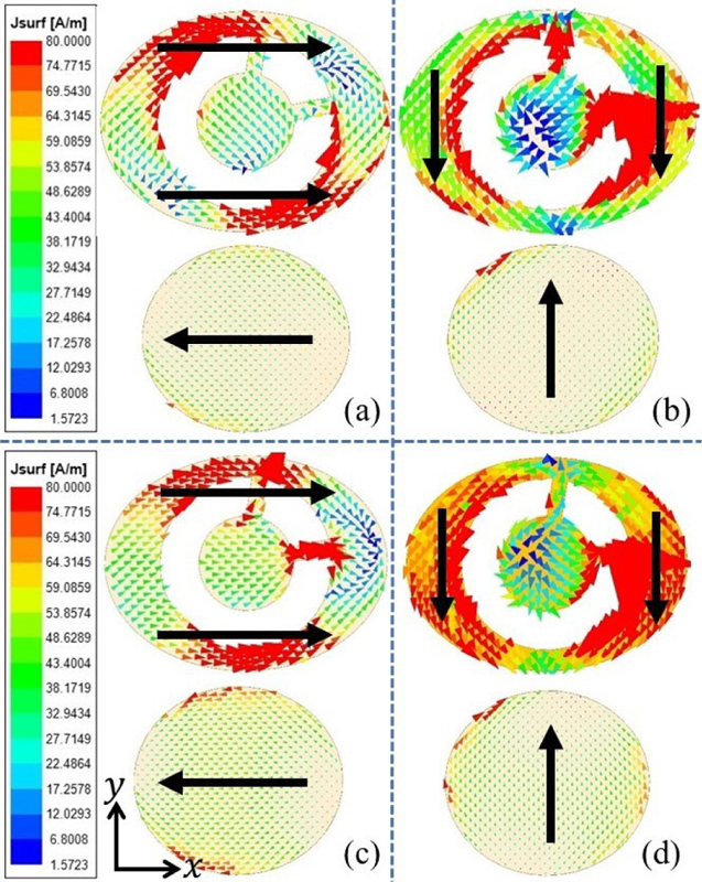
Figure 7: Simulated surface currents on the lower and upper patches of Ant. 4: (a) When t = 0 at 0.946, (b) when t = T/4 at 0.946, (c) when t = 0 at 1.062, and (d) when t = T/4 at 1.062, where T is the period of time.
C. Effect of parameters on the far-field broadside and components
To quantitatively investigate the influence of the dimensional parameters on the CP performance, the effects of some critical parameters on the far-field broadside and components of the proposed CF-CPSPA are studied. Compared with AR, and components can reveal the CP performance more essentially and visibly. In this paper, to assess the and components, the parameter “rE” in HFSS software is selected, which eliminates the effect of distance; in other words, the unit of “rE” is “V”.
Figure 8 shows the effects of some critical parameters on the magnitude or the phase difference of and components of the proposed CF-CPSPA, including the ratio of to (), the angle of the branch lines relative to the plane at (, ), and the major radius and minor radius of the upper elliptical patch (, ).
As shown in Fig. 6 (a), mainly affects the phase difference of and components, and a phase difference of about in the operating frequency band can be achieved with a proper value of . controls the ratio of to , which splits the two pairs of degenerate resonance modes. Therefore, is the most important parameter for the CP performance and should be tuned first.
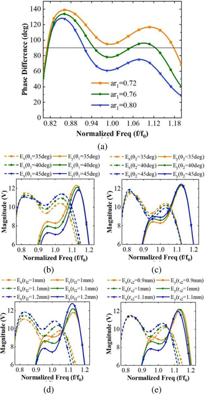
Figure 8: Simulated results of the magnitude or phase difference of far-field broadside and components under different parameters: (a) (b) (c) , (d) and (e) .
Figures 8 (b) and (c) exhibit the magnitude of and components at different values of and . It indicates that when line 1 is along the major axis of the elliptical ring, i.e., , the two resonances of are the most strongly excited, and as reduces, both of the ring, i.e., , the two resonances of are the most strongly excited, and as reduces, both of the lower and upper resonances of decrease, while the two resonances of increase. The effect of is just the opposite but weaker than that of . The variation presents a principle that when the coupling to one mode increases, the coupling to the other mode at the same frequency will be reduced. This principle also works in the studies of other parameters.
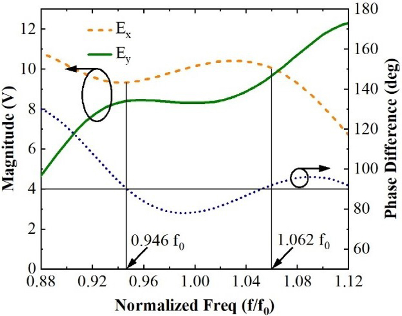
Figure 9: Phase difference and magnitude of far-field broadside and components of the proposed CF-CPSPA.
As can be seen from Figs. 8 (d) and (e), when increases, the magnitude of increased, while the magnitude of decreased at the lower frequency and increased at higher frequency. As increases, the lower resonance of decreases, but the upper resonance does not increase due to the increase of high input resistance and the worsened matching at the upper resonant frequency.
The effects of some other parameters are not discussed in detail. When increases, the resonant frequencies decrease and get closer. Keeping the difference of and fixed, the frequencies of the two resonances vary with . As and increase, the overall input resistance increases.
III. SIMULATED AND MEASURED RESULTS
According to the design steps above, the optimized dimensional parameters of the proposed CF-CPSPA are given in Fig. 1. And the magnitude and phase difference of the far-field broadside and components of the final antenna element are plotted in Fig. 9. At the frequencies of 0.946 and 1.062, the magnitudes of the two orthogonal components are roughly equal and the phase difference is close to 90, indicating two AR minima poles, as shown in Fig. 6. To validate the simulated results, a prototype is fabricated and measured, as shown in Fig. 10, and the size of the substrates and the metal ground are enlarged for easier fixing. The reflection coefficients and AR are measured as shown in Fig. 11.
As shown in Fig. 11 (a), the measured and simulated AR responses are found in good agreement with each other, the simulated and measured 3 dB AR bandwidths are 0.923 - 1.096 (17.3%) and 0.942 - 1.107 (16.5%), verifying an enhanced wideband performance. The tolerable frequency offset is mainly due to the enlarged metal ground and inevitable measurement errors. Figure 11 (b) exhibits the simulated and measured reflection coefficients and realized broadside LHCP gains. A -10 dB bandwidth from 0.834 to 1.138 GHz (30.4%) is achieved, which is well consistent with the simulated result. Besides, the realized broadside LHCP gain are between 4.9 and 6.0 dBic in the 3 dB AR bandwidth. Figure 12 shows the simulated and measured results of the normalized RHCP and LHCP far-field radiation patterns in xoz and yoz planes, and a large angular beamwidth is observed. Note that, because of the enlarged metal ground, the forward radiation of the element increases, the measured gain is therefore slightly higher than the simulated gain, and the measured beamwidth is narrowed compared with the simulated results.
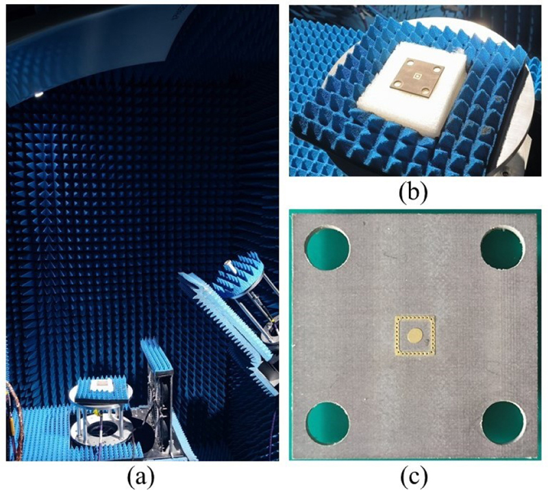
Figure 10: Photographs of (a) the test environment, (b) the CF-CPSPA on the test bench, and (c) the top view of the CF-CPSPA.
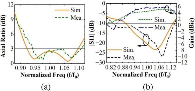
Figure 11: Simulated and measured results of the proposed CF-CPSPA: (a) Boresight AR and (b) and realized boresight LHCP gain.
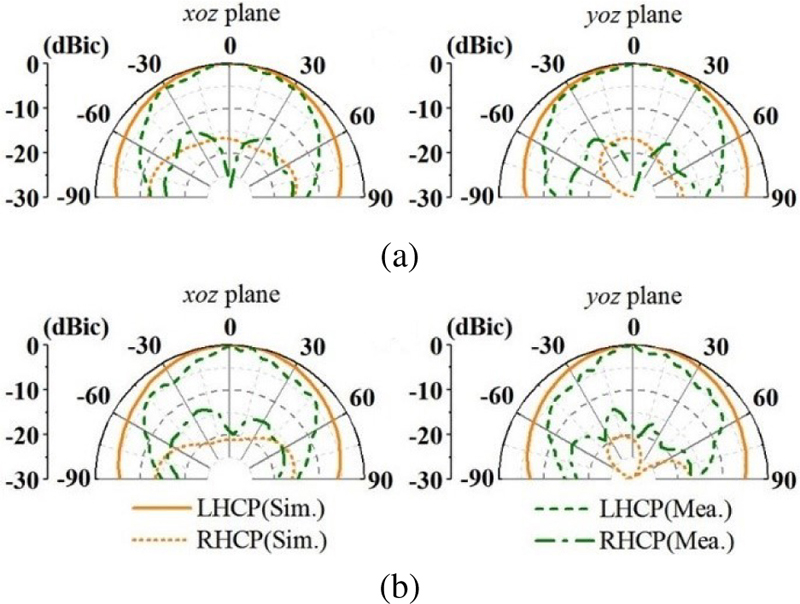
Figure 12: Simulated and measured normalized radiation patterns of the proposed CF-CPSPA at (a) 0.962 and (b) 1.038.
Table 1: Comparisons of different single-fed CP patch antennas
| Ref. | Size | IMBW | ARBW | Wideband Approaches | |
| [9] | 25.3 | 11.8 | Thick air substrate | ||
| 40 | 17.3 | Stack patches, air spacing | |||
| 25.8 VSWR | 13.5 | Stack patches, meandering strip | |||
| 34.7 | 20.1 | Stack patches, metasurface | |||
| 96.7 | 52.7 | Stack patches, penta-mode ( poles) | |||
| - | - | ||||
| Our Work | 30.4 | 16.5 | Y | Stack patches | |
| The free-space wavelength at the center operating frequency . IMBW: Impedance bandwidth, default is bandwidth. ARBW: AR bandwidth. CF: Whether the antenna is center-fed. | |||||
The measured performances of the proposed CF-CPSPA are tabulated in Table 1 and compared with other reported single-fed CP patch antennas. Compared with traditional CP stacked patch antennas [16, 19], our proposed CF-CPSPA has similar impedance bandwidth and AR bandwidth, Meanwhile, it has the characteristic of being center-fed. And compared with existing center-fed CP patch antennas [30], our proposed CF-CPSPA has much wider impedance bandwidth and AR bandwidth. Besides, the proposed CF-CPSPA is easy to design (compared with [26]) and meets the spacing requirement of the wide-angle scanning (comparedwith [24]).
IV. CONCLUSION
In this paper, a center-fed CP stacked patch antenna has been proposed to improve the AR bandwidth. By an elliptical patch design, the orthogonal linearly polarized modes are combined together in the proposed antenna. The working mechanism and design process have been illustrated, and the effect of antenna parameters on the far-field broadside and components has been investigated. Then, the proposed antenna is fabricated and measured. The simulated and measured results are consistent with each other, showing a -10 dB bandwidth of 30.4% and a 3 dB AR bandwidth of 16.5%. The final results indicate that the proposed antennas will be promising candidates for millimeter-wave AiP phased arrays.
REFERENCES
[1] S. Gao, Q. Luo, and F. Zhu, Circularly Polarized Antennas, Hoboken, NJ, USA: Wiley, Nov.2013.
[2] M. Z. Xiao, H. Liu, and Y. H. Cui, “Broadband circularly polarized antennas with improved gain,” Applied Computational Electromagnetics Society (ACES) Journal, vol. 34, no. 10, pp. 1514-1519, Oct. 2019.
[3] R. Ma and Q. Y. Feng, “Broadband CPW-fed circularly polarized square slot antenna for universal UHF RFID handheld reader,” Applied Computational Electromagnetics Society (ACES) Journal, vol. 36, no. 6, pp. 747-754, Nov. 2021.
[4] B. S. Qiu, Y. F. Xia, and Y. S. Li, “Gain-enhanced wideband circularly polarized antenna with a non-uniform metamaterial reflector,” Applied Computational Electromagnetics Society (ACES) Journal, vol. 37, no. 3, pp. 281-286, July 2022.
[5] S. D. Targonski and D. M. Pozar, “Design of wideband circularly polarized aperture-coupled microstrip antennas,” IEEE Trans. Antennas Propag., vol. 41, no. 2, pp. 214-220, Feb. 1993.
[6] L. Bian, Y.-X. Guo, L. C. Ong, and X.-Q. Shi, “Wideband circularly-polarized patch antenna,” IEEE Trans. Antennas Propag., vol. 54, no. 9, pp. 2682-2686, Sep. 2006.
[7] Y.-X. Guo, L. Bian, and X. Q. Shi, “Broadband circularly polarized annular-ring microstrip antenna,” IEEE Trans. Antennas Propag., vol. 57, no. 8, pp. 2474-2477, Aug. 2009.
[8] C.-F. Liang, Y.-P. Lyu, D. Chen, and C.-H. Cheng, “Wideband circularly polarized stacked patch antenna based on TM11 and TM10,” IEEE Trans. Antennas Propag., vol. 70, no. 4, pp. 2459-2467, Apr. 2022.
[9] S. S. Yang, K.-F. Lee, and A. A. Kishk, “Design and study of wideband single feed circularly polarized microstrip antennas,” Prog. Electromagn. Res., vol. 80, pp. 45-61, 2008.
[10] P. Sullivan and D. Schaubert, “Analysis of an aperture coupled microstrip antenna,” IEEE Trans. Antennas Propag., vol. 34, no. 8, pp. 977-984, Aug. 1986.
[11] J.-S. Row, “Design of aperture-coupled annular-ring microstrip antennas for circular polarization,” IEEE Trans. Antennas Propag., vol. 53, no. 5, pp. 1779-1784, May 2005.
[12] H. Al-Saedi, W. M. Abdel-Wahab, S. Gigoyan, R. Mittra, and S. Safavi-Naeini, “Ka-band antenna with high circular polarization purity and wide AR beamwidth,” IEEE Antennas Wireless Propag. Lett., vol. 17, no. 9, pp. 1697-1701, Sep. 2018.
[13] K. P. Nasimuddin, Esselle, and A. K. Verma, “Wideband circularly polarized stacked microstrip antennas,” IEEE Antennas Wireless Propag. Lett., vol. 6, pp. 21-24, 2007.
[14] Z.-X. Liu, L. Zhu, and X. Zhang, “A low-profile and high-gain CP patch antenna with improved AR bandwidth via perturbed ring resonator,” IEEE Antennas Wireless Propag. Lett., vol. 18, no. 2, pp. 397-401, Feb. 2019.
[15] S. Shekhawat, P. Sekra, D. Bhatnagar, V. K. Saxena, and J. S. Saini, “Stacked arrangement of rectangular microstrip patches for circularly polarized broadband performance,” IEEE Antennas Wireless Propag. Lett., vol. 9, pp. 910-913, 2010.
[16] K. L. Chung and A. S. Mohan, “A systematic design method to obtain broadband characteristics for singly-fed electromagnetically coupled patch antennas for circular polarization,” IEEE Trans. Antennas Propag., vol. 51, no. 12, pp. 3239-3248, Dec. 2003.
[17] N. Yan, K. Ma, and Y. Luo, “An SISL sequentially rotated feeding circularly polarized stacked patch antenna array,” IEEE Trans. Antennas Propag., vol. 68, no. 3, pp. 2060-2067, Mar. 2020.
[18] T.-N. Chang and J.-M. Lin, “Circularly polarized ring-patch antenna,” IEEE Antennas Wireless Propag. Lett., vol. 11, pp. 26-29, 2012.
[19] Z. Wang, S. Fang, S. Fu, and S. Jia, “Single-fed broadband circularly polarized stacked patch antenna with horizontally meandered strip for universal UHF RFID applications,” IEEE Trans. Microw. Theory Tech., vol. 59, no. 4, pp. 1066-1073, Apr. 2011.
[20] Q. W. Lin, H. Wong, X. Y. Zhang, and H. W. Lai, “Printed meandering probe-fed circularly polarized patch antenna with wide bandwidth,” IEEE Antennas Wireless Propag. Lett., vol. 13, pp. 654-657, 2014.
[21] W. Yang, J. Zhou, Z. Yu, and L. Li, “Single-fed low profile broadband circularly polarized stacked patch antenna,” IEEE Trans. Antennas Propag., vol. 62, no. 10, pp. 5406-5410, Oct. 2014.
[22] S. X. Ta and I. Park, “Low-profile broadband circularly polarized patch antenna using metasurface,” IEEE Trans. Antennas Propag., vol. 63, no. 12, pp. 5929-5934, Dec. 2015.
[23] K. E. Kedze, H. Wang, and I. Park, “A metasurface-based wide-bandwidth and high-gain circularly polarized patch antenna,” IEEE Trans. Antennas Propag., vol. 70, no. 1, pp. 732-737, Jan. 2022.
[24] N. Hussain, M.-J. Jeong, A. Abbas, T.-J. Kim, and N. Kim, “A metasurface-based low-profile wideband circularly polarized patch antenna for 5G millimeter-wave systems,” IEEE Access, vol. 8, pp. 22127-22135, 2020.
[25] N.-W. Liu, L. Zhu, Z.-X. Liu, G. Fu, and Y. Liu, “Design approach of a single circularly polarized patch antenna with enhanced AR-bandwidth under triple-mode resonance,” IEEE Trans. Antennas Propag., vol. 68, no. 8, pp. 5827-5834, Aug.2020.
[26] J. Zeng, Z. Zhang, F. H. Lin, and F. Guan, “Penta-mode ultrawideband circularly polarized stacked patch antennas using characteristic mode analysis,” IEEE Trans. Antennas Propag., vol. 70, no. 10, pp. 9051-9060, Oct. 2022.
[27] J. Huang, “A technique for an array to generate circular polarization with linearly polarized elements,” IEEE Trans. Antennas Propag., vol. 34, no. 9, pp. 1113-1124, Sep. 1986.
[28] A. B. Smolders and H. J. Visser, “Low side-lobe circularly-polarized phased arrays using a random sequential rotation technique,” IEEE Trans. Antennas Propag., vol. 62, no. 12, pp. 6476-6481, Dec. 2014.
[29] J. Wen, Z. H. Huang, Y. L. Yao, Y. Zhang, J. H. Wang, L. P. Hou, and Y. H. Liang, “Cross polarization suppression of sequentially rotated circularly polarized phased array,” Telecommunication Engineering, vol. 61, no. 8, pp. 956-964, 2021.
[30] L. L. Xue, W. T. Fang, J. Xu, C. Ji, and F. F. Qu, “Design of a circularly polarized antenna using central feed,” Radio Engineering, vol. 51, no. 4, pp. 308-312, 2021.
[31] H. K. Kan and R. B. Waterhouse, “Low cross-polarised patch antenna with single feed,” Electronics Letters, vol. 43, no. 2007, pp. 9-10, 2007.
[32] X. Chen, G. Fu, S.-X. Gong, Y.-L. Yan, and W. Zhao, “Circularly polarized stacked annular-ring microstrip antenna with integrated feeding network for UHF RFID readers,” IEEE Antennas Wireless Propag. Lett., vol. 9, pp. 542-545, 2010.
[33] F. Croq and D. M. Pozar, “Millimeter-wave design of wide-band aperture-coupled stacked microstrip antennas,” IEEE Trans. Antennas Propag., vol. 39, no. 12, pp. 1770-1776, Dec. 1991.
[34] M. H. Awida, A. H. Kamel, and A. E. Fathy, “Analysis and design of wide-scan angle wide-band phased arrays of substrate-integrated cavity-backed patches,” IEEE Trans. Antennas Propag., vol. 61, no. 6, pp. 3034-3041, June 2013.
[35] S. E. Valavan, D. Tran, A. G. Yarovoy, and A. G. Roederer, “Planar dual-band wide-scan phased array in x-band,” IEEE Trans. Antennas Propag., vol. 62, no. 10, pp. 5370-5375, Oct.2014.
BIOGRAPHIES

Jiaxin Wang was born in Benxi, Liaoning. He received the B.S. degree in electronical information science and technology from Tsinghua University, Beijing, China, in 2021. He is currently working toward the M.S. degree in electromagnetic field and microwave technology with the School of Electronic, Electrical and Communication Engineering, University of Chinese Academy of Sciences, Beijing, China.
His research interests include antenna theory and design, especially in circularly polarized antennas.

Xiao Liu received the M.S. degree from Beijing Institute of Technology, Beijing, China, in 2009 and the Ph.D. degree from the University of Chinese Academy of Sciences, Beijing, China, in 2023. Xiao Liu has been involved in the research and engineering implementation of active phased array antennas and integrated process technology.

Pengfei Zhang received the B.Eng. degree and Ph.D. degree from the University of Electronic Science and Technology of China, Chengdu, China, in 2015 and 2021. Since 2022, he has been a postdoctoral and research assistant in Aerospace Information Research Institute, Chinese Academy of Sciences, Beijing, China. His research interests include planer leaky-wave antennas and active phased array antennas.

Zheng Xu received the B.S. degree and M.S. degree from Beijing Institute of Technology, Beijing, China, in 2006 and 2008. He received the Ph.D. degree from University of Chinese Academy of Sciences, Beijing, China. His research interests focus on digital phased array antenna technology, intelligent integrated microsystems, and multi-functional radar systems.

Anqi Li was born in Hunan, China, in 1994. He received the M.S. degree from the school of Electronics and Imformation Engineering, Beihang University, Beijing, China, in 2019. His current research interests include phased arrays design and measurement.

Zhengtian Chen received the M.S. degree from University of Electronic Science and Technology of China, Chengdu, China, in 2020. Zhengtian Chen has extensively participated in the research and engineering applications of active phased array antennas and T/R modules.

Fan Jin was born in Lichuan, Hubei. He received the Ph.D. degree in communication and information systems from the Graduate School of China Academy of Sciences, Beijing, China, in 2010. At present, he is the senior engineer in Beijing Institute of Control and Electronic Technology of CASIC, mainly engaged in communication system design. His research interests include communication system engineering and antenna array signal processing.
ACES JOURNAL, Vol. 38, No. 10, 774–782
doi: 10.13052/2023.ACES.J.381004
© 2023 River Publishers