A Spatial Modes Filtering FETD Method for 3-D Periodic Structures
Yixin Wang, Bing Wei, Kaihang Fan, Xinbo He, and Sihan Zhao
1Department of Information Technology
Shaanxi Police College, Xi’an, 710021, China
yixwang@stu.xidian.edu.cn
2School of Physics
Xidian University, Xi’an 710071, China
bwei@xidian.edu.cn, hexinbo@xidian.edu.cn
3School of Information and Communications Engineering
Xi’an Jiaotong University, Xi’an 710049, China
fankaihang@163.com
4Science and Technology on Electromechanical Dynamic Control Laboratory
Xi’an, 710065, China
zshanzshan@163.com
Submitted On: June 30, 2023; Accepted On: November 5, 2024
ABSTRACT
A spatial modes filtering (SMF) finite-element time-domain (FETD) method with periodic boundary condition (PBC) is proposed for efficiently analyzing the electromagnetic characteristics of 3-D periodic structures with partial fine structures. The system matrices of FETD become asymmetrical because of the introduction of PBC, which prevents the system eigenvalue analysis. By decomposing the system matrix into PBC-independent and PBC-related parts, the unstable spatial modes under the given large time step can be found and removed from the symmetrical PBC-independent system matrices. Then the system matrix equation and time marching of the SMF-FETD and SMF-FETD method based on local eigenvalue solution (LES-SMF-FETD) with PBC are obtained. Numerical results illustrate the efficiency and effectiveness of the SMF-FETD method with PBC based on non-uniform mesh for analyzing the transport properties of 3-D periodic structures.
Index Terms: 3-D periodic structures, finite-element time-domain (FETD), Floquet theorem, non-uniform mesh, periodic boundary condition (PBC), spatial modes filtering (SMF).
I. INTRODUCTION
Periodic structures [1, 2] are formed by finite or infinite periodic arrangements of identical units and have a vast range of applications, such as gratings [2, 3], photonic bandgap [4, 5] and electromagnetic bandgap [5–8] structures. For infinite periodic structures, the Floquet theorem and periodic boundary condition (PBC) can be applied to approximate the electromagnetic properties of the entire periodic structure by analyzing one unit cell of the periodic structure. However, if the periodic structure contains complex and fine structures, the space step size of finite-element time-domain (FETD) will be tiny to capture them accurately when discretizing the computational domain, increasing the number of grids and memory demand by a considerable amount. At the same time, FETD is limited by the stability condition [9, 10]. The minimum space step restricts the time step and has to be very small, which leads to long calculation time and low efficiency. Recently, the spatial modes filtering (SMF) method has been proposed and introduced to FETD to break through the stability condition [11–12] by filtering out the spatial modes that are unstable under the given larger time step from the numerical system, substantially improving computation efficiency. Later, the spatial modes filtering finite-element time-domain (SMF-FETD) method based on local eigenvalue solution (LES-SMF-FETD) is proposed, also combined with non-uniform grids [13–15]. The use of non-uniform grids not only ensures the discretization quality required by fine structures but also avoids over-division in the region without fine structures, which has a natural advantage in the analysis of periodic structures with complex fine structures. Current research is limited in 2-D periodic structures [16], the study of the transport properties of 3-D periodic structures with higher practical value has not beencarried out.
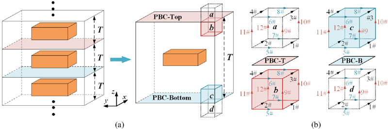
Figure 1: (a) Model of a simple periodic structure and its period T and (b) edges distribution of elements on periodic boundary.
In this paper, PBC is introduced to the SMF-FETD method with non-uniform grids for efficiently analyzing the electromagnetic characteristics of 3-D periodic structures with partial fine structures. Through the
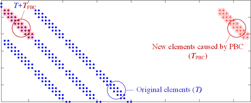
Figure 2: Partial non-zero elements distribution of .
Floquet theorem, the correspondence of the electric field components of the periodic boundary elements is given in detail. The mass and stiffness matrices of FETD with PBC no longer maintain the symmetric positive definite or symmetric semi-normal definite characteristic, which is a prerequisite for the SMF method. To this end, the new system matrix is split into two parts, PBC-independent and PBC-related, then through the generalized eigenvalue decomposition of the PBC-independent system and the unstable spatial modes are filtered out. Then the system matrix equation and time marching of the SMF-FETD and LES-SMF-FETD with PBC are obtained. PBC effectively reduces the computational domain of the periodic structure to one periodic unit cell then, combined with the non-uniform mesh scheme, the number of unknowns is further reduced while ensuring the mesh accuracy, effectively improving the computational efficiency of the SMF-FETD method for periodic structures. The accuracy of the SMF-FETD with PBC is validated by calculating the transmittance of an infinitely large dielectric plate. Furthermore, the efficiency of the proposed method is demonstrated through analysis of the transmission spectrum of the metallic grating with grooves.
II. NUMERICAL FORMULATIONS
A. Periodic boundary condition in 3-D
A simple periodic structure model with an infinite number of periodic unit cells T along the z-direction is shown in Fig. 1 (a), according to the Floquet theorem:
| (1) |
which means the physical structure and the field distributions of each unit cell T are the same. The computational domain is restricted to any single T by PBC according to (1), then the electromagnetic characteristics of the entire periodic structure can be equated by this unit cell. Because of the PBC, the boundary elements b and c are located inside the computational domain, and a and d are located outside. Elements a and c differ by one period T in the z-direction, as do b and d. At this time, the electric field distributions on the boundary elements satisfy the following:
| (2) | |||
where i denotes the edge number of the boundary elements.
The edges at the periodic boundary participate in the construction of the computational domain’s inner and outer boundary element matrices. As shown in Fig. 1 (b), take the PBC-Top surface as an example, the edges of the PBC surface not only participate in the b-element matrix construction as the 3#, 4#, 6#, and 8# edges but also participates in the a-element matrix construction as the 1#, 2#, 5#, and 7# edges. When forming the system matrices, according to (A.), the coupling relationship of the a-element edges can be directly replaced by the corresponding edges of the c-element. In other words, introduction of PBC is realized by the extra special coupling relationship between the b-elements and c-elements, which will change the number and distribution of the non-zero elements of the original system mass matrix and stiffness matrix ofFETD.
B. SMF-FETD with periodic boundary conditions
With the new system mass matrix and stiffness matrix , the matrix equation of FETD with PBC can be written as:
| (3) |
where denotes the correlation coefficient vector of the edge basis function and denotes the excitation vector. The core of the SMF-FETD method is the generalized eigenvalue analysis of the numerical system, which requires that the system matrices must be symmetric positive or semi-positive definite [12]. Due to the non-zero elements distribution given in Fig. 2, the new non-zero elements caused by the introduction of PBC may located at the same or different positions with the original non-zero elements of T, resulting in the asymmetric characteristic of . Similar to , is also asymmetric and its non-zero elements distribution is more complex. Split the asymmetric matrices and into two parts as shown in (4), symmetric matrices T and S are not relevant to PBC, while asymmetric matrices and are:
| (4) |
Performing a generalized eigenvalue analysis on (3), the matrix composed of the eigenvectors of unstable spatial modes under a given large time step is denoted as . Combined with (4), the matrix equation of SMF-FETD with PBC can be obtained:
| (5) |
The central-difference scheme with the explicit solution is used to discrete time variables of (5), the time marching of SMF-FETD with PBC is as follows:
| (6) |
Further through the LES [13], by replacing in (5) and (B.) with , which is composed of the eigenvectors of the unstable modes obtained from the local system containing the fine edges and their coupling coarse edges, the matrix equation and time marching of the LES-SMF-FETD with PBC can be obtained.
III. NUMERICAL RESULTS
A. Transmission coefficient of an infinitely large dielectric plate
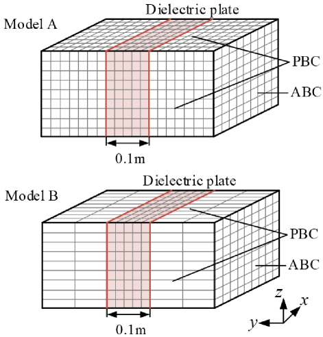
Figure 3: Mesh distribution of computational domain.
The planar Gaussian pulse with the relevant parameters and is incident vertically along the y- direction on an infinitely large dielectric plate of thickness 0.1 m and relative permittivity . The mesh distribution of different computational models and boundary settings are shown in Fig. 3, the absorbing boundary condition (ABC) is set in the y-direction while the PBC is set in other directions. The mesh scale of model A is 0.02 m0.02 m0.02 m resulting in 45144 unknowns, while the mesh scales of model B are 0.02 m0.02 m0.02 m and 0.02 m0.1 m0.02 m, resulting in 10044 unknowns. As shown in Fig. 4, the transmission coefficients obtained from different methods are in good agreement with the analytical solution, verifying the correctness of introducing PBC into the SMF-FETD with non-uniform mesh scheme.
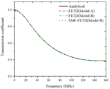
Figure 4: Transmission coefficient of infinite dielectric plate obtained from different methods.
B. Transmission characteristics of the metallic grating with grooves
As shown in Fig. 5, a metallic grating is composed of periodically arranged metal blocks with grooves. Its geometric parameters are: C 200 nm, C 200 nm, C 80 nm, a 80 nm, b 80 nm, and T 400 nm. The computational domain is discretized by 2300 non-uniform grids, where the scale of fine grid is 40 nm 8 nm 40 nm and the coarse grid is 40 nm 40 nm 40 nm. The maximum frequency of the planar Gaussian pulse is with relevant parameters and .
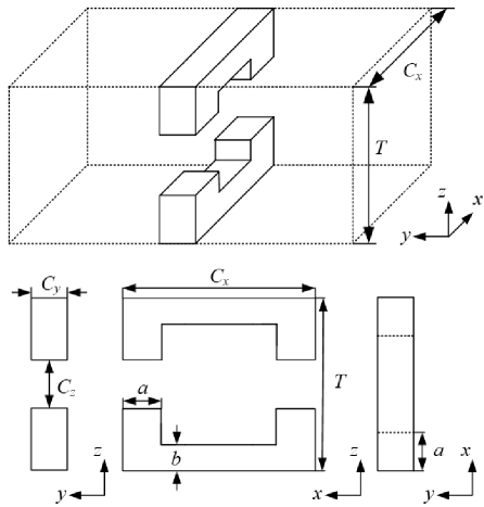
Figure 5: Schematic diagram of one period of the 3-D metallic grating with an indentation.
The transmission spectrums of the periodic metallic grating obtained from different methods are in good agreement, as shown in Fig. 6. The computational statistics of different methods are given in Table 1. SMF-FETD effectively expands the time step and improves the efficiency compared with FETD but requires high time and memory for global eigenvalue solution since the size of the system matrix is . LES-SMF-FETD effectively improves the deficiency of SMF-FETD through the LES method. The local system matrix of size contains the relationships between fine edges and their coupled coarse edges, which reduces the time and memory requirements for calculation. Thus, LES-SMF-FETD takes advantage of the SMF method to a greater extent.
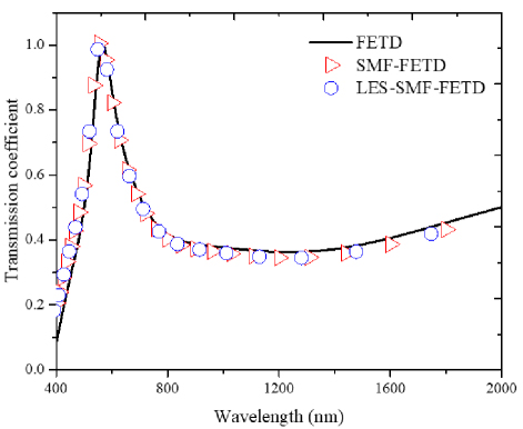
Figure 6: Transmission spectrums of the metallic grating obtained from different methods.
The effect of the variation of geometric parameters on the transmission spectrum of the metallic grating is analyzed. As shown in Fig. 7 (a), when C 200 nm, C 200 nm, and C 160 nm, as T increases, the frequency of the transmission peak becomes lower and the peak value decreases. When T 800 nm, C 200 nm, and C 160 nm, as shown in Fig. 7 (b), as C increases, the frequency of transmission peak becomes higher but the peak value decreases. At the same time, whenC 440 nm and C 520 nm, parts of electromagnetic waves with wavelength ranges of 400 nm to 700 nm are also transmitted.
Table 1: Simulation parameters of different methods
| Method | Time Step(fs) | Total Time/Eigenvalue Analysis Time (s) | Memory(MB) |
| FETD | 0.0100 | 425.42/— | 34.78 |
| SMF-FETD | 0.0468 | 332.72/167.83 | 3538.30 |
| LES-SMF-FETD | 0.0468 | 113.76/18.96 | 629.15 |
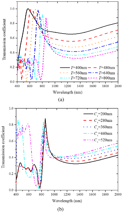
Figure 7: (a) Effect of T on the transmission spectrum and (b) effect of C on the transmission spectrum.
IV. CONCLUSION
In this paper, the periodic boundary is introduced into the 3-D SMF-FETD and LES-SMF-FETD method with non-uniform meshes by the Floquet theorem. The matrix asymmetry caused by PBC is solved by splitting the system matrix into two parts: PBC-independent and PBC-related. Unstable spatial modes are filtered out from the PBC-independent system through the SMF method. The SMF-FETD and LES-SMF-FETD with PBC are applied to the simulation analysis of the transmission properties of 3-D periodic structures. The correctness of the SMF-FETD method with PBC is verified by calculating the transmission coefficient of an infinite dielectric plate. The calculation of transmission spectrums of the metallic grating with grooves illustrates the efficiency and accuracy of the SMF-FETD and LES-SMF-FETD methods with PBC for simulating 3-D periodic structures.
ACKNOWLEDGMENT
This work was supported by the Shaanxi Natural Science Basic Research Project of Shaanxi Science and Technology Office (No. 2023-JC-QN-0673) and supported by the Key Core Technology Research Project of the 2024 Shaanxi Provincial Key Research and Development Plan (in the field of social development, NO. 2024SF2-GJHX-11).
REFERENCES
[1] Y. F. Mao, B. Chen, R. Xiong, Z. Cai, and Q. Chen, “A novel weakly conditionally stable FDTD method for periodic structures,” IEEE Antennas Wireless Propag. Lett., vol. 11, pp. 164-167, Feb. 2012.
[2] T. L. Liang, W. Shao, S. B. Shi, and H. Ou, “Analysis of extraordinary optical transmission with periodic metallic gratings using ADE-LOD-FDTD method,” IEEE Photonics Journal, vol. 8, no. 5, pp. 1-10, Oct. 2016.
[3] X. K. Wei, W. Shao, and H. Ou, “Domain decomposition CN-FDTD method for analyzing dispersive metallic gratings,” IEEE Photonics Journal, vol. 9, no. 4, pp. 1-18, Aug. 2017.
[4] V. Radisic and Y. Qian, “Broad-band power amplifier using dielectric photonic bandgap structure,” IEEE Microw. Guided Wave Lett., vol. 8, no. 1, pp. 13-14, Jan. 1998.
[5] M. N. Vouvakis, Z. Cendes, and J. F. Lee, “A FEM domain decomposition method for photonic and electromagnetic band gap structures,” IEEE Trans. Antennas Propag., vol. 54, no. 2, pp. 721-733, Feb. 2006.
[6] A. Pirhadi, H. Bahrami, and A. Mallahzadeh, “Electromagnetic band gap (EBG) superstrate resonator antenna design for monopulse radiation pattern,” Applied Computational Electromagnetics Society (ACES) Journal, vol. 27, no. 11, pp. 908-917, Nov. 2012.
[7] P. Bora, P. Pardhasaradhi, and B. Madhav, “Design and analysis of EBG antenna for Wi-Fi, LTE, and WLAN applications,” Applied Computational Electromagnetics Society (ACES) Journal, vol. 35, no. 9, pp. 1030-1036, Sep. 2020.
[8] L. Peng, C. L. Ruan, and J. Xiong, “Compact EBG for multi-band applications,” IEEE Trans. Antennas Propag., vol. 60, no. 9, pp. 4440-4444, Sep.2012.
[9] J. F. Lee, R. Lee, and A. Cangellaris, “Time-domain finite-element methods,” IEEE Trans. Antennas Propag., vol. 45, no. 3, pp. 430-442, Mar.1997.
[10] F. L. Teixeira, “Time-domain finite-difference and finite-element methods for Maxwell equations in complex media,” IEEE Trans. Antennas Propag., vol. 56, no. 8, pp. 2150-2166, Aug.2008.
[11] D. Jiao and J. M. Jin, “A general approach for the stability analysis of the time-domain finite-element method for electromagnetic simulations,” IEEE Trans. Antennas Propag., vol. 50, no. 11, pp. 1624-1632, Nov. 2002.
[12] W. Lee and D. Jiao, “An alternative explicit and unconditionally stable time-domain finite-element method for electromagnetic analysis,” IEEE J. Multiscale Multiphys. Comput. Tech., vol. 3, pp. 16-28, Mar. 2018.
[13] K. H. Fan, B. Wei, and X. B. He, “A subgridding unconditionally stable FETD method based on local eigenvalue solution,” IEEE Trans. Antennas Propag, vol. 69, no. 8, pp. 4695-4705, Aug.2021.
[14] Y. X. Wang, B. Wei, and K. H. Fan, “A spatial modes filtering FETD method with non-uniform subgridding mesh,” IEEE Microw. Wireless Tech. Lett., vol. 33, no. 6, pp. 635-638, June 2023.
[15] S. H. Zhao, B. Wei, and X. B. He, “Efficient implementation of unconditionally stable FDTD with the local eigenvalue solution,” Journal of Xidian University, vol. 49, no. 1, pp. 188-193, Feb. 2022.
[16] Y. X. Wang, B. Wei, and K. H. Fan, “Analysis of transmission characteristics of EBG structures by subgridding unconditionally stable FETD,” Applied Computational Electromagnetics Society (ACES) Journal, vol. 37, no. 9, pp. 921-932, Feb. 2023.
BIOGRAPHIES

Yixin Wang was born in Xi’an, Shaanxi, China, in 1995. She received the B.S. degree in electromagnetic wave propagation and antenna and the Ph.D. degree in physics from Xidian University, Xi’an, China, in 2017 and 2023, respectively. She is currently working as a physics teacher at Shaanxi Police College. Her current research interests include the finite-element time-domain method and its related methods.

Bing Weiwas born in Tianshui, Gansu, China, in 1970. He received the B.S. degree in physics from Beijing Normal University, Beijing, China, in 1993, and the Ph.D. degree in radio science from Xidian University, Xi’an, China, in 2004. From 1993 to 1998, he was a physics teacher at Tianshui Normal University, Tianshui, China. From 1998 to 1999, he was a physics teacher at Baoji University of Arts and Science, Baoji, China. Since 2004, he has been with Xidian University. Currently, he is a professor at Xidian University. His research interests include investigations of electromagnetic field theory, numerical field computation, and short pulse interactions om complex objects.
Kaihang Fan was born in Linfen, Shanxi, China, in 1990. She received the B.S. degree in electronic information science and technology and the Ph.D. degree in radio science from Xidian University, Xi’an, China, in 2014 and 2021, respectively. She is currently working as a postdoctoral researcher at the School of Information and Communications Engineering, Xi’an Jiaotong University, Xi’an, China. Her current research interests include the finite-element time-domain method and the multi-physics problem.
Xinbo He was born in Shaanxi, China, in 1991. He received the B.S. degree in electromagnetic wave propagation and antennae and the Ph.D. degree in radio science from Xidian University, Xi’an, China, in 2014 and 2021, respectively. He is currently a Post-Doctoral Fellow with the School of Physics, Xidian University. His current research interests include the fields of electromagnetic scattering and the finite-difference time-domain method.
Sihan Zhao was born in Xi’an, Shaanxi, China, in 1995. She received the B.S. degree in communication engineering from Xi’an University of Post & Telecommunications, Xi’an, China, in 2017, and the Ph.D. degree in radio science from Xidian University, Xi’an, China, in 2023. She is currently a researcher with Science and Technology on Electromechanical Dynamic Control Laboratory. Her current research interests include the finite-difference time-domain method and its related methods.
ACES JOURNAL, Vol. 40, No. 2, 96–102
doi: 10.13052/2025.ACES.J.400202
© 2025 River Publishers