Design of Wilkinson Power Dividers with SITL Compensated Microstrip Bandpass Filters
Ravee Phomloungsri, Somkuan Srisawat, Somchat Sonasang, and Mitchai Chongcheawchamnan
1Department of Computer and Communication Engineering, Faculty of Technology, Udon Thani Rajabhat University, Udon Thani 4100, Thailand
phravee@gmail.com, somkaun.srisawat@gmail.com
2Department of Electronics Technology, Faculty of Industrial Technology, Nakhon Panom University, Nakhom Panom, 48000, Thailand
somchat.s@npu.ac.th
3Department of Electrical Engineering, Prince of Songkla University, Hat Yai, Songkhla 90110, Thailand
mitchai@coe.psu.ac
Submitted On: July 6, 2023; Accepted On: February 4, 2024
ABSTRACT
This paper presents a simple technique for improving performances of a conventional Wilkinson power divider. The technique is achieved by replacing bulky quarter-wave transmission lines with stepped impedance transmission lines (SITL) compensated coupled lines. With the internal function of bandpass filter integrated with the proposed coupled lines, the spurious response at harmonics frequencies that normally exists in the conventional divider is considerably reduced. Simulated and measured results at 2.1 GHz operating frequency of the proposed and conventional Wilkinson power divider were compared. The proposed divider achieves -3.8 dB insertion loss and more than 25 dB return loss across 10 fractional bandwidth. Based on this measurement, the proposed circuit achieves more than 34.5 dB suppression at the harmonic frequency.
Index Terms: Harmonic suppression, parallel-coupled line, step impedance transmission line, Wilkinson power divider.
I. INTRODUCTION
Microwave circuits have many applications such as filter circuit [1], reflectometer [2], diplexer [3], Wilkinson power divider/combiner [4, 5, 6], microstrip add-drop multiplexer [7, 8], and microwave sensor application [9, 10]. Since the microwave circuit is implemented and developed with the microstrip substrate material, the Wilkinson power divider is a general microwave and millimeter wave communication circuit [11].
The Wilkinson power divider was first introduced by Wilkinson [4] and is an essential component for microwave and millimeter-wave applications. It is widely used because of its helpful property of being perfectly matched at all ports and sound isolation between the output ports [11, 12]. Moreover, the Wilkinson power divider is widely used to design and implement microstrip coupled lines. The non-homogeneous nature of physical parallel coupled lines microstrip gives rise to spurious frequencies, particularly beyond the second harmonic frequency. To address this issue, compensation techniques such as inductive [13, 14] and capacitive [15, 16] methods are commonly employed. These techniques play a crucial role in mitigating the effects of non-idealities, thereby enhancing the performance and reliability of microstrip-based circuits. Notwithstanding, researchers have presented Wilkinson power divider techniques for harmonic suppression frequencies such as an anti-coupled line [17], parallel-coupled line structure [18], looped coupled-line [19], inductively loaded microstrip line [20], and bandpass or band stop filter [21, 22, 23]. The utilization of power divider applications needing a narrowband divider and bandpass filter designs are prevalent in the construction of I-Q demodulator topologies, leading to the creation of simplified circuits [24, 25, 26, 27]. For RF and microwave circuit design, including balanced amplifiers, phase shifters, image rejection mixers, I/Q modulators, and circularly polarized antenna polarizers, the techniques mentioned above can produce spurious harmonic frequencies. However, those techniques have limitations on the complexity of the circuit.
The Wilkinson power divider consists of two quarter-wavelength branches of transmission lines with a characteristic impedance and a termination resistor, as
shown in Fig. 1. The power divider is designed based on the electrical length of a desired fundamental frequency. Still, high-order harmonic signals usually appear at the output ports due to the periodic characteristics of the transmission lines. Using the quarter-wavelength branches of transmission lines will unavoidably lead to poor selectivity in each transmission path. Intuitively, the selectivity can be improved by adding an extra high-order bandpass filter before the input or after each output port of the power divider. Still, the sizeable total circuit area may be a terrible problem. The concept of this research work is to add the BPF function in the divider without circuit size trade-off as shown in Figs. 1 and 2, a quarter-wave transformer is replaced with a transformer with integrated BPF. The basic theory of the proposed topology is described in Section II. Design and experimental results will be described in Section III. The paper is finally concluded in Section IV.
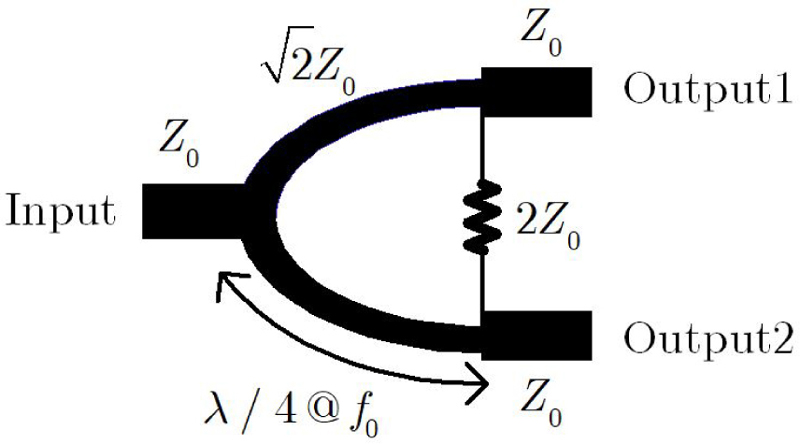
Figure 1: Schematics of conventional Wilkinson power divider.
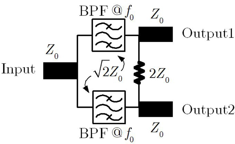
Figure 2: Schematics of the proposed integrated bandpass filter Wilkinson power divider.
II. THEORY
A. The step impedance transmission lines resonator
Step impedance transmission lines (SITL) are non-uniform transmission lines, which were used in the filter design to reduce the circuit sizes [28, 29], to shift the spurious to higher band, and to suppress multiple spurious passband [29]. The SITL employed in this paper is shown in Fig. 1. It consists of two cascaded transmission lines with characteristic impedances and and electrical lengths and , respectively. In this technique,, so the impedance ratio is aligned between . As shown in Fig. 4, the SITL is proposed to connect at the coupled lines port to suppress signal transmission between port 1 and port 3 of the coupled lines. To achieve this condition, the electrical parameters of coupled lines should be chosen optimally.
Based on the above-mentioned condition, the optimum directivity at operating frequency of coupled-line occurs when the signal transmission of ports 1 and 3 is enforced to be nearly zero or , which will occur as the driving point impedance from the coupled port to the SITL for this design is also enforced to [30] :
| (1) |
where = and .
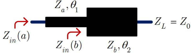
Figure 3: Schematic of the proposed step impedance transmission line.
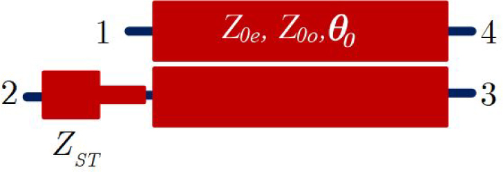
Figure 4: The proposed coupled lines based SITL compensated coupled lines.
The input impedance of the SITL section at operating frequency is related to the coupled lines electrical parameters. To preserve or minimize the change of the coupling coefficient of the proposed coupled lines, its electrical length should be shortened and computed from:
| (2) |
B. Proposed BPF resonator based SITL compensated coupled lines
Based on the impedance parameters [11], the relationship between voltages and currents at each port shown in Fig. 5, are given as follows:
| (3) |
| (4) |
| (5) |
| (6) |
where and (n = 1..4 ) are each ports voltage and current. From the initial condition in Fig. 5, where and , then 4-port network is transformed to 2-port bandpass filter, and the relationship between voltage, current and impedance of 2-port network are as in equation (7):
| (7) |
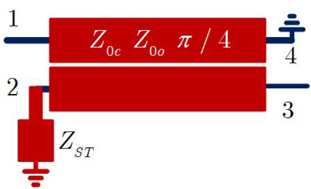
Figure 5: The proposed BPF resonator based SITL compensated coupled lines.
where
| (8) |
| (9) |
| (10) |
| (11) |
when
| (12) |
and
| (13) |
From equation (7), the input reflection coefficient and the forward transmission coefficient of the synthesized BPF resonator are as shown in equations (14) and (15) :
| (14) |
| (15) |
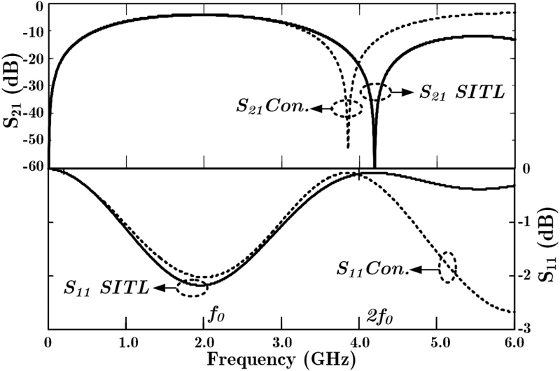
Figure 6: S-parameters of 2.1 GHz conventional and the proposed BPF resonators.
Table 1: Parameters of the -10 dB coupled lines for BPF resonator at 2.1 GHz
| Sections | Impedances | Coupler’s Length , rad | W,S,L |
|---|---|---|---|
| Cpl-SITL | |||
| 21.00 | |||
| Con-Cpl | |||
| 25.00 | |||
| SITL | , | ||
These concepts, theories, and equations were employed to design a BPF resonator based SITL coupled lines at an operating frequency of 2.1 GHz. In this paper,-10 dB coupled lines with even and odd-mode impedances of , , for a 50 system is chosen to design the proposed BPF resonator. and are calculated from equations (1) and (2). After that the impedance and electrical degree were used to calculate the electrical parameters , and , of SITL, respectively. Table 1 lists the electrical parameters of the conventional and the proposed BPF resonator based SITL compensation design for -10 dB while the electrical length of the conventional Wilkinson circuit is rad and the proposed Wilkinson circuit is rad, with the circuit size reduced by rad in electrical length. The parameters of the SITL have an electrical length of 8 rad, respectively.
The frequency response vs. return loss curve of the conventional and the proposed BPF resonator based SITL compensated coupled lines simulated in this study are shown in Fig. 6. The simulation results of and presented frequency response at the same level compensated by STIL. The resulting frequency at is higher than in the conventional.
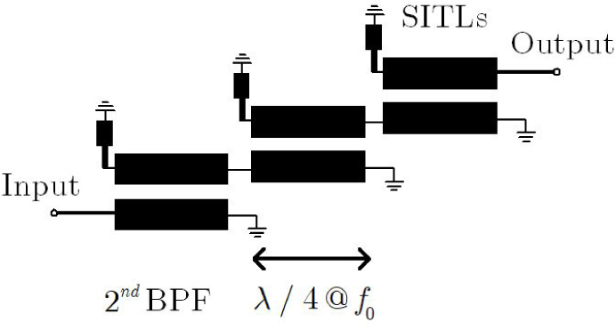
Figure 7: Schematic of the proposed order BPF SITL compensated coupled lines [31].
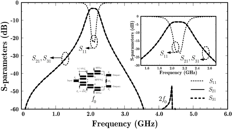
Figure 8: Simulation results in S-parameters of the proposed Wilkinson power divider.
C. Transmission lines modified for second-order BPF frequency response characterization
In the paper presented here, the filter, as shown in Fig. 7 is designed using the Chebyshev bandpass prototype technique [32, 33]. The element values for the considered prototype were proposed to determine the even- and odd-mode impedances by using the admittance inverter. The method of using a higher-order parallel coupled-line bandpass filter to replace transformer [32, 33] can be utilized in the proposed equal-split Wilkinson power divider with favorable selectivity. The SITLs compensation coupled lines BPF design equations of the proposed divider can be employed [33], where is the filter’s order, and are the even- and odd-mode characteristic impedances of each coupled-line section, and are the system impedance and the 3-dB fractional bandwidth of the filter,,i=1,2,3,…,N+1, are the admittance inverters (J-inverters),,i=1,2,3,…,N+1 are the lumped element values for low-pass filter prototype. In this conventional Wilkinson power divider, the characteristic impedance of each branch of quarter-wavelength transmission lines in Fig. 1 is . In the proposed technique, each quarter-wavelength branch of transmission lines in the Wilkinson power divider can be replaced by the even-order coupled lines bandpass filter where the system characteristic impedance of the filter is as shown in Fig. 8 and the proposed power divider has employed order BPF based SITL compensated coupled lines instead of an ordinary quarter-wavelength branch of transmission lines to improve the desired selectivity in each output signal.
III. DESIGN AND EXPERIMENTAL RESULTS
To enhance the selectivity performance of the proposed Wilkinson power divider, the circuit prototype has been designed and fabricated on AD260 microwave substrate with the following design parameters: =2.60, =1.00 mm, =35m and =0.0017. The centre frequency and 3-dB fractional bandwidth of each filter transformer (both upper- and lower-BPF) are around 2.1 GHz and 5 fractional bandwidth. The corresponding design parameters of each 0.5 dB equal-ripple Chebysheve filter transformer are =1.4029, =0.7071, =1.9841, =0.2366, =0.0792, and =0.2366. The even- and odd-mode characteristic impedances of each coupled-line section are =91.40 ,=57.93 ,=76.75 , =65.55 , =60.89 , and =87.93 , respectively. The physical and electrical design parameters of SITLs compensated BPF are shown in Table 2.
Table 2: Parameters of the Wilkinson power divider with integrated BPF at 2.1 GHz
| Sections | Impedances | Coupler’s Length , rad | W,S,L |
|---|---|---|---|
| Coupled lines 1 | |||
| 21.00 | |||
| Coupled | |||
| lines 2 | 19.60 | ||
| Coupled | , | ||
| lines 3 | 21.00 | ||
| SITLs | |||
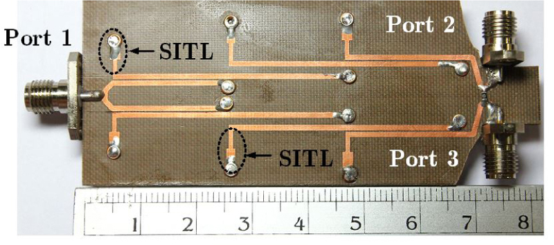
Figure 9: PCB photograph of the proposed Wilkinson power divider.
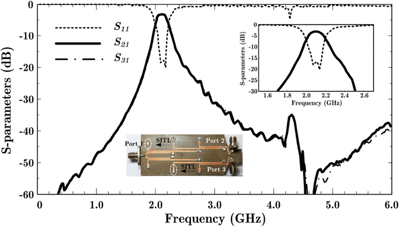
Figure 10: Measured results s-parameters of the proposed Wilkinson power divider.
Table 3: The comparison of Wilkinson power dividers
| Ref. | Techniques | Harmonic Suppression |
|---|---|---|
| Ref [4] | Open stub | |
| Ref [6] | LPFs | |
| Ref [12] | Lumped-distributed | NA |
| Ref [17] | Anti-coupled line | |
| Ref [18] | Parallel coupled line | |
| Ref [19] | Looped coupled-line | NA |
| Ref [21] | Open-short stubs | |
| Ref [23] | BSF | |
| This work | BPF |
In Fig. 9, the simulated result of the proposed Wilkinson power divider shows the suppression performances at 4.2 GHz below the desired frequency of 2.1 GHz more than 43 dB. The measurement was performed with the E5071C Vector Network Analyzer as shown in Fig. 10, which is in good agreement with the simulated result. The implemented circuit has the measured results -4.13 dB, -4.12 dB, -19.5 dB at the desired frequency 2.1 GHz and presents the suppression performances at 4.2 GHz more than 34.5 dB. The photograph of the PCB of the proposed frequency doubler based on a square ring resonator is shown in Fig. 11. The circuit size excluding the input and output SMA connectors of the proposed Wilkinson power divider is around 22.27 cm. Table 3 presents a summary of previous studies alongside our proposed circuit. Our design employs BPF coupled lines, which offers a simpler approach compared to the more intricate designs employed by other researchers. As a result, the proposed Wilkinson power divider proves to be more suitable for practical implementation.
IV. CONCLUSION
A modified Wilkinson power divider with integrated SITL compensated coupled lines bandpass filters has been proposed. The proposed topology has many attractive characteristics such as low insertion loss, good selectivity in each output signal path, wide stop band, and ease of design and implementation. The level of spurious response at a harmonic of the proposed Wilkinson power divider is then 34.5 dB at the harmonic frequency. It is believed that the proposed power divider can be simply modified for many microwave systems.
ACKNOWLEDGMENT
The authors would like to demonstrate gratitude toward the Faculty of Industrial Technology of the Nakhon Phanom University for research time and the Department of Computer and Communication Engineering (CCE), Faculty of Technology, Udon Thani Rajabhat University (UDRU) for the research grant, instrumentation and materials support.
REFERENCES
[1] I. J. Bahl, Lumped Elements for RF and Microwave Circuits, Artech house, 2022.
[2] S. Tantiwit, S. Somwong, and M. Chongcheawchamnan, “Dual-Frequency Six-Port Reflectometer Technique for Quality Determination of Para Rubber Latex,” in 2022 International Electrical Engineering Congress (iEECON), pp. 1-5, IEEE,2022.
[3] S. Srisathit, S. Patisang, R. Phromloungsri, S. Bunnjaweht, S. Kosulvit, and M. Chongcheawchamnan, “High isolation and compact size microstrip hairpin diplexer,” IEEE Microwave and Wireless Components Letters, vol. 15, no. 2, pp. 101-103, 2005.
[4] E. J. Wilkinson, “An N-way hybrid power divider,” IRE Transactions on Microwave Theory and Techniques, vol. 8, no. 1, pp. 116-118, 1960.
[5] M. Hayati and S. Roshani, “A novel Wilkinson power divider using open stubs for the suppression of harmonics,” Applied Computational Electromagnetics Society (ACES) Journal, pp. 501-506, 2013.
[6] S. Roshani, S. Koziel, S. Roshani, M. B. Jamshidi, F. Parandin, and S. Szczepanski, “Design of a patch power divider with simple structure and ultra-broadband harmonics suppression,” IEEE Access, vol. 9, pp. 165734-165744, 2021.
[7] S. Sonasang, M. Jamsai, M. Jalil, N. T. Pham, K. Ray, N. Angkawisittpan, P. Yupapin, S. Boonkirdram, M. A. Palomino-Ovando, M. Toledo-Solano, K. Misaghian, and J. Lugo, “Multiband Rabi antenna using nest microstrip add-drop filter (NMADF) for relativistic sensing applications,” Heliyon, vol. 9, no. 2, 2023.
[8] S. Sonasang, P. Prabpal, P. Sirikan, P. Hakaew, N. T. Pham, P. Yupapin, K. Ray, and S. Boonkirdram, “Rabi antenna using microstrip add-drop multiplexer for electron warp speed investigation,” Chinese Optics Letters, vol. 20, no. 7, p. 073901, 2022.
[9] S. Sonasang and R. Phromloungsri, “The measurement of water level based on parallel-coupled lines with capacitance compensation,” Creative Science, vol. 14, no. 2, pp. 245039-245039, 2022.
[10] S. Sonasang, S. Srisawat, R. Phromloungsri, W. Rattanangam, and N. Angkawisittpan, “Liquid Level Measurement Using Sensors with Microstrip Parallel Coupled Lines,” in 2019 IEEE 2nd International Conference on Power and Energy Applications (ICPEA), pp. 106-109, IEEE, 2019.
[11] D. M. Pozar, Microwave Engineering, John Wiley & Sons, 2011.
[12] M. Chongcheawchamnan, N. Siripon, and I. Robertson, ‘‘Design and performance of improved lumped-distributed Wilkinson divider topology,” Electronics Letters, vol. 37, no. 8, pp. 501-503, 2001.
[13] R. Phromloungsri, M. Chongcheawchamnan, and I. D. Robertson, “Inductively compensated parallel coupled microstrip lines and their applications,” IEEE Transactions on Microwave Theory and Techniques, vol. 54, no. 9, pp. 3571-3582, 2006.
[14] S. Sonasang and N. Angkawisittpan, “Design of microstrip parallel-coupled lines with high directivity using symmetric-centered inductors,” Applied Computational Electromagnetics Society (ACES) Journal, pp. 657-663, 2021.
[15] M. Dydyk, “Accurate design of microstrip directional couplers with capacitive compensation,” in IEEE International Digest on Microwave Symposium, pp. 581-584, IEEE, 1990.
[16] M. Dydyk, “Microstrip directional couplers with ideal performance via single-element compensation,” IEEE Transactions on Microwave Theory and Techniques, vol. 47, no. 6, pp. 956-964, 1999.
[17] J. Zhang, L. Li, J. Gu, and X. Sun, “Compact and harmonic suppression Wilkinson power divider with short circuit anti-coupled line,” IEEE Microwave and Wireless Components Letters, vol. 17, no. 9, pp. 661-663, 2007.
[18] X. Yu, S. Sun, and Y. Liu, “Design of wideband filtering power dividers with harmonic suppression based on the parallel-coupled line structures,” Applied Computational Electromagnetics Society Journal (ACES), pp. 468-475, 2018.
[19] H. Zhu, A. M. Abbosh, and L. Guo, “Wideband four-way filtering power divider with sharp selectivity and wide stopband using looped coupled-line structures,” IEEE Microwave and Wireless Components Letters, vol. 26, no. 6, pp. 413-415, 2016.
[20] E. N. Mohamed, A. G. Sobih, and A. M. El-Tager, “Compact Wilkinson power divider with Inductive loaded microstrip line for harmonics suppression,” in 2016 IEEE Middle East Conference on Antennas and Propagation (MECAP), pp. 1-4, IEEE, 2016.
[21] S. Lotfi, S. Roshani, S. Roshani, and M. S. Gilan, “Wilkinson power divider with band-pass filtering response and harmonics suppression using open and short stubs,” Frequenz, vol. 74, no. 5-6, pp. 169-176, 2020.
[22] H. S. Vaziri, S. Zarghami, F. Shama, and A. H. Kazemi, “Compact bandpass Wilkinson power divider with harmonics suppression,” AEU-International Journal of Electronics and Communications, vol. 117, p. 153107, 2020.
[23] R. Phromloungsri and S. Sonasang, “Design and implementation of a wilkinson power divider with integrated band stop filters based on parallel-coupled lines,” Applied Computational Electromagnetics Society (ACES) Journal, vol. 38, no. 3, p. 208, 2023.
[24] X. Wang, M. Yoshikawa, J. Kohagura, Y. Shima, R. Ikezoe, M. Sakamoto, T. Imai, Y. Nakashima, Z. Ma, I. Sakagami, and A. Mase, “A narrow band-pass filter type Wilkinson power divider for IQ demodulator in microwave interferometer system,” Journal of Instrumentation, vol. 10, no. 11, p. C11005, 2015.
[25] J.-H. Park, S.-J. Park, and M.-Q. Lee, ‘‘Quadrature Wilkinson power divider using cross-type short-circuited shunt stub for good amplitude and phase balance,” AEU-International Journal of Electronics and Communications, p. 154783, 2023.
[26] S. Zarghami and M. Hayati, “Narrow-band power dividers with wide range tunable power-dividing ratio,” Scientific Reports, vol. 12, no. 1, p. 17351, 2022.
[27] P. Cheong, K.-I. Lai, and K.-W. Tam, “Compact Wilkinson power divider with simultaneous bandpass response and harmonic suppression,” in 2010 IEEE MTT-S International Microwave Symposium, pp. 1588-1591, IEEE, 2010.
[28] M. Makimoto and S. Yamashita, “Bandpass filters using parallel coupled stripline stepped impedance resonators,” IEEE Transactions on Microwave Theory and Techniques, vol. 28, no. 12, pp. 1413-1417, 1980.
[29] S.-C. Lin, P.-H. Deng, Y.-S. Lin, C.-H. Wang, and C. H. Chen, “Wide-stopband microstrip bandpass filters using dissimilar quarter-wavelength stepped-impedance resonators,” IEEE Transactions on Microwave Theory and Techniques, vol. 54, no. 3, pp. 1011-1018, 2006.
[30] S. Kumpang, R. Phromloungsri, and M. Chongcheawchamnan, “Design high-directivity parallel-coupled lines with step-impedance transmission lines,” in 2007 Asia-Pacific Microwave Conference, pp. 1-4, IEEE, 2007.
[31] S. Kumpang, R. Phromloungsri, M. Chongcheawchamnan, M. Krairiksh, and I. Robertson, “Design and application of microstrip parallel-coupled lines employing step-impedance transmission-line compensation,” IET Microwaves, Antennas & Propagation, vol. 3, no. 3, pp. 410-415, 2009.
[32] G. Mahttei, L. Young, and E. Jones, “Microwave filters, impedance matching networks, and coupling Structure,” Norwood, MA, Artech House, 1980.
[33] J.-S. G. Hong and M. J. Lancaster, Microstrip Filters for RF/Microwave Applications, John Wiley & Sons, 2004.
BIOGRAPHIES

Ravee Phromloung was born in Khon Kaen, Thailand. He received the B.Sc. (Applied Physics in Solid State Electronics) from King Mongkut Institute of Technology, Ladkrabang (KMITL), in 1992, M.Eng. in Electrical Engineering (Telecommunication) from Mahanakorn University of Technology (MUT), in 2000 and he is currently working toward the D.Eng. in Electrical Engineering in MUT. From 1992 to 2009, he joined MUT as a lecturer in the telecommunication engineering department. Currently, he is an assistant professor in the Department of Computer and Communication Engineering at Udon Thani Rajabhat University. His research interests include IoT/Automation system, and RF/Microwave circuits design.

Somkuan Srisawat was born in Nongbua Lamphu, Thailand. He received the B.Eng. (Electronics Engineering) from Udon Thani Rajabhat University, in 2011, M.Eng. in Electrical and Computer Engineering from Mahasarakham University (MSU), in 2019, Thailand. Currently, he is working in the Department of Computer and Communication Engineering at Udon Thani Rajabhat University. His research interests include IoT/Automation system, and RF/Microwave circuits design.

Somchat Sonasang was born in Nongbua Lamphu, Thailand. He received the B.Eng. (Electronics and Telecommunication-Telecommunication) from Rajamangala University of Technology Isan(RMUTI), Nakhon Ratchasima Campus, in 2006, M.Eng. in Electrical Engineering from Khon Kaen University (KKU), in 2009, Ph.D. degree in electrical and computer engineering from Mahasarakham University (MSU), Maha Sarakham, Thailand, in 2021. He is currently working in the Department of Electronic Technology, Faculty of Industrial Technology, Nakhon Phanom University, Thailand. His current research interests are microwave circuits, electromagnetic material characterization, non-destructive tests, Rabi oscillation and antenna.

Mitchai Chong (Senior Member, IEEE) was born in Bangkok, Thailand. He received the B.Eng. degree in telecommunication from the King Mongkut’s Institute of Technology Ladkrabang, Bangkok, in 1992, the M.Sc. degree in communication and signal processing from Imperial College London, London, U.K., in 1995, and the Ph.D. degree in electrical engineering from the University of Surrey, Guildford, U.K., in 2001. He joined the Mahanakorn University of Technology, Bangkok, as a Lecturer, in 1992. In 2008, he joined the Faculty of Engineering, Prince of Songkla University, Songkhla, Thailand, as Professor. His current research interests include deep learning, microwave circuit design and microwave techniques for agricultural applications.
ACES JOURNAL, Vol. 38, No. 12, 958–964
doi: 10.13052/2023.ACES.J.381205
© 2023 River Publishers