Mitigation of Feed Horn Overlapping Condition for Multi-beam Parabolic Reflector Antenna
Nur Faiqah Fauzi, Nurul Huda Abd Rahman, Yoshihide Yamada, Robi’atun Adayiah Awang, and Idnin Pasya
1Antenna Research CentreCollege of Engineering, Universiti Teknologi MARA 40450 Shah Alam, Selangor, Malaysia
nurulhuda0340@uitm.edu.my, nfaiqahfauzi@gmail.com, robiatun@uitm.edu.my
2Malaysia-Japan International Institute of Technology (MJIIT) Universiti Teknolgi Malaysia, Jalan Yahya Petra 54100 Kuala Lumpur, Malaysia
yoshihide@utm.my
3Department of Computer Science and Engineering, Division of Computer Engineering, University of AizuAizuwakamatsu 965-8580, Japan
idnin@u-aizu.ac.jp
Submitted On: July 6, 2023; Accepted On: January 14, 2024
ABSTRACT
In designing a contoured beam for communication satellite services, a reflector antenna remains the most preferred option. Previously, a multi-beam technique employing many feed horns at optimal feed positions was proposed to obtain a precise contour beam for Malaysia. However, it has led to feed horn overlapping when the beams were arranged closely. Therefore, this issue of beam allocation and feed horn size shall be addressed. In this article, an analysis of the relationship between feed position and beam direction is analysed through the Beam Deviation Factor (BDF). As a result, a useful design chart was derived for no feed horn overlapping conditions, which determines beam separation and feed horn size at different values of F/D. A practical application showing the Peninsular Malaysia beam coverage was demonstrated to validate the derived correlation. As a result, five multi-beams have been successfully designed with no overlapping feed horns. Through simulation, an excellent contour beam for Peninsular Malaysia was justified, featuring low side lobes, narrow beam width and high gain.
Index Terms: Beam shaping, Feed horn overlapping, Multi-beam, Parabolic reflector antenna, Satellite antenna.
I. INTRODUCTION
In Malaysia, the MEASAT Satellite System is currently the provider of satellite communication services through the MEASAT-3 satellite. These services include C-band and Ku-band services for the direct-to-home (DTH), video distribution and other Fixed Satellite Service (FSS). The Ku-band beams offer high-quality DTH coverage across South Asia, Indonesia and Malaysia. Geographically, the Malaysia region consists of two main parts, Peninsular Malaysia and the Borneo region. Figure 1 demonstrates the Malaysia region from MEASAT-3’s satellite point-of-view located at the orbital slot of 91.5 East longitude [1]. By observing the satellite’s footprint for Malaysia, the beam shape can be further improved by concentrating on high-density areas and thus, will result in a more accurate contoured beam for Malaysia.
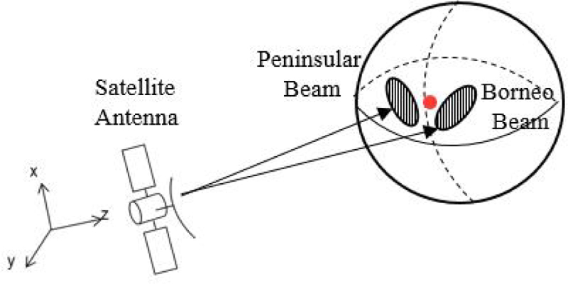
Figure 1: Illustration of Malaysia from satellite point-of-view.
Contoured beam antennas have been widely used for various applications such as broadcasting, military operations and high-speed internet access. These applications require a highly concentrated and consistent signal to ensure uninterrupted data transmission to the coverage areas. While a single narrow beam can be used for the operation, it has limited coverage on the earth surface. Therefore, two techniques can be employed to produce contoured beams, such as reflector shaping or a combination of multiple beams. Reflector shaping may be accomplished by creating the proper reflector curvature [2–4]. Among the available techniques, the multi-beam antenna (MBA) has been used to combine multiple narrow beams into the desired beam shape using a reflector antenna and multiple feed system [5–8]. In MBA, an array of feeds can be arranged simultaneously based on a precise positioning technique to generate a contoured beam of the desired area. By adopting this multi-beam concept, a precise contoured beam of Malaysia coverage can be accurately designed.
In the previous works on achieving Malaysia coverage by multi beams, feed horn overlapping problem has occurred. One technique used to address this issue was to replace the horn with a patch antenna [9–12]. However, in that work, the proposed mitigation technique was through the implementation of planar arrays, but a detailed analysis of how to solve the original overlapping horn issues was not provided. Another investigation of radiation properties has already been conducted [13], however, the theoretical and simulation results only focused on gain and side-lobe levels without providing information on how to overcome the feed overlapping.
When designing multi beams with multiple feeds, feed positioning becomes very important. In [14] the best feed position was obtained using ray tracing method. The feed positions were determined based on the concentrated point of all rays, based on caustic dependency on focal-length-to-diameter-ratio (F/D). However, to clarify the adequateness of the feed position in relation of F/D and beam direction, the method of focal region ray tracing is considered to be more reliable.
In this article, the feed overlapping issues are demonstrated and solved through the optimization of antenna parameters via theoretical analysis and the derivation of a design graph. The analysis is conducted in three steps. First, the correlation between feed displacement and beam separation is derived using technical parameters of the antenna such as reflector diameter, D, horn size, H, and wavelength, . Through the derived expression, the beam separation is presented in terms of the antenna beam width, meanwhile, the feed displacement is denoted in terms of feed horn size. As a result, a design graph showing the size of the feed horn that can be implemented to mitigate overlapping horn issues is determined. Next, to ensure the adequateness of the design graph, a practical example of the Malaysia coverage employing five multi-beam antennas is demonstrated.
II. ANALYSIS OF HORN OVERLAPPING
A. Fundamental equation of parabola
Figure 2 shows the configuration of the parabolic reflector antenna system used in this analysis. The reflector edge angle, , is determined as shown in the figure, while the half power beam width of a horn radiation pattern is indicated as and the half power beam width of a reflector radiation pattern is indicated as . The radiated beam direction, , is determined by the feed horn shift angle, . The detailed parameters used in this study are shown in Table 1.
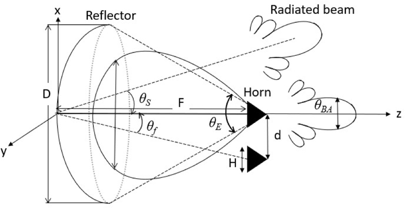
Figure 2: Antenna parameters.
Table 1: Parabolic reflector parameters
| Parameters | Symbols | |
|---|---|---|
| Frequency | f | |
| Wavelength | ||
| Parabola | Reflector diameter | D |
| Focal length | F | |
| Reflector edge angle | ||
| Half-power beam width of a reflector | ||
| Beam separation angle | ||
| Feed | Feed horn size | H |
| Half-power beam width of a horn | ||
| Feed horn displacement | d | |
| Feed horn displacement angle |
The relationship between the fundamental structural parameters of a parabolic reflector, namely the reflector edge angle, , focal length, F, and diameter, D, is expressed by equation (1):
| (1) |
By applying the approximation of tan (/4) /4 (rad), equation (1) is simplified as equation (2):
| (2) |
The beam width of the radiated beam, , is given by equation (3):
| (3) |
Here, the coefficient of 1.14 is determined based on the tapered aperture distribution of -10dB edge level [14].
B. Feed horn equations
The feed horn’s size and its relation to the reflector edge level is important. Equation (4) describes the half power beam width of the conical feed horn, , which is inversely proportional to its aperture size, H:
| (4) |
The accuracy of the coefficient 1.2 used in equation (4) will be discussed in detail in section III part B.
Figure 3 illustrates the relationship between and . Generally, the beam width, , is almost same as the angle to the first null point, , as shown in the figure. In order to show the relation of and , an value is introduced, as shown by equation (5):
| (5) |
When =1, =2 indicates that the null point corresponds to the reflector edge. At =0.5, = meaning that the reflector edge is illuminated by the feed horn at a level of -3dB (edge level). In the practical reflector design, the reflector edge level of around -10dB is selected. Then, an value of around 0.7 is suitable.
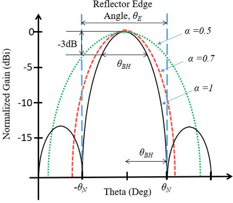
Figure 3: Comparison of the reflector edge level with different values of .
By applying equations (2) and (4) to equation (5), the approximate relation between the size of the horn, H/ and F/D is derived as shown in equation (6):
| (6) |
The importance of equation (6) is that the horn size, H, is related to F/D with a parameter .
C. Beam direction and feed position
Figure 2 illustrates how the feed position, beam direction and feed displacement are related. The feed shift angle, , can be approximated in terms of the feed displacement, d, by the equation:
| (7) |
As for the relation of the feed displacement, d, to the radiation beam shift, , a beam deviation factor (BDF) equation can be used [15]:
| (8) |
The numerical data of BDF is shown in Fig. 4, which shows that the BDF value increases with an increase in F/D. However, the change in BDF value is relatively small between 0.8 to 1.0.
Figure 4: BDF value versus F/D.
By applying equation (7) to equation (8), is expressed by feed displacement, d, as in equation (9):
| (9) |
D. Beam separation
In designing beam allocations, the beam separation angle, , is determined by the beam width of the parabolic reflector, , by using the equation:
| (10) |
Here, is a parameter that determines the beam separation.
Figure 5 provides an example that illustrates the influence of values. When =1, the beam separation is similar to the beam width, , resulting in beam overlapping as shown in Fig. 5 (a). For 1, the beam separation becomes larger than the beam width, resulting in no beam overlapping, as shown in Fig. 5 (b).
Figure 5: (a) The relation between and when =1 and (b) The relation between and when 1.
E. No feed overlapping condition
Firstly, by applying equation (3) to equation (10), is expressed by the equation of 1.14/D. Then, by using the equation of equation (9), the following equation is obtained:
| (11) |
Using equations (6) and (11), F/D can be expressed as equation (12):
| (12) |
The following equation is derived to explain the relation between , d, and H.
| (13) |
The value of d/H is a key factor in judging feed overlapping. A value of d/H1 indicates that there is no overlapping, while a value of and when d/H1 indicates overlapping. The critical condition is when d/H=1.
Figure 6: Relation of F/D and at d/H=1.
To determine the relation between and , it is useful to consider the condition of d/H=1. The result is shown in Fig. 6 for various antenna F/D. On the line =0.62, the corresponding value yields d/H=1. If is slightly larger, it results in d/H1 and, thus, no overlapping occurs. If is slightly smaller, d/H is less than 1 (d/H1) and overlapping occurs. In the practical antenna design presented in section III, F/D=1 is used. For this value, =0.62 and =1.3 are selected.
III. APPLICATION TO PRACTICAL REFLECTOR ANTENNA DESIGN
To ensure the accuracy of the feed position designing method discussed in section II, a practical antenna structure was designed for achieving a fine contour beam for Peninsular Malaysia coverage. To accomplish this, a multi-beam technique was employed, as shown in Fig. 7. In this figure, the boresight of the satellite antenna is aligned nearby to Riau Island (0,0) based on the geostationary satellite location at (3,1). Five beams denoted as B1, B2, B3, B4 and B5 are arranged to form a precise beam coverage for the Peninsular Malaysia region.
Figure 7: Beam coverage of Peninsular Malaysia area.
A. Reflector antenna parameters
Table 2 shows the antenna parameters used to design the contoured beam for Peninsular Malaysia, which is divided into five small beams. The chosen operating frequency 7.5 GHz falls within the FSS planned band allocated for Malaysia. The antenna diameter, D, is set to 8.5 m to achieve narrow beam width, , of 0.3 based on equation (2). The focal length is set to 8.5 m, which results in an F/D ratio of 1. Using equation (1), the calculated value for reflector edge angle, , is 56. With =1.3, the beam separation angle, , is determined to be 0.39 through calculation using equation (9). The feed displacement, d, is calculated to be 0.064 m from equation (8).
Table 2: Detailed parameters of antenna design
| Item | Value |
|---|---|
| Frequency, f | 7.5 GHz |
| Reflector diameter, D | 8.5 m |
| Focal length, F | 8.5 m |
| Reflector edge angle, | 56 |
| Beam width of a reflector, | 0.3 |
| 1.3 | |
| Beam separation angle, | 0.39 |
| Feed horn displacement, d | 0.064 m |
B. Feed horn
As for the feed horn, a conical horn antenna is selected due to the ability to mitigate the overlapping horn issues compared to the rectangular horn. The feed horn parameters are shown in Table 3. By applying =0.62 to equation (5), of 45.2 is obtained from =56. Then, the horn diameter, H, is calculated using equation (4). Other parameters such as horn length and waveguide dimensions are shown in Fig. 8, which are determined based on [16].
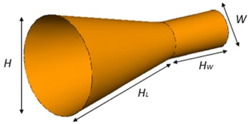
Figure 8: Conical feed horn structure.
Electromagnetic simulations are performed by using FEKO electromagnetics solver to validate the feed horn performance. The three-dimensional (3D) and one-dimensional (1D) radiation patterns are shown in Figs. 9 (a) and (b), respectively. The reflector edge level beam becomes -7.3 dB and -8.5 dB for E-plane and H-plane, respectively. In Fig. 3, 10dB edge level is achieved at =0.7. Then, at =0.62, the edge level is slightly increased. From Fig. 9 (b), the half power beam-width, , of the E-plane becomes =46 (0.8 rad). From Table 3, /H becomes 0.67 m. Then, and /H relation is given by the following equation:
| (14) |
By comparing equation (14) and equation (4), adequacy of 1.2 is ensured.
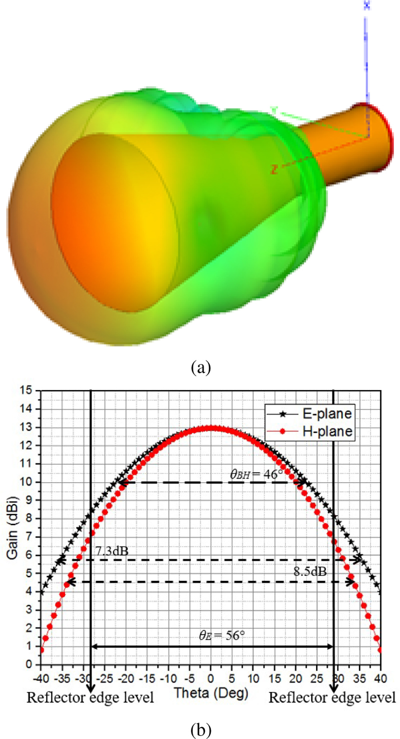
Figure 9: (a) 3D radiation pattern of a single 7.5 GHz horn antenna and (b) E-plane and H-plane radiation pattern of a single horn.
C. Horn mutual coupling
Two horns are closely arranged to calculate the mutual coupling of the feed horn arrangement, as shown in Fig. 10. In general, the mutual coupling of two horn excitations is the superposition of one horn excitation. The mutual coupling can be evaluated by the situation in which one horn of the two is excited. In Figs. 11 (a) and (b), electric field distribution and field intensity are shown, respectively. Field strength is decreased by more than 20 dB at the parasitic horn compared to the excited horn. Based on this observation, the effect of mutual coupling can be judged to be very small. The radiation pattern of a single horn compared to the dual horn configuration shown in Fig. 10 is plotted. Based on Fig. 12, no efficiency degradation between these two horn types is observed.
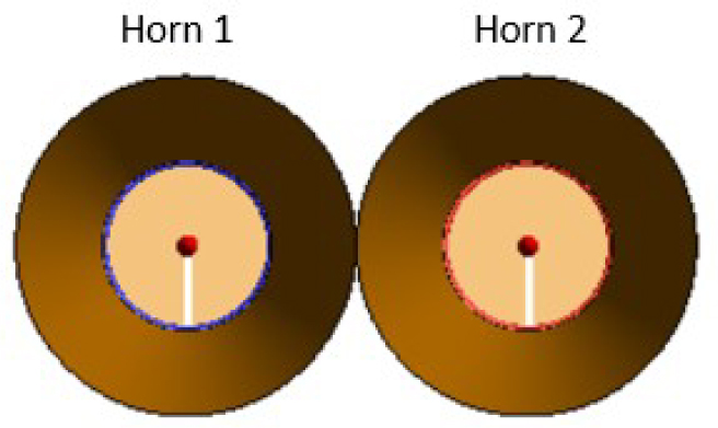
Figure 10: Dual horn configuration.
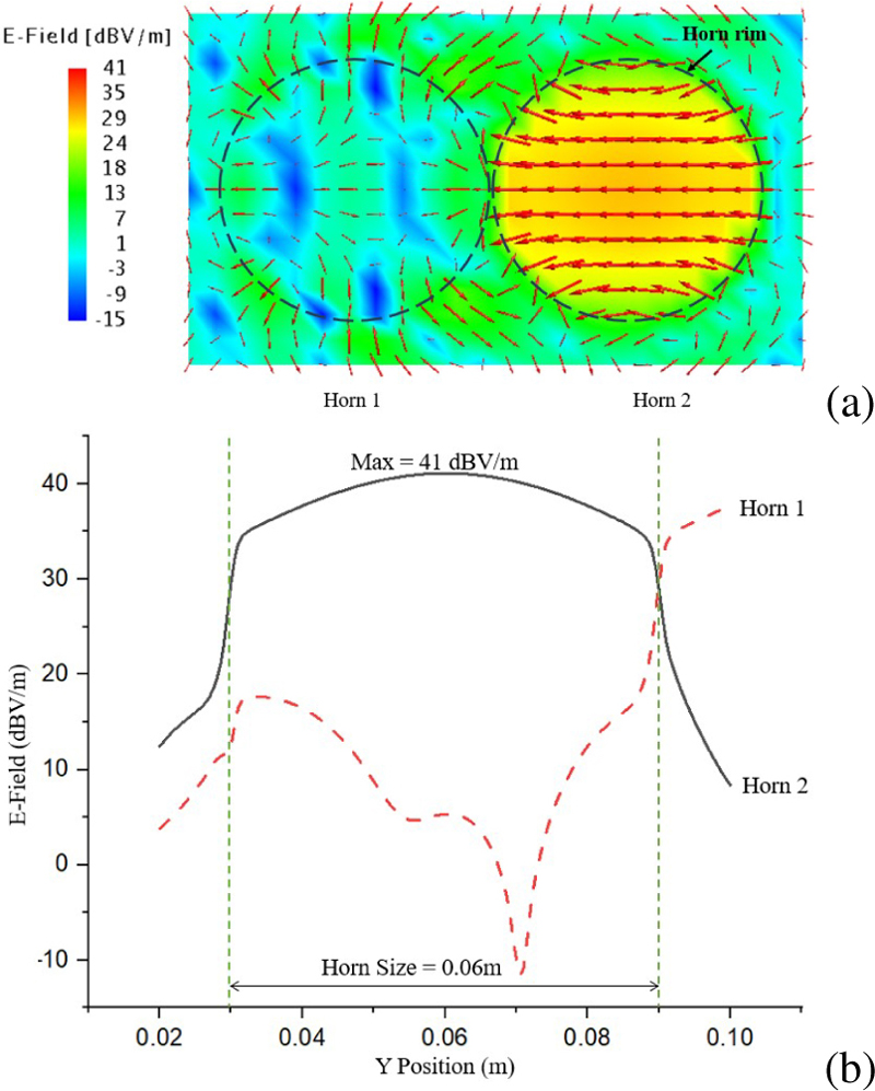
Figure 11: (a) Electric field distribution and (b) Field intensity.
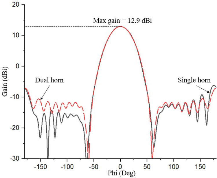
Figure 12: Radiation patterns of single and dual horn cases.
D. Horn allocation for multi-beam
The coordinate system for positioning the feed horn is shown in Fig. 13, where represents the angle from the centre to the desired beam position shown in Fig. 7. has two position components, known as and , that correspond to the feed horn displacement (). has three positional components: , and .
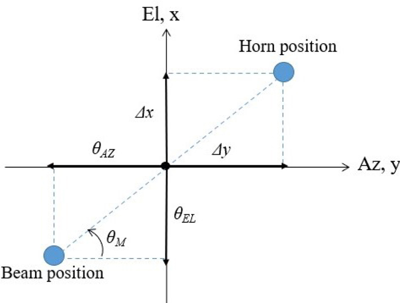
Figure 13: Design concept of feed horn allocation.
Table 3: Feed position for multi beam
| Beam | Beam Position | Feed Position | |||
|---|---|---|---|---|---|
| () | () | (m) | (m) | (m) | |
| B1 | -1.35 | 0.03 | 0.311 | -0.007 | -0.007 |
| B2 | -1.30 | -0.29 | 0.307 | 0.068 | -0.007 |
| B3 | -1.03 | -0.42 | 0.243 | 0.099 | -0.004 |
| B4 | -0.84 | -0.75 | 0.207 | 0.161 | -0.003 |
| B5 | -1.05 | -0.10 | 0.268 | 0.023 | -0.004 |
Using equations (7) and (8), the feed displacement, , can be expressed as:
| (15) |
Here, the components in terms of and are determined from the components. However, the feed displacement of and can only show a one-dimensional (1D) beam direction. In order to obtain the two-dimensional (2D) beam plot, the distances from the centre of the reflector to the caustic point can be estimated by the following equation, as described in [12]:
| (16) |
where
| (17) |
For the practical multi-beam allocations shown in Fig. 7, the corresponding feed positions are determined by equations (15), (16) and (17). Through calculation, the resulting beam and feed positions are summarized in Table 3. Based on the optimization of parameters in section II, all horns are arranged well without horn overlapping. Figure 14 shows the calculated feed horn arrangement for five beams.

Figure 14: Non-overlapping feed horn arrangement for five beams.
E. ANTENNA RADIATION PATTERN
The antenna configuration used in the electromagnetic simulations is shown in Fig. 15. The antenna parameters are assigned based on the values shown in Table 2 and the simulation parameters are summarized in Table 4. Method-of-Moments (MoM) technique was used to calculate the performance of feed horns and Large Element-Physical Optic (LE-PO) technique was applied to the parabolic reflector. For the case of five horn excitations, computer memory of 48.63 GB was utilized and the computation time was 142.25 hours.
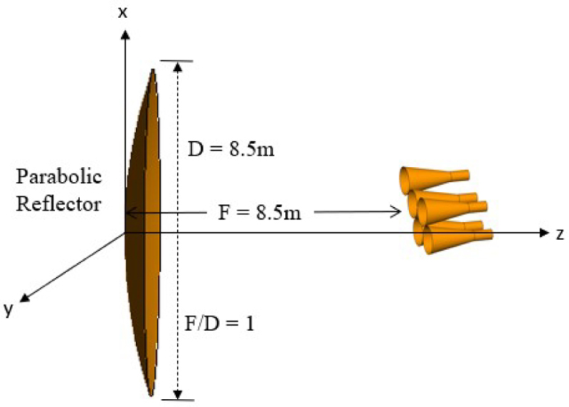
Figure 15: Antenna configuration used in electromagnetic simulations.
Table 4: Simulation parameters used for the electromagnetic simulations
| Item | Parameters | Details |
|---|---|---|
| Computer | Memory (RAM) | 128 GB |
| Clock time | 1.8 GHz | |
| Simulator | FEKO | |
| Simulation method | Reflector | LE-PO |
| Feed Horn | MoM | |
| Radiation Pattern | PO | |
| Total radiation pattern | PO | |
| Calculation process | Simulation memory | 48.63 GB |
| Simulation time | 142.25 H |
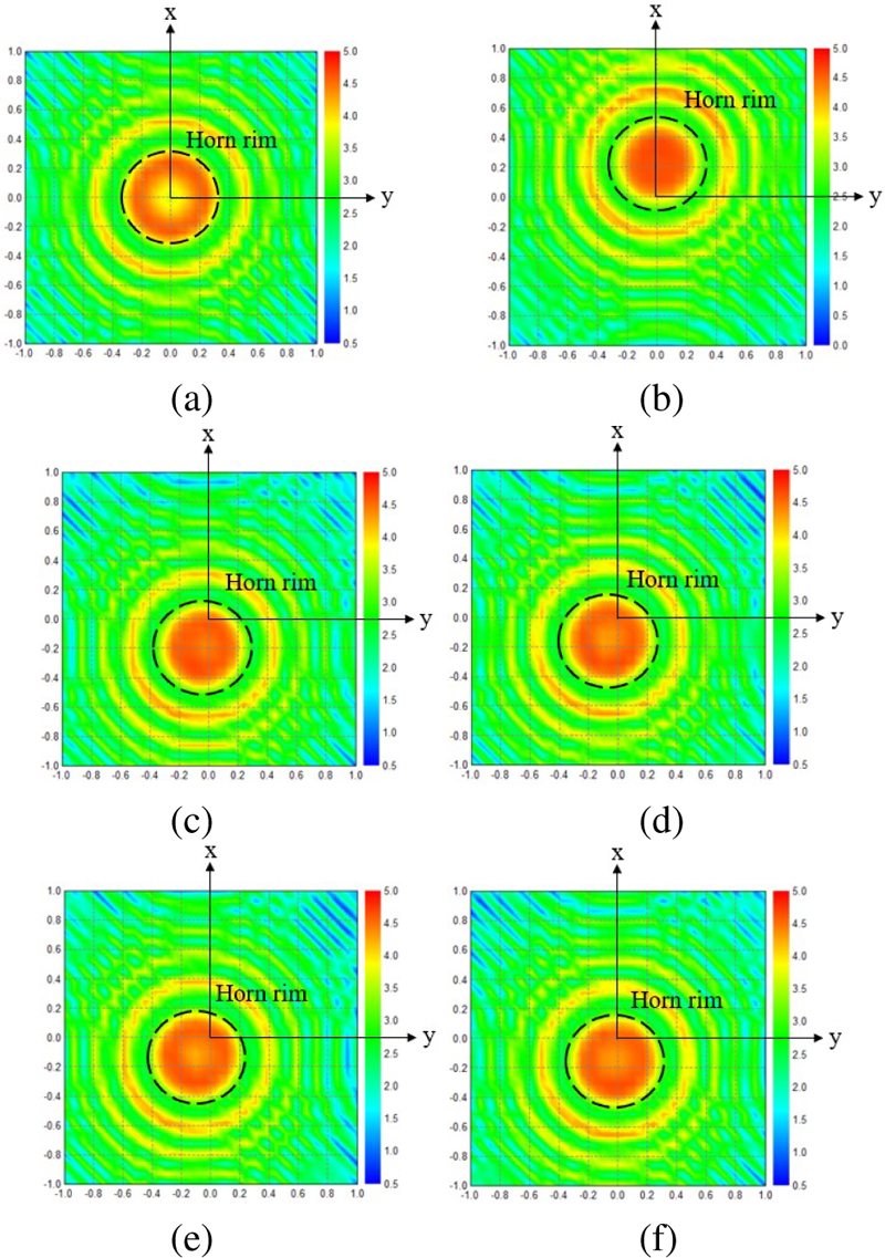
Figure 16: (a) Aperture distribution for B0, (b) Aperture distribution for B1, (c) Aperture distribution for B2, (d) Aperture distribution for B3, (e) Aperture distribution for B4, and (f) Aperture distribution for B5.
Figure 16 shows the electric near-field amplitude distribution (V/m) calculated using FEKO simulator on the active region which is 75 between the radiating element aperture and the reflector. By observing the distribution, the on-focus near-field pattern, which is at (0,0) is demonstrated in Fig. 16 (a). Meanwhile, Figs. 16 (b) to (f) show the electric near-field pattern when the feed position is shifted from the centre position at (0,0) for beams B1 to B5.
A two-dimensional (2D) calculated radiation pattern for Beam 1 (B1) and other beam allocations is shown in Fig. 17. B2 and B5 exist near the main lobe of B1, while other beams such as B3 and B4 are located in the side lobe area of B1. Each beam is connected at the beam separation angle, =1.3, where is the -3 dB beam width of the reflector with a value of 0.3. which is the beam separation corresponds to 0.39 and the crossover level becomes -6 dB from the peak level.
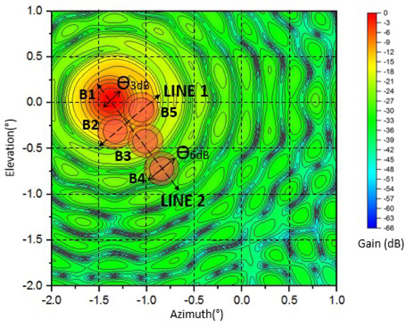
Figure 17: Radiation pattern of B1 to B5 plotted individually in elevation and azimuth plane.
To validate the beam relations, the one-dimensional (1D) radiation patterns are calculated for Line 1 and Line 2 in Fig. 18. Figure 19 shows the radiation pattern generated for Line 1 at the azimuth plane, illustrating the cross-over point between B2 and B5 beam where the radiation level is reduced by -6 dB from the peak level with =0.39.
Figure 19 shows the radiation pattern generated for Line 2 at the elevation plane. The cross-over level of B3 and B4 becomes -6 dB from the peak level with =0.39. The beam shapes of the main lobe and side lobes become almost the same for B1, B3 and B4 with small deformation and gain reduction.
Finally, the antenna configuration depicted in Fig. 15 has successfully produced a contoured beam to cover Peninsular Malaysia as illustrated in Fig. 20. The design utilized five feed horns, each with identical amplitude and phase excitation coefficients to maximize the radiation towards the coverage area. The contoured beam achieved almost uniform amplitude distribution within the contour, and the Peninsular Malaysia shape is well-covered, as illustrated in Figs. 7, 4 and 17. This validates the adequateness of the contoured beam that was achieved using ‘no overlapping feed’ arrangement.
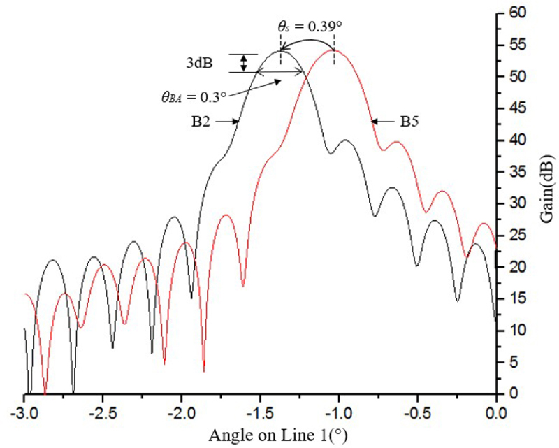
Figure 18: Radiation patterns of B2 and B5 on the Line 1.
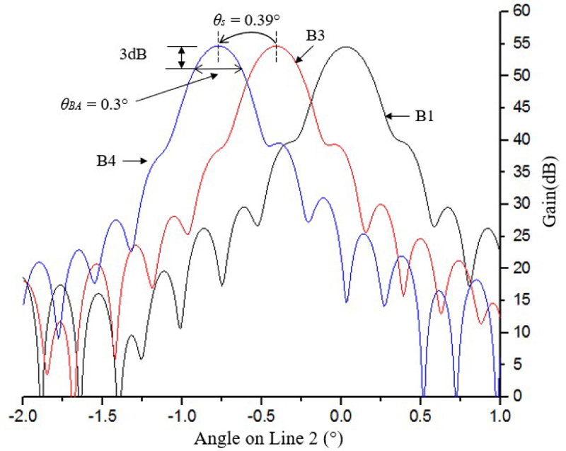
Figure 19: Radiation patterns on B1, B3 and B4 on the Line 2.
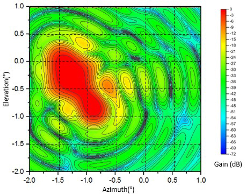
Figure 20: Contoured beam of Peninsular Malaysiashaped.
IV. BENCHMARKING OF PRIOR RESEARCH
Previous researchers have done similar works on using multi-feed, as summarized in Table 5. Previously, feed overlapping problems or different horn sizes were shown. However, more positive trials have been developed in this paper to avoid feed overlapping.
In this paper, we proposed a useful design chart as shown in Fig. 6 that compromised equations (6), (9) and (10) that determine the feed displacement, d, horn size, H, and beam separation, . These three parameters are crucial in preventing feed overlapping. It demonstrates that the d/H value represents the judging value in mitigating overlapped horns. This value of d/H was directly proportional to , where when d/H increased, also increased, allowing feed overlapping and redundancy of beams to be omitted.
Table 5: Comparison of the proposed technique for multi-beam antenna for contour beam shape
| Ref. | Method | Description |
|---|---|---|
| [17] | Malaysian coverage using rectangular horn and array feed. | Rectangular horn overlapping for Malaysian coverage. |
| [18] | Beam coverage was synthesized based on beam amplitude and phase excitation only. | Feed is not considered. |
| [19] | To reduce feed size, small lens is attached at the surface of the horn. | Mutual coupling between adjacent horn is not discussed due to different frequency use. |
| [20] | Caribbean region coverage of Brasilsat satellite is achieved by combination of many sizes rectangular horns. | Horn overlapping escaped by employing different size of horns. |
| This paper | The design chart for optimisation of beam position and feed horn size is derived. | No overlapping feed horn with the same size is obtained for Malaysia beam coverage |
V. CONCLUSION
In this study, a method to prevent feed horn overlapping in a parabolic reflector antenna system has been proposed. To demonstrate the accuracy of the proposed method, a practical case of Malaysia contour beam design by a combination of five beams is shown. A universal design chart for feed horn sizes at many antenna configurations has been developed and, based on this design chart, the correlation between and to the beam separation and horn size has been derived for no feed overlapping condition in the reflector system design. To ensure the practicality and accuracy of this design chart, a Peninsular Malaysia coverage beam antenna has been designed where the multi-beam allocations and feed horn allocations are obtained. The validity of the technique has been shown through the simulation results of the non-overlapping condition of the horn arrangement. Furthermore, the radiation beam produced for the targeted beam position is excellent, which indicates that the beam position design is accurate. The final Malaysia beam coverage obtained through the arrangement of five multi beams shows good agreement with the geographical shape of Malaysia, ensuring an excellent contour beam for Peninsular Malaysia. Overall, the proposed method has been shown to be practical and effective in mitigating feed horn overlapping in parabolic reflector antenna systems, paving the way for improved antenna system design and performance.
ACKNOWLEDGMENT
This work was supported by Universiti Teknologi MARA and Ministry of Higher Education (MOHE) for funding under the Prototype Development Research Grant Scheme (PRGS) 600-RMC/PRGS 5/3 (001/2022).
REFERENCES
[1] measat.com. [2022, July 22]. MEASAT [Online]. Available: http://www.measat.com/wp-content/uploads/2020/10/MEASAT-3d. 2022.
[2] R. C. Gupta, S. K. Sagi, K. P. Raja, N. K. Sharma, and R. Jyoti, “Shaped prime-focus reflector antenna for satellite communication,” IEEE Antennas and Wireless Propagation Letters, vol. 16, pp. 1945-1948, Mar. 2017.
[3] M. Maharajan, R. Jyoti, K. Sood, and S. B. Sharma, “A method of generating simultaneous contoured and pencil beams from single shaped reflector antenna,” IEEE Transaction on Antennas Propagation, vol. 61, no. 10, pp. 5297-5301, Oct. 2013.
[4] W. Bornemann, P. Balling, and W. English, “Synthesis of spacecraft array antennas for intelsat frequency reuse multiple contoured beams,” IEEE Transaction on Antennas Propagation, vol. 33, no. 11, pp. 1186-1193, Nov. 1985.
[5] S. K. Rao, “Parametric design and analysis of multiple-beam reflector antennas for satellite communications,” IEEE Antennas and Propagation Magazine, vol. 45, no. 4, pp. 26-34, Aug. 2003.
[6] N. J. G. Froseca and J. Sombrin, “Multi-beam reflector antenna system combining beam hopping and size reduction of effectively used spots,” IEEE Antennas and Propagation Magazine, vol. 54, no. 2, pp. 88-99, Apr. 2012.
[7] K. S. Rao, G. A. Morin, M. Q. Tang, S. Richard, and K. K. Chan, ”Development of a 45 GHz multiple-beam antenna for military satellite communications,” IEEE Transactions on Antennas and Propagation, vol. 43, no. 10, pp. 1036-1047, Oct. 1995.
[8] E. R. Boudriau, “Multiple-beam antennas for military satellite communication systems,” Defence Research Establishment, Ottawa, Technical Note 95-1, 1995.
[9] N. H. Abd Rahman, M. T. Islam, N. Misran, Y. Yamada, and N. Michishita, ”Generating contoured beams for malaysia region by using a caustic locus graph [Antenna Applications Corner],” IEEE Antennas and Propagation Magazine, vol. 56, no. 6, pp. 328-336, Dec. 2014.
[10] J. Yahagi and M. Haneishi, ”A consideration on beam-shaping of microstrip array antenna,” in Symposium on Antenna Technology and Applied Electromagnetics [ANTEM 2000], Winnipeg, Man, pp. 447-450, 2000.
[11] H.-T. Chou, K.-H. Bai, C.-C. Sun, C.-T. Yu, and H.-T. Hsu, ”Design of multi-beam antenna array using tapered slot elements,” 2013 International Symposium on Electromagnetic Theory, pp. 863-865, July 2013.
[12] N. H. Abd Rahman, M. T. Islam, and Y. Yamada, “Design of shaped-beam parabolic reflector antenna for peninsular malaysia beam coverage, and its overlapping feed issues,” Applied Computational Electromagnetics Society (ACES) Journal, vol. 30, no. 9, pp. 952-958, Aug. 2015.
[13] T. Nurdan, T. Sonmez, and T. Fikret, “Influences of amplitude tapering and feed blockage on the radiation characteristics of Ku-band parabolic reflector antennas,” Applied Computational Electromagnetics Society (ACES) Journal, vol. 35, no. 3, pp. 322-330, Mar. 2020.
[14] W. L. Stunzman and G. A Thiele, Antenna Theory and Design, 3 ed. New Jersey: John Wiley & Sons Inc, p. 139, 2012.
[15] W. L. Stunzman and G. A Thiele, Antenna Theory and Design, 3 ed. New Jersey: John Wiley & Sons Inc, p. 409, 2012.
[16] C. A Balanis, Antenna Theory Analysis and Design, New Jersey: John Wiley & Sons Inc, p. 783, 2016.
[17] N. H. Abd Rahman, M. T. Ali, M. T. Islam, and Y. Yamada, “Design and performance improvement of shaped-beam parabolic reflector antenna for small region coverage by non-symmetrical array feed technique,” International Journal of Applied Electromagnetics and Mechanics, vol. 51, no. 3, pp. 307-318, Jan. 2016.
[18] I. Aryanian and M. H. Amini, “Synthesis of contoured beam multifeed reflector antenna for optimum coverage,” Microwave and Optical Technology Letters, vol. 63, no. 2, Feb. 2021.
[19] Z.-Y. Zhang, Y. Zhao, N.-W. Liu, L.-Y. Ji, S. Zuo, and G. Fu, ”Design of a dual-beam dual-polarized offset parabolic reflector antenna,” IEEE Transactions on Antennas and Propagation, vol. 67, no. 2, pp. 712-718, Feb. 2019.
[20] Y. T. Lo and S. W. Lee, Antenna Handbook: Theory, Applications, and Design. New York: Springer, pp. 15-80, 1993.
BIOGRAPHIES

Nur Faiqah Fauzi received the B.Eng. in Computer Engineering from the Universiti Teknikal Malaysia Melaka (UTeM) in 2009, and the M.Sc. in Telecommunication and Information Engineering from Universiti Teknologi MARA (UiTM) in 2012. Currently she is pursuing her Ph.D. in Universiti Teknologi MARA (UiTM). Her Ph.D. works was on analyzing and designing Satellite-mount antenna for Malaysia contoured shaped coverage. Her current research interests include array antennas, antennas for space application, RF and microwave design and electromagnetic analysis.

Nurul Huda Abd Rahman (M’15) received her M.Eng. degree in electronic from University of Surrey, Guildford, United Kingdom in 2008 and Ph.D. degree in electric, electronic and systems engineering from Universiti Kebangsaan Malaysia in 2014. She joined Astronautic Technology (M) Sdn. Bhd. as a Spacecraft Engineer in 2008, where she was involved in various small-class satellite development and R&D projects. In 2014, she joined Universiti Teknologi MARA Malaysia (UiTM) and has been working in the same university until now, where she currently holds the position of Associate Professor. She also received a 2-year Postdoctoral Fellowship under the Malaysia-Japan International Institute of Technology, Universiti Teknologi Malaysia between 2018-2019. Her current research interests include antennas for space and terrestrial applications, array antennas, reflector and lens antennas, wearable and flexible antennas, RF and microwave design, and electromagnetic analysis. She is the Professional Engineer of the Board of Engineers Malaysia (BEM) since 2019. She has been appointed as the Executive Committee of the IEEE Malaysia AP/MTT/EMC Joint Chapter for 2021-2022. She was also the recipient of the Best Professional Paper Award IEEE Malaysia Comsoc & VTS Joint Chapter in 2018 and the Best Paper Award from IEEE Malaysia AP/MTT/EMC Joint Chapter in 2018 and 2019.

Yoshihide Yamada received the bachelor’s and master’s degrees in Electronic Engineering from the Nagoya Institute of Technology, in 1971 and 1973, respectively, and the Ph.D. degree in electrical engineering from the Tokyo Institute of Technology, in 1989. He joined Electrical Communication Laboratories, Nippon Telegraph and Telephone Corporation (NTT) in 1973, and moved to NTT Mobile Communications Network, Inc. (NTT DoCoMo) in 1993. In 1998, he joined National Defense Academy as a Professor. In 2014, he joined the Malaysia-Japan International Institute of Technology, Universiti Teknologi Malaysia (UTM), Malaysia, as a Professor. His research interests are aperture antennas, array antennas, very small antennas, and radar cross sections. He is a fellow of IEICE Japan, a Senior Member of IEEE APS, and a member of ACES. He received the Excellent Paper Award and the Best Tutorial Paper Award from IEICE, in 2013 and 2014, respectively.

Robi’atun Adayiah Awang received the B.Eng. degree (Hons.) and M.Eng. Degree in computer & communication engineering from Universiti Kebangsaan Malaysia (UKM) in 2001 and 2005, respectively, and the Ph.D. degree from RMIT University, Melbourne, VIC, Australia, in 2016. She is currently a senior lecturer with Faculty of Electrical Engineering, Universiti Teknologi MARA (UiTM), Shah Alam, Malaysia. Her current research interests include antennas, microwave sensors and flexible and tunable electromagnetic devices. She has published several research papers in international peer-reviewed journals and proceedings.

Idnin Pasya become a member of IEEE in 2010. He received the B.E. and M.E. and Dr. Engineering degrees in Information and Communication Engineering from Tokyo Denki University in 2004, 2006 and 2015, respectively. He worked in Toshiba PC & Network, Tokyo, Japan, from 2006 to 2009 before joining the Faculty of Electrical Engineering, Universiti Teknologi MARA, Malaysia. His research interest include ultra wideband communication system, and MIMO radar and its application. He was the executive committee of Malaysia section IEEE AP/MTT/EMC joint chapter from 2017 to 2022. Dr. Idnin received the IEEE MTT Best Paper Award in 2014 IEEE Radio and Wireless Symposium. He joined University of Aizu in 2023 as an associate Professor.
ACES JOURNAL, Vol. 38, No. 12, 941–951
doi: 10.13052/2023.ACES.J.381203
© 2023 River Publishers