Compact Integrated Circular Polarization Filtering Antenna based on SIW Cavity
Qiyue Gao, Yuyao Zhu, Xinyu Yang, and Rui Li
1School of Electrical and Automation Engineering
Nanjing Normal University, Nanjing, 210046, China
2School of Electronic Science and Engineering
Jilin University, Changchun 130012, China
lirui202069@163.com
Corresponding Author
Submitted On: July 7, 2023; Accepted On: October 22, 2023
ABSTRACT
In this paper, a compact integrated circular polarization filtering antenna is proposed based on substrate integrated waveguide (SIW) cavity. Firstly, a dual-mode (TE and TE modes) rectangular cavity is utilized as a common feeding cavity to achieve a dual-mode filtering response. And then, an additional rectangular patch with a slot is coupled from the feeding cavity for circular polarization radiation. To verify the proposed concept, a prototype circular polarization filtering antenna is simulated. The circular polarized filtering antenna resonates at 4.225 GHz with a low cross-polarization and a high gain of 7.23 dBi.
Keywords: Circular polarization (CP), filtering antenna, patch antenna, substrate integrated waveguide (SIW).
I. INTRODUCTION
With the rapid development of wireless communication systems, the integration and miniaturization of RF front-end have attracted more and more attention. Filter and antenna, as two important components of the RF front-end, are often employed in cascaded form. However, the form not only generates harmonics but also causes the system to be bulky. Thus, it is significant to integrate filter [1] and antenna [2] into a single component with dual functions. A filtering antenna [3] combines an antenna and a filter. It can provide the conversion between electrical power and radio waves, as well as the shaping of a filter-like response to antenna gain and input return loss. The integration of antennas and filters has been proven to be an effective method to reduce the cost and function block size of microwave systems.
Some filtering antennas are designed using different transmission structures in [4–5]. In previous designs, their gain responses cannot be achieved well. In recent years, because the substrate integrated waveguide (SIW) structure can achieve the interconnection of passive and active devices. Therefore, it reduces the volume of the millimeter wave system and the cost. In addition, SIW have the merits of low insertion loss, high quality factor, and high-power capacity. Because of these advantages, the combination of SIW and filtering antenna is also attracting more and more attention.
Circularly polarized (CP) antennas have been widely investigated in recent years due to their advantages of suppressing interference and reducing polarization mismatch [6–7]. Only a few reports of CP filtering antennas have much room for improvement in bandwidth and miniaturization. In [8], by seamlessly integrating a high-Q SIW filter with a CP patch antenna, a planar CP filtering antenna is achieved. But the axial ratio (AR) bandwidth for the single antenna element is narrow, and a complicated rotated feeding network and an array are required to enhance the bandwidth. In [9], a novel single-fed low-profile CP antenna with a bandpass filtering response and a wider AR bandwidth is proposed. Although filtering response and wider AR bandwidth are achieved, the size of the presented antenna is still bulky. In addition, there are two perturbation modes on either side of the passband that affect the performance of the antenna.
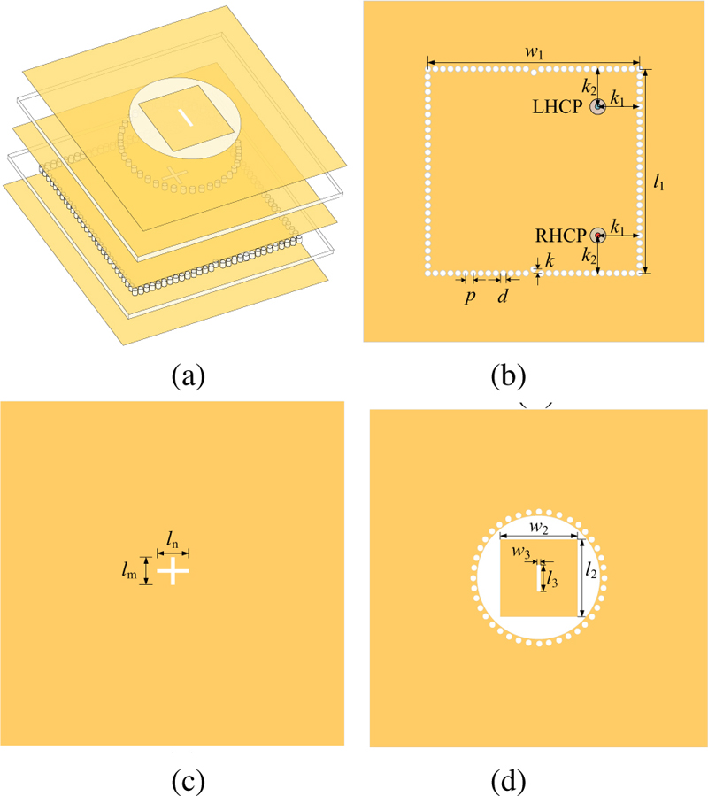
Figure 1: The structure of the proposed filtering antenna: (a) 3D-view, (b) bottom-layer view, (c) middle-layer view, and (d) top-layer view.
In this paper, a CP filtering antenna is proposed with a compact double-layer SIW structure. By exploiting the electric field distributions from a feeding cavity with two orthogonal modes and a coupled symmetry radiation patch, good AR bandwidth and low cross-polarization are well attained. The operating principles and design method will be extensively illustrated as follows.
II. DESIGN OF CIRCULAR POLARIZATION FILTERING ANTENNA
A. Circular polarization filtering antenna configuration
Figure 1 (a) shows the construction of the proposed circular filtering antenna. In the bottom layer, a rectangular cavity with a pair of orthogonal modes based on SIW is illustrated in Fig. 1 (b). And two metal via holes are placed in a particular position to control frequency. In Fig. 1 (c), two coupling apertures of the middle layer are used to transfer energy. As shown in Fig. 1 (d), a square patch with a slot is used to radiate circularly polarized beams. It is worth noting that the proposed design scheme can achieve a reverse circularly polarized beam by changing only the feed position without changing other parameters. The locations of the feed ports to achieve left- and right-handed CP are presented in Fig. 1 (b).
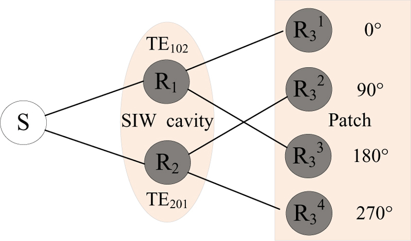
Figure 2: Coupling topology.
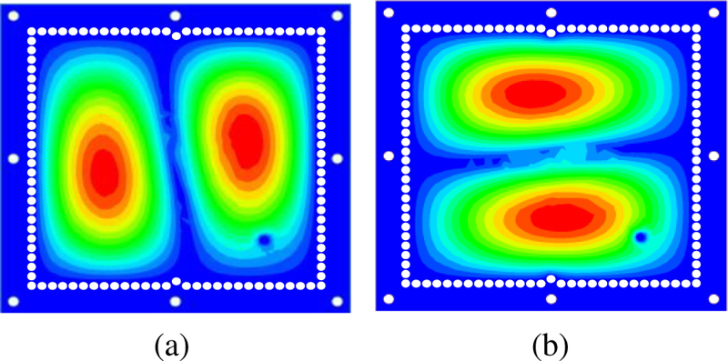
Figure 3: E-field distributions of the bottom square cavity: (a) TE mode and (b)TE mode.
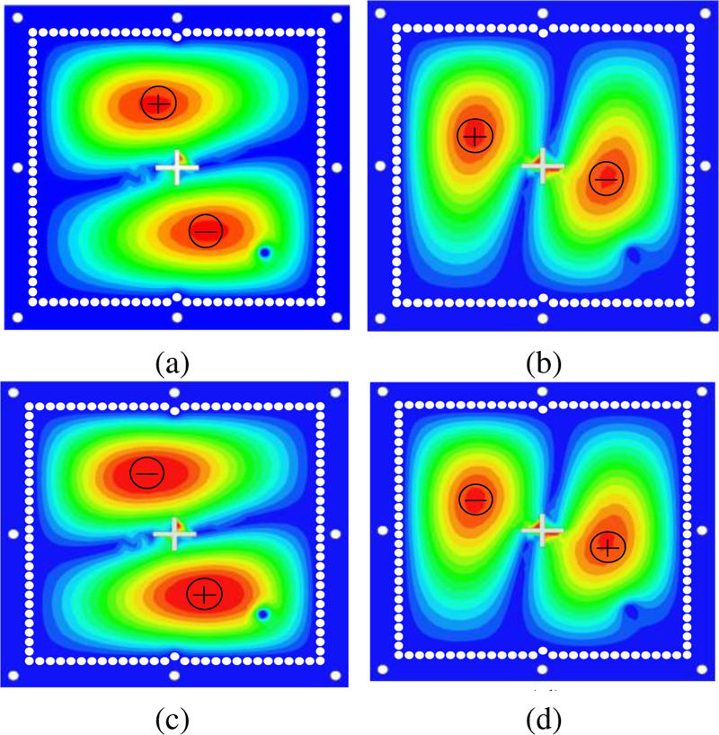
Figure 4: Electric field distributions within one period for middle metal layer: (a) t = 0, (b) t = T/4, (c) t = T/2, and (d) t = 3T/4.
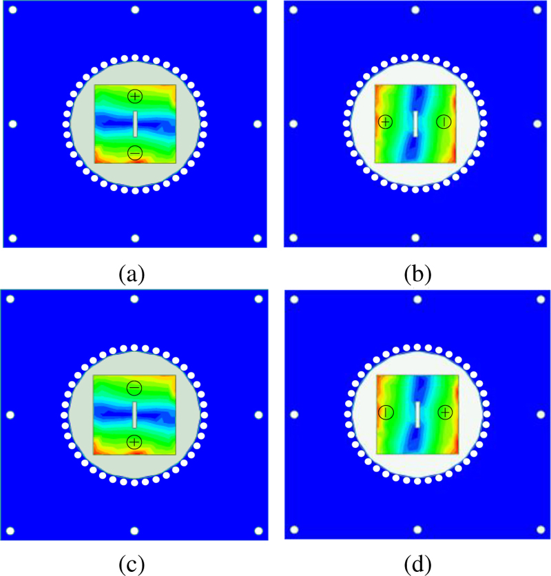
Figure 5: Electric field distributions within one period for top metal layer: (a) t = 0, (b) t = T/4, (c) t = T/2, and (d) t = 3T/4.
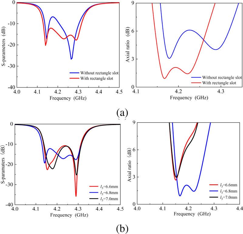
Figure 6: Simulated reflection coefficient (left) and AR (right) for the proposed CP filtering antenna for different conditions: (a) with and without rectangle slot and (b) by varying l.
B. Operating principles
In order to explain the operating principles of the proposed circular polarization filtering antenna, a coupling topology corresponding to the configuration is described, as shown in Fig. 2. R and R represent TE mode and TE mode, respectively. R1 3, R2 3, R3 3, and R4 3 represent TM, TM, TM, and TM mode, respectively. A progressive phase difference of 90 in sequence among the four radiation modes is obtained. Circles represent resonant modes and input sources/ radiating load, and lines represent coupling between them. In addition, in Fig. 3, the two orthogonal modes of TE mode and TE mode would be coupled electrically with each other, which exhibits a phase difference of 90. To further explain the CP radiation, the vector electric field distribution of the proposed right-handed CP antenna is presented in Figs. 4 and 5 for different phase stages. As shown in Fig. 4, the electric field inside the SIW cavity rotates counterclockwise within one period. Similarly, within one period, TM mode and TM mode of the patch can be transformed into each other and rotated counterclockwise, as shown in Fig. 5. Therefore, the proposed antenna structure can radiate right-handed CP beams. In addition, a rectangular slot is introduced at the center of the patch to optimize the impedance matching and AR bandwidth. Simulated reflection coefficient and AR of the proposed circulation polarization filtering antenna with different conditions are shown in Fig. 6. By removing the slot of the patch and fine-tuning the antenna size, it is found that the simulated impedance matching and AR become worse, as shown in Fig. 6 (a). And the effects of the length of the slot etched into the patch on the antenna reflection coefficient and axial ratio are studied in Fig. 6 (b). It can be found that the length of the slot has a slight influence on the reflection coefficient of the antenna and can obviously improve the AR of the antenna.
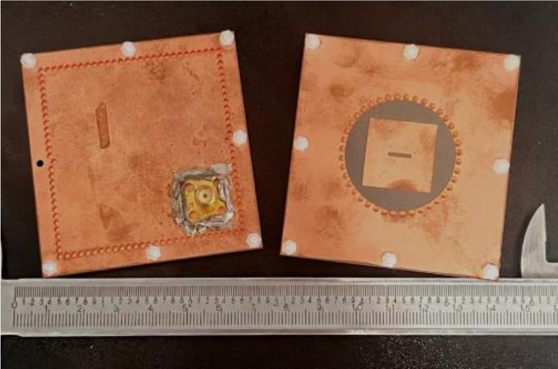
Figure 7: The photograph of the fabricated prototype.
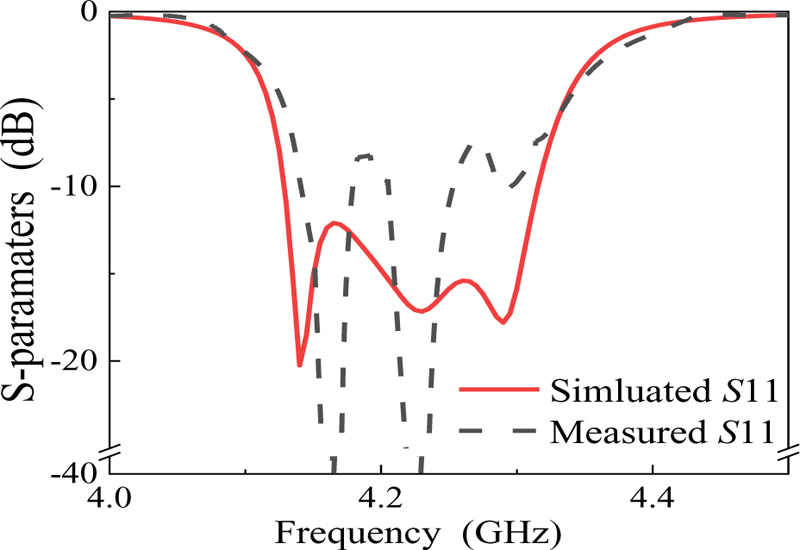
Figure 8: Simulated and measured results for the proposed right-handed CP filtering antenna.
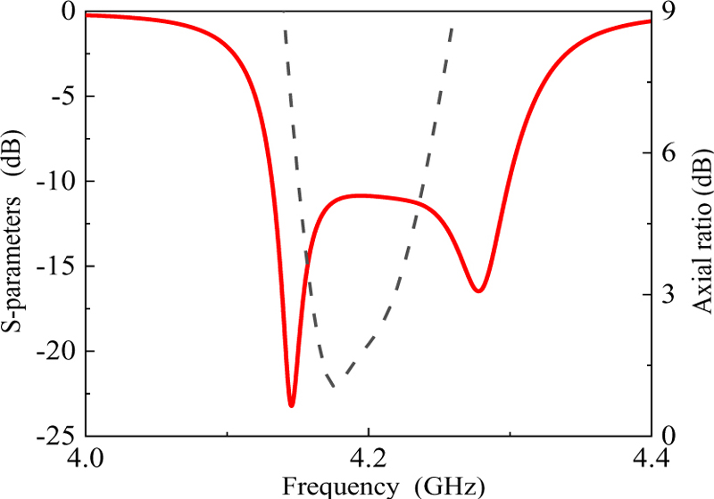
Figure 9: The reflection coefficient and AR of the proposed left-handed CP filtering antenna.
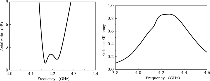
Figure 10: The AR (left) and the radiation efficiency (right) of the proposed right-handed CP filtering antenna.
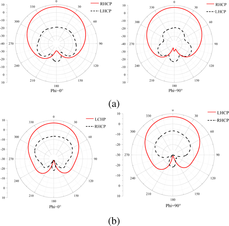
Figure 11: The radiation patterns for the proposed CP filtering antenna: (a) Right-handed CP filtering antenna and (b) left-handed CP filtering antenna.
III. IMPLEMENTATION AND RESULTS
For experimental validation, a compact right-handed CP filtering antenna is designed, prototyped, and tested. The photograph of the prototype is shown in Fig. 7. The CP filtering antennas are designed on Rogers Duroid 5880 substrate with the relative dielectric constant of 2.2 and loss tangent of 0.001, and the thickness h = 1.58 mm. The dimensions of the proposed filtering antenna are eventually determined as follows: w = 56 mm, l = 54 mm, p = 2 mm, d = 1.6 mm, k = 1 mm, k = 11 mm, k = 10 mm, l = 8.4 mm, l = 7.2 mm, l = 20.6 mm, w = 20.6 mm, w = 1m m, l = 6.8 mm.
The measured reflection coefficients are presented in Fig. 8. The 10-dB fractional bandwidth is 4.5%. Figure 10 shows that the fractional AR bandwidth of the right-handed CP filtering antenna is 2.2% and the radiation efficiency is better than 86%. In order to validate the feasiblility of the proposed design method, the left-handed CP filtering antenna is designed by only changing the feed position of the antenna without changing other parameters. The simulated reflection coefficients and the AR are presented in Fig. 9. It is obvious that it has 4.1% fractional bandwidth and 1.5% AR bandwidth.
Figure 11 shows the radiation patterns of the proposed right-and left-handed CP filtering antenna at 4.225 GHz. As observed, the cross-polarizations are better than 23 dB at 4.225 GHz for the right-handed circular polarization filtering antenna. The gain is better than 7.34 dBi in the right-handed circularization filtering antenna and is better than 7.1 dBi in the left-handed CP filtering antenna. The radiation patterns show that the proposed circular polarization filtering antenna has good polarization purity for right- and left-handed CP filtering antennas. The developed antenna is compared with the previously reported antenna in Table 1. The proposed filtering antenna performs to advantage in terms of relatively wider AR bandwidth and competitive gain as well as compact size.
Table 1: Comparison with related antennas
| Reference | Filtering Response | AR (%) | Gain (dBi) | Size () |
| [10] | No | 1.1 | 5.0 | 1.96*1.01 |
| [11] | No | 1.0 | 9.2 | 1.33*1.33 |
| [12] | Yes | 8.8 | 5.8 | 1.07*1.07 |
| [13] | Yes | 4.9 | 5.1 | 0.89*0.89 |
| [8] | Yes | 1.3 | 6.8 | 0.56*0.44 |
| [9] | Yes | 3.9 | 8.0 | 1.01*1.01 |
| Our work | Yes | 2.2 | 7.4 | 0.84*0.92 |
IV. CONCLUSION
In this paper, a compact integrated CP filtering antenna is proposed with good filtering and polarization purity based on a dual-mode SIW cavity. It is believed that the proposed design with these advantages will have the opportunity to be used in future wireless communication systems.
ACKNOWLEDGMENT
This work was supported in part by the Postgraduate Research and Practice Innovation Program of Jiangsu Province under Grant KYCX23_1763. (Corresponding author: Rui Li)
REFERENCES
[1] G. Zhang, Y. Liu, E. Wang, and J. Yang, “Multilayer packaging siw three-way filtering power divider with adjustable power division,” IEEE Trans. Circuits and Syst. II, Exp. Briefs, vol. 67, no. 12, pp. 3003-3007, Dec. 2020.
[2] L. Zhu and N. Liu, “Multimode resonator technique in antennas: A review,” Electromagnetic Science, vol. 1, no.1, pp. 1-17, Mar. 2023.
[3] H. Chu, C. Jin, J. Chen, and Y. Guo, “A 3-D millimeter-wave filtering antenna with high selectivity and low cross-polarization,” IEEE Trans. Antennas Propagat., vol. 63, no. 5, pp. 2375-2380, May 2015.
[4] A. Abbaspour-Tamijani, J. Rizk, and G. Rebeiz, “Integration of filters and microstrip antennas,” IEEE Int. Antennas Propag. Symp. Dig., vol. 2, pp. 874–877, June 2002.
[5] W. Wu, Y. Yin, S. Zuo, Z. Zhang, and J. Xie, “A new compact filter-antenna for modern wireless communication systems,” IEEE Antennas Wireless Propag. Lett., vol. 10, pp. 1131-1134, 2011.
[6] S. A. Razavi and M. H. Neshati, “A low profile, broadband linearly and circularly polarized cavity backed antenna using halved-dual mode SIW cavity,” Applied Computational Electromagnetics Society (ACES) Journal, vol. 31, no. 8, pp. 953-959, Aug. 2016.
[7] F. Azamian, M. Naghi Azarmanesh, and C. Ghobadi, “A novel compact CPW-fed antenna with circular polarization characteristics for UWB applications,” Applied Computational Electromagnetics Society (ACES) Journal, vol. 30, no. 1, pp. 93-98, Jan. 2015.
[8] T. Li and X. Gong, “Vertical integration of high-Q filter with circularly polarized patch antenna with enhanced impedance-axial ratio bandwidth,” IEEE Trans. Microw. Theory Techn., vol. 66, no. 6, pp. 3119-3128, June 2018.
[9] S. Ji, Y. Dong, Y. Pan, Y. Zhu, and Y. Fan, “Planar circularly polarized antenna with bandpass filtering response based on dual-mode SIW cavity,” IEEE Trans. Antennas Propagat., vol. 69, no. 6, pp. 3119-3128, June 2021.
[10] Q. Wu, J. Yin, C. Yu, H. Wang, and W. Hong, “Low-profile millimeter wave SIW cavity-backed dual-band circularly polarized antenna,” IEEE Trans. Antennas Propagat., vol. 65, no. 12, pp. 7310-7315, Dec. 2017.
[11] Z. C. Hao, X. M. Liu, X. P. Huo, and K. K Fan, “Planar high-gain circularly polarized element antenna for array applications,” IEEE Trans. Antennas Propagat., vol. 63, no. 5, pp. 1937-1948, May 2015.
[12] Q. S. Wu, X. Zhang, and L. Zhu, “Co-design of a wideband circularly polarized filtering patch antenna with three minima in axial ratio response,” IEEE Trans. Antennas Propagat., vol. 66, no. 10, pp. 5022-5030, Oct. 2018.
[13] Y. T. Liu, K. W. Leung, J. Ren, and Y. X. Sun, “Linearly and circularly polarized filtering dielectric resonator antennas,” IEEE Trans. Antennas Propagat., vol. 67, no. 6, pp. 3629-3640, June 2019.
BIOGRAPHIES

Qiyue Gao was born in Jiangsu, China, in 2003. She is currently pursuing the B.E. degree in electrical engineering and automation at Nanjing Normal University (NNU), Nanjing, China. Her current research interests include multifunctional microwave passive circuits and antennas.

Yuyao Zhu was born in Jiangsu, China, in 2004. She is currently pursuing the B.E. degree in electrical engineering and automation at Nanjing Normal University (NNU), Nanjing, China. Her current research interests include multifunctional microwave passive circuits and antennas.

Xinyu Yang was born in Anhui, China, in 1997. She received the B.E. degree from the Shanghai Maritime University (SMU), Shanghai, China, in 2019. She is currently pursuing the M.E. degree at Nanjing Normal University, Nanjing, China. Her current research interests include microwave/millimeter-wave circuits and antennas.

Rui Li was born in Jiangsu, China, in 1996. He received the M.E. degree from the Nanjing Normal University (NNU), Nanjing, China, in 2023. He is currently pursuing the Ph.D. degree at Jilin University, Jilin, China. His current research interests include microwave/millimeter-wave circuits and antennas.
ACES JOURNAL, Vol. 38, No. 10, 756–760
doi: 10.13052/2023.ACES.J.381001
© 2023 River Publishers