A Numerical Analysis of Conformal Energy Selective Surface Array with Synthetic Functions Expansion
Ning Hu1, Yanlin Xu2, and Peiguo Liu2
1Information Engineering University, Zhengzhou 450001, China
1141832906@qq.com
2College of Electronic Science of National University of Defense Technology, Changsha 410073, China
13298656824@163.com, pg731@qq.com
Submitted On: July 23, 2023; Accepted On: March 18, 2024
ABSTRACT
Energy selective surface (ESS) is a special kind of metasurface with great potential in high-power microwave protection. In this paper, the electromagnetic (EM) properties of an ESS array are analyzed with synthetic functions expansion (SFX) method. A cylindrical conformal ESS array based on an I-shape element is designed for demonstration. The Bistatic RCS as well as electric field distribution of the ESS array is calculated with SFX and traditional full-wave numerical methods. The results show that SFX exhibits great advantages in memory cost while maintaining the same level of accuracy and efficiency with the multi-layer fast multipole method (MLFMM). Besides, the EM performance of the designed ESS is calculated with an array with finite elements and unit cell with periodic boundaries, respectively. The results show a good agreement. The proposed method can also be applied to the analysis of other kinds of metasurfaces whose elements share similar geometries with periodic or quasi-periodic arrangement. Especially for large-scale arrays, this method could well overcome the difficulty of balancing accuracy, efficiency, and resource consumption.
Index Terms: Energy selective surface (ESS), large-scale arrays, metasurface, method of moment (MoM), synthetic functions expansion (SFX).
I. INTRODUCTION
Energy selective surface (ESS) is a special kind of metasurface posing nonlinear transmission characteristics with respect to the field intensity of incident waves [1]. More specifically, ESS is supposed to be transparent to low-power microwaves but shield high-power microwaves adaptively. Therefore, ESS is regarded as a potential method in the fields of high-power microwave protection [2].
In the past several years, ESS has attracted great interest and significant progresses have been made [3–8]. In terms of the analytical and numerical modeling of ESS, an approximation method based on periodic boundary conditions is mostly adopted. In that case, ESS is regarded as an infinite array and its electromagnetic (EM) properties are obtained using Floquet model analysis [6]. However, this method is not valid for finite and conformal arrays [7]. On the one hand, the edge effects of a finite array should be taken into account. On the other hand, for most conformal arrays, they do not strictly satisfy the periodic boundary conditions. Thinking of this, full-wave numerical methods are usually adopted to simulate the EM properties of a finite conformal ESS array.
Nevertheless, traditional full-wave algorithms face several difficulties such as a tremendous cost of memory, low computational efficiency, and so on, when applied to large-scale arrays. For instance, method of moment (MoM) is a classic frequency-domain full-wave numerical method which is well known for high accuracy and pretty good adaptability for arbitrary 3D objects. When it comes to large-scale arrays, MoM requires significant memory cost which is usually unbearable for a single PC because of the complex dense matrix equations. Furthermore, the computational complexity is terrible. In contrast, time-domain full-wave numerical methods like finite difference time domain (FDTD) and finite integration technique (FIT) perform better than frequency-domain methods in memory consumption and computational efficiency in general. As a tradeoff, computational accuracy of time-domain methods is usually less than frequency-domain methods. Hence, for the modeling and analysis of large-scale conformal ESS arrays, an efficient and accurate full-wave numerical method is what we desire [9–12].
In this paper, an improved method of MoM called synthetic functions expansion (SFX) is used to analyze the EM properties of a large-scale cylindrical conformal ESS array. SFX is first presented by Matekovits et al., the core idea of which is using synthetic functions instead of low order basis functions to discretize EM integral equations [13–14]. After that, several meaningful works on SFX have been published which mainly focus on the following topics such as the construction of synthetic functions [15–16], the unsolved integral equations [17–18], and the parallel algorithm [12]. Compared to traditional full-wave numerical methods, the advantages of SFX are:
1) Since synthetic functions are adopted to discretize the integral equations, memory cost and efficiency of SFX will perform much better than MoM.
2) For an ESS array, synthetic functions defined on different elements can be reused because of the geometrical similarity between these elements. This feature is of vital importance in the analysis of large-scale arrays which can improve the computational efficiency greatly.
3) For a cylindrical conformal array, SFX only needs to mesh the surface of objects rather than the total space which means the memory cost of SFX will be less than traditional time-domain numerical methods.
The paper is arranged as follows. In Section II, a cylindrical conformal ESS array working at 10 GHz is designed and analyzed based on periodic boundary conditions. In Section III, we introduce the basic theory of SFX, then the modeling of ESS and the construction of synthetic functions are discussed. In Section IV, Bistatic RCS, electric field distribution, and high-power microwave protection performance of the designed cylindrical conformal ESS array are calculated using SFX and other numerical methods. Furthermore, the computational performance are discussed, from which we can see that SFX exhibits great advantages in memory consumption while maintaining the same level of computational accuracy and efficiency compared to traditional full-wave numerical methods.
II. MODEL DESIGN
For demonstration, a cylindrical conformal ESS array is designed and analyzed, and the detailed geometry parameters are shown in Fig. 1. The array includes 21*10=210 unit cells covering an azimuth angle of 180. The radius of the conformal array is 1.27 (=30 mm at 10 GHz) and the height is about 2. The unit cell is composed of an I-shaped metal structure with two diodes loaded on the vertical arm.
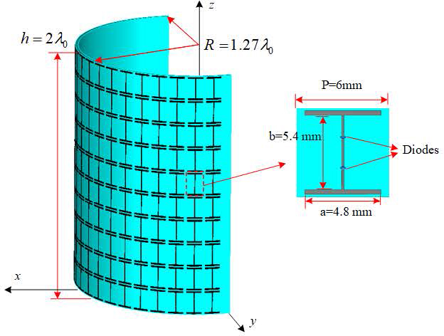
Figure 1: Illustration of the cylindrical conformal ESS array.
Transmission properties of the unit cell, shown in Fig. 2, are obtained with a commercial full-wave software (CST MWS 2021) under periodic boundary conditions where diodes are modeled as lumped elements, namely, a capacitor C=0.018pf and a resistor R=2for OFF and ON states, respectively [4]. It is not difficult to see that the transmission coefficient is near to 0 dB and smaller than -20 dB at the central frequency (10 GHz) when the diodes are in different states. The physical mechanism may be illustrated briefly by the shift of the resonance frequency. When the diodes are OFF under low-power EM waves, the resonance frequency is much higher than 10 GHz and the structure is supposed to be transparent to low-power EM waves. By contrast, when the structure is illuminated by high-power EM waves, the diodes will be triggered on by the induced voltage, and the ESS structure will resonate at 10 GHz. Then, the high-power EM waves will be reflected. By this way, electronic equipment in the area enclosed by the ESS array is able to receive low-power EM waves, which is the working signals. Meanwhile, high power EM waves are shielded by the ESS array adaptively to protect the electronic equipment.
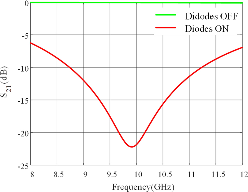
Figure 2: The transmission properties of the unit cell of ESS under periodic boundary condition.
In this work, our focus is not on the design method of the ESS structure or the underlined mechanism. We aim at the fast and accurate numerical analysis of a designed ESS array. In previous works, the performance of ESS is mainly evaluated by two important indexes - the insertion loss (IL) and the shielding effectiveness (SE) - which are defined as the transmission coefficient of the ESS under different states (Diodes OFF for IL and Diodes ON for SE). However, the transmission coefficients used in these definitions are obtained from an infinite array with periodic boundary conditions, which only illustrate an ideal situation. Thus, from a more practical perspective, we define the IL/SE as the average attenuation of the electric field in the area enclosed by the ESS array in different states. In more detail, IL and SE are defined as:
| (1) |
where S is the area enclosed by ESS array; and indicate the electric field with and without ESS array. In this paper, considering the ESS array is half-open, we select a semi-circle S in the transverse (to z) plane at z=30 mm as the area to calculate IL and SE. That is:
| (2) |
III. SFX ANALYSIS
A. Theory
Since SFX is an improved approach of MoM, we will begin with a brief introduction of MoM and the electric field integral equation (EFIE) is adopted for example.
Usually, EFIE can be compactly written as:
| (3) |
where and are the surface current and a unit vector, respectively. For a vector X (circled by S), L is the electric integral operator and defined as:
| (4) |
where ,and k are the frequency, the permeability, and the wave number in the free space, respectively. In addition, g is the Green’s function in the free space.
To solve the vector integral equation using MoM, we first need to use Rao-Wilton-Glisson (RWG) functions to discretize the unknown vector J and then to make Galerkin test. Then, (3) can be transformed into a linear scalar matrix equation as:
| (5) |
where Z is the impedance matrix, V is the excitation vector, and I is the current coefficient vector of basis functions.
Elements in Z and V can be calculated as:
| (6) |
where f and f are the basis functions (RWG functions in general), E stands for the electric field of the incident wave, A, B represents the inner product of A and B.
Different with the case in MoM, synthetic functions are used in SFX to discretize the surface current J and to make Galerkin test which will yield the following linear scalar matrix equation, as shown in the following term [19]:
| (7) |
where [P] and [Y] are expansion coefficients and current coefficients of synthetic functions; [Z] and [V] are impedance matrix and exciting matrix of the traditional MoM.
From (7) we can see that impedance matrix [W] and exciting matrix [G] of SFX can be got on the basis of [Z] and [V] once [P] is obtained. In SBFM, synthetic functions are usually defined as linear combinations of RWG functions, as shown in the following equation:
| (8) |
where N is the number of RWG functions, M is the number of synthetic functions; F represents the m-th synthetic functions, and P is the expansion coefficient of the k-th RWG function.
Thus, [P]=P can be viewed as the expansion coefficient matrix of synthetic functions.
In [14], Matekovits et al. propose a concrete way to calculate [P] and we conclude it as the following three steps:
Step 1: setting a series of auxiliary exciting sources around the target, as shown in Fig. 3.
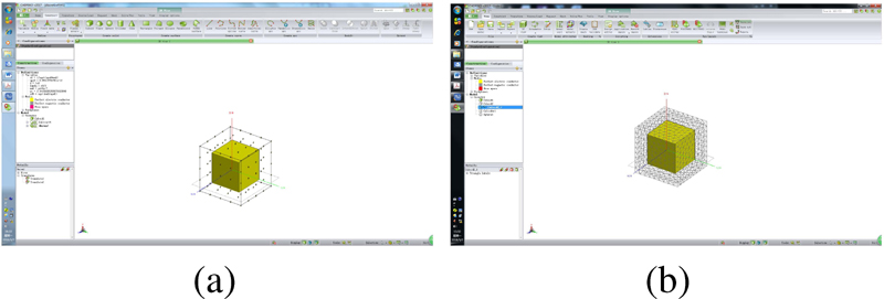
Figure 3: A cube is surrounded by a series of auxiliary exciting sources: (a) auxiliary exciting sources are defined on a series of discrete small RWG functions and (b) auxiliary exciting sources are defined on a meshed surface (shown in the wire-frame model).
Initially, Matekovits et al. define auxiliary exciting sources on a series of discrete small RWG functions around the target, as shown in Fig. 3 (a). After that, Bo Zhang et al. define auxiliary exciting sources on a meshed surface [17], as shown in Fig. 3 (b). Since the surface is meshed into triangular patches in an irregular way, auxiliary exciting source defined on them will be with diverse polarizations which is helpful for improving accuracy. In the following work, the second method of setting auxiliary exciting sources will be adopted.
Step 2: solving the responses of targets to exciting sources to get a solution space (both natural exciting source and auxiliary exciting source are included).
If we define the mutual coupling impedance matrix between the target and auxiliary exciting sources as V, the solution space R of synthetic functions can be computed as:
| (9) |
where N is the number of RWG functions defined on the target, and Q is the number of RWG functions defined on auxiliary exciting sources.
Notably, (9) indicates that the solution space contains two parts:
1) response to natural excitations (incident wave)
| (10) |
2) responses to auxiliary exciting sources
| (11) |
where r (i=1,2,…,Q+1) represent the i-th column of solution space R.
Step 3: extracting independent items from solution space.
To extract independent items (expansion coefficients of synthetic functions) from the solution space R, singular value decomposition (SVD) is usually adopted:
| (12) |
where is the -th singular value of and
U is a unitary matrix, and if / (truncation error), we will take the first M columns of U as the expansion coefficients [P] of synthetic functions. Thus, it will be:
| (13) |
where I is the identity matrix.
The truncation error is usually determined by the operator and, in different applications, is also usually different.
Having got the expansion coefficients [P] of synthetic functions, we can compute the current coefficients [Y] of synthetic functions according to (7):
| (14) |
Then, according to (8), we can obtain the current coefficients of RWG functions defined on the surface of targets:
| (15) |
Finally, based on the current coefficients of RWG functions, it is not difficult to calculate other EM properties of the target. As it is similar to the traditional MoM, we are not going to explain it in detail.
B. ESS Modeling
In SFX, triangular meshes and RWG functions are usually adopted. For the ESS array shown in Fig. 1, each element is divided into 164 triangular meshes and 188 RWG functions are defined on these meshes, as shown in Fig. 4. Thus, there are 188*210=39480 unknowns in total for the whole ESS array. In traditional MoM, the impedance matrix is a N*N (the number of unknowns) dense matrix of complex coefficients which means the memory cost impedance matrix will be 39480*39480*2*4 Byte/float11.6 GByte. To decrease the number of unknowns, synthetic functions are used to compress the scale of the matrix equation.
To construct synthetic functions, a virtual meshed surface is created around each element and 288 RWG functions are defined on these meshes working as the auxiliary sources, as shown in Fig. 4.
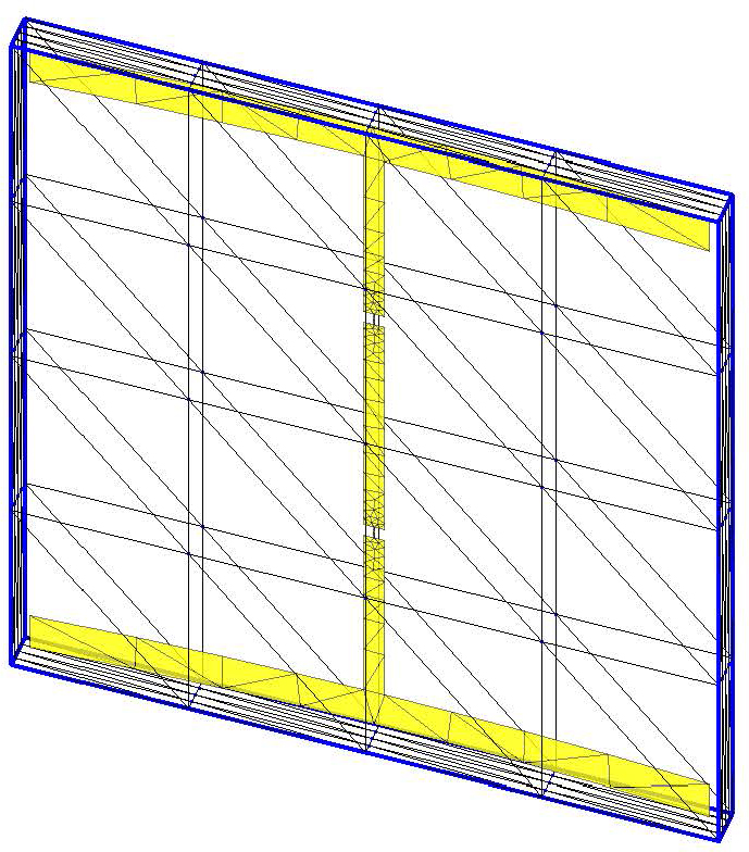
Figure 4: Each element is divided into 164 triangular meshes and a virtual meshed surface is created around the element.
Fortunately, for the ESS array, synthetic functions defined on different elements can be reused based on the geometric similarities between these elements [10]. This feature is rather appealing to us, especially in the analysis of quasi-periodic structures. It means the construction of synthetic functions only needs to be carried out once, which is helpful to improve efficiency for large-scale arrays. In this paper, after optimization, only 5 synthetic functions for each element are enough to get a satisfying accuracy. Thus, for the whole ESS array, the number of unknowns will be only 210*5=1050 for SFX. So, the scale of the matrix equation in (7) is 1050*1050, which is much smaller than that of traditional MoM.
For the analysis of ESS, another emphasis is on the modeling of diodes. In this paper, a thin strip is used to approximate the feeder line and the diodes are viewed as a complex impedance in the middle of the feeder line, as shown in Fig. 5. Technically, arbitrary two-port equivalent circuit models could be handled in this method.
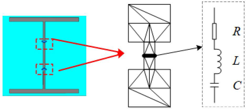
Figure 5: A thin strip is used to approximate the feeder line and the diodes can be viewed as a complex impedance in the middle of the feeder line.
To take the diodes into consideration, we need to modify the diagonal elements of the impedance matrix, as shown in (16):
| (16) |
where ,, which are consistent with the simulation setup in the Section II.
Compared to the simulating model in Feko, the model used in this paper can transform the connection from a wire-surface problem to a surface-surface problem and can be perfectly addressed by RWG functions, shown in Fig. 6.
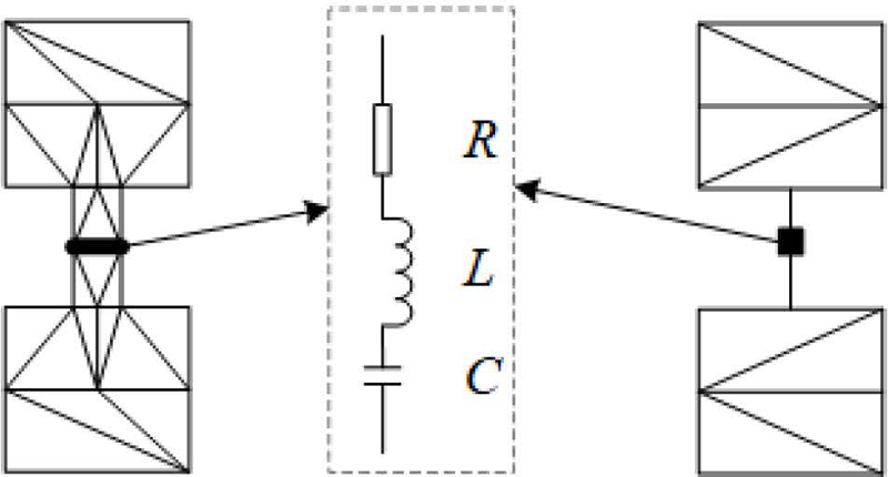
Figure 6: The diode simulating model in Feko (right) and in this paper (left).
IV. RESULTS
To illustrate the accuracy and efficiency of SFX, the EM properties of the ESS array are numerically analyzed with different methods based on commercial software for comparison. Specifically, the following numerical methods are adopted: MOM and multi-layer fast multipole method (MLFMM) with Feko (Altair Feko 2020), FIT with CST (CST Studio Suite 2021). Considering that the boundary conditions play a critical role in the accuracy in time domain calculations, the boundary conditions in CST are set as open boundary conditions (perfectly matched layers, PML) with a minimum distance to structures of , and the estimated refection level is 0.0001. The outer excitation is a plane wave which comes from +x axis and polarizes +z axis with its frequency being 10 GHz. Both the far-field (Bistatic RCS) and near field (electric field at z=0 mm cut-plane) are calculated. All the simulations are carried on a computer poses 8 Intel Core i7-7700K Processors with 4 cores per CPU running at 4.2 GHz.
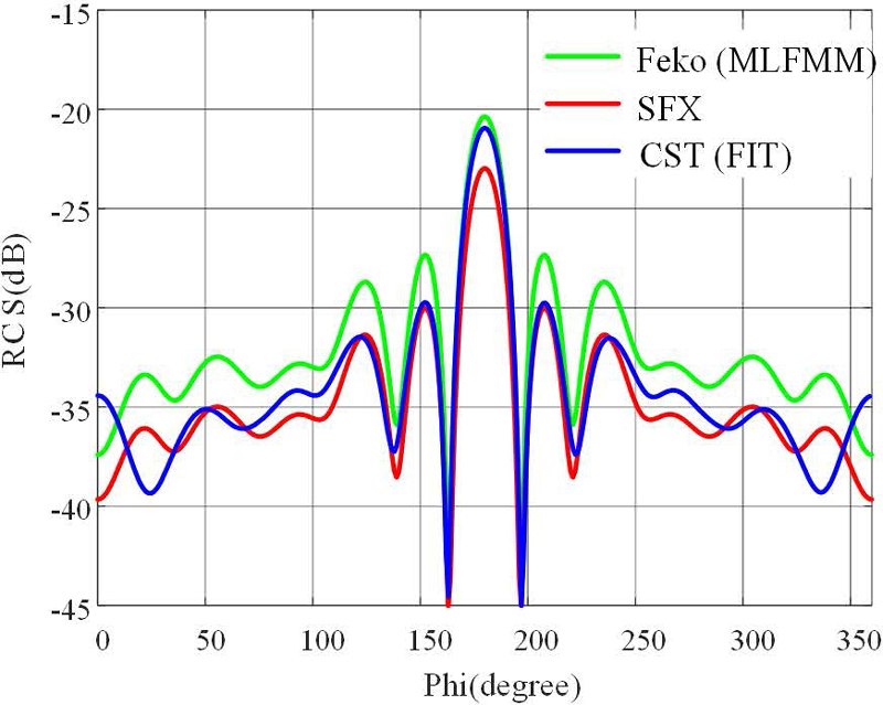
Figure 7: The RCS of the cylindrical conformal ESS array calculated by different methods when diodes are in OFF state.
The results of the Bistatic RCS of the ESS array obtained by different methods are shown in Figs. 7 and 8 with diodes in different states, respectively. When the diodes are in OFF state, the transmission coefficient of ESS is high and almost transparent to the incident waves. Therefore, the RCS is supposed to be low and the results are smaller than -20 dB (Fig. 7). On the contrary, the RCS is much larger because the incident wave is strongly reflected when the diodes are in ON state (Fig. 8). Notably, in Fig. 7, when the diodes are OFF, the RCS of ESS array obtained by different methods shows a similar trend with an error smaller than 2.6 dB. On the main lobe, the largest RCS value comes from Feko (MLFMM) (-20.4 dB) and then follows CST (FIT) (-20.9 dB) and SFX (-23.0 dB). Because the absolute value of RCS is very low, the real error between different methods is actually small. As the RCS becomes much larger in Fig. 8, the results obtained with different values are in good agreement, which confirms the accuracy of SFX. It should be pointed out that the results of Feko (MoM) and Feko (MLFMM) are the same, therefore, only Feko (MLFMM) is presented.
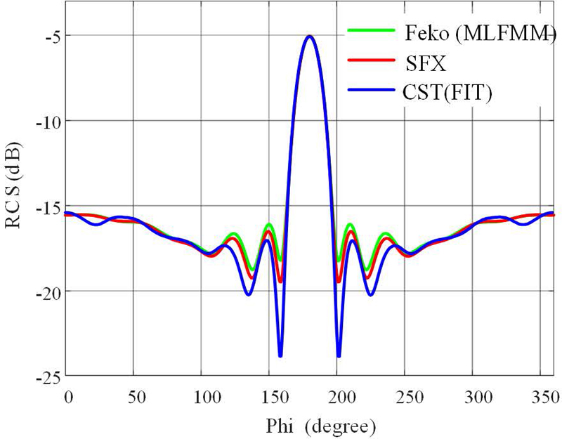
Figure 8: The RCS of the cylindrical conformal ESS array calculated by different methods when diodes are in ON state.
The distribution of electric field obtained with different methods at the cut-plane z=30 mm are demonstrated in Figs. 9, 10, and 11. As we can see, the electric field is more uniform when the diodes are OFF, which means the ESS array generates a minor influence on the incident waves. However, when the diodes are ON, the incident wave is reflected rather than propagate through the ESS array from the left to the right. As a result, the electric field at the right side of ESS array is much smaller than that at the left side. That is to say, the incident wave will be isolated out of the ESS array.
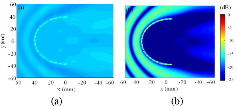
Figure 9: The electric field distribution of the cylindrical conformal ESS array calculated with SFX when the diodes are in different states (a) OFF and (b) ON.
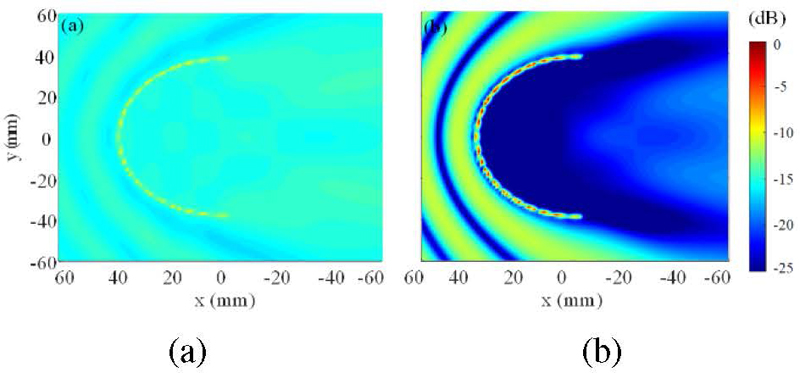
Figure 10: The electric field distribution of the cylindrical conformal ESS array calculated with Feko (MLFMM) when the diodes are in different states (a) OFF and (b) ON.
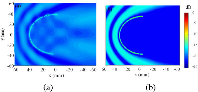
Figure 11: The electric field distribution of the cylindrical conformal ESS array calculated with CST (FIT) when the diodes are in different states (a) OFF and (b) ON.
Furthermore, the IL and SE of the ESS array are calculated with different methods, as given in Table 1. Results obtained with the periodic boundary conditions are also provided here for comparison. Obviously, the results show a significant difference between IL and SE, confirming the capability of ESS for high-power EM wave protection. As we can see, the IL obtained from the finite ESS array is larger but the SE is smaller than that of the unit cell, where ESS is regarded as infinite arrays. The results can be attributed to several reasons. Firstly, the array is not a strictly enclosed one, which may lead to some EM leaks. Secondly, the IL and SE are obtained based on the field intensity in the near field area of the ESS array while that of the unit cell are calculated with field intensity in the far field area, which also leads to some error. Generally, the results obtained by different methods are in agreement.
Table 1: The IL and SE of ESS obtained with different methods
| IL (dB) | SE (dB) | |
|---|---|---|
| SFX | -0.45 | -16.5 |
| CST (FIT) | -1.26 | -18.4 |
| Feko (MoM) | -0.3 | -17.7 |
| Feko (MLFMM) | -0.3 | -17.7 |
| Unit cell | -0.1 | -20 |
Table 2 illustrates the computational performance of different methods in terms of time consumption, peak memory cost, and root mean square error (RMSE). Notably, the peak memory cost and time consumption of Feko and CST are obtained from the software logfile. It is not difficult to see that the proposed SFX exhibits outstanding performance in accuracy, efficiency, and memory cost. More concretely:
1) According to the RMSE in Table 2, SFX has the same level of accuracy with CST (FIT) and Feko (MLFMM).
2) As for the computational efficiency, according to the indexes of time consumption, SFX is slightly lower than CST (FIT) and Feko (MLFMM), but exceeds traditional Feko (MoM).
3) When it comes to memory cost, SFX shows a huge advantage over other methods, especially CST (FIT) and Feko (MoM).
It is not difficult to draw the conclusion that SFX is especially suitable for the analysis of ESS. Compared to traditional full-wave numerical methods, SFX well overcomes the difficulty of balancing accuracy, efficiency, and resource consumption.
Table 2: Performance and comparison of different algorithms (RMSE is obtained in comparison with the results of Feko)
| Elapsed Time | Peak Memory Cost | RMSE | |
|---|---|---|---|
| SFX | 387.56 s | 8.41 MByte | 0.13 |
| CST (FIT) | 266 s | 1.11 GByte | 0.47 |
| Feko (MoM) | 2350.95 s | 6.55 GByte | - |
| Feko (MLFMM) | 262.16 s | 618.25 Mbyte | - |
V. CONCLUSIONS
ESS is a potential method of high-power EM protection. In this paper, SFX is adopted to numerically analyze the EM properties of ESS and an I-shape cylindrical conformal ESS array is designed for demonstration. Compared to traditional full-wave numerical methods, SFX exhibits great advantages in memory cost while maintaining the same level of accuracy and efficiency with MLFMM and FIT. Moreover, this method not only suits ESS, but also suits other quasi-periodic arrays whose elements share similar geometries. Especially for large-scale array, this method can well overcome the difficulty of balancing accuracy, efficiency, and resourceconsumption.
REFERENCES
[1] P. Liu, C. Liu, J. Tan, Y. Dong, and B. Yi, “Analysis of the research development on HPM/EMP protection,” Chinese Journal of Ship Research, vol. 10, no. 2, pp. 2-6, 2015 [in Chinese].
[2] C. Yang, P. Liu, and X. Huang, “A novel method of energy selective surface for adaptive HPM/EMP protection,” IEEE Antennas Wireless Propag. Lett., vol. 12, pp. 112-115, 2013.
[3] N. Hu, Y. Zhao, J. Zhang, P. Liu, H. Xu, and F. Costa, ”High-performance energy selective surface based on equivalent circuit design approach,” IEEE Trans. Antennas Propag., vol. 70, no. 6, pp. 4526-4538, 2022.
[4] N. Hu, K. Wang, J. H. Zhang, S. Zha, Z. F. Wu, C. Liu, and P. Liu, “Design of ultrawideband energy-selective surface for high-power microwave protection,” IEEE Antennas Wireless Propag. Lett., vol. 18, no. 4, pp. 669-673, 2019.
[5] N. Hu, S. Zha, T. Tian, and P. Liu, “Design and analysis of multiband energy selective surface based on semiconductors,” IEEE Trans. Electromagn. Compat., vol. 64, no. 4, pp. 1076-1085, 2022.
[6] Z. Wu, Y. Xu, P. Liu, T. Tian, and M Lin, “An ultra-broadband energy selective surface design method: From filter circuits to metamaterials,” IEEE Trans. Antennas Propag., vol. 71, no. 7, pp. 5865-5873, 2023.
[7] W. Kui, X. Huang, T. Tian, W. Huang, and P. Liu, -1447283793-1447283793“Design and demonstration of high-power density infrared nonlinear filtering window with EM shielding,” Opt. Express., vol. 32, pp. 5956-5968, 2024.
[8] T. Tian, X. Huang, Y. Xu, P. Liu, C. Liu, N. Hu, J. Zhang, and Z. Wu, “A wideband energy selective surface with quasi-elliptic bandpass response and high-power microwave shielding,” IEEE Trans. Electromagn. Compat., vol. 61, no. 1, pp. 224-233, 2024.
[9] L. Tarricone, “A genetic approach for the efficient numerical analysis of microwave circuits,” Applied Computational Electromagnetics Society (ACES) Journal, vol. 1, no. 1, pp. 87-93, 2000.
[10] Z. Jiang, Y. Sha, X. Xuan, and L. Nie, “An omnidirectional antenna with multi-taper conformal structure,” Applied Computational Electromagnetics Society (ACES) Journal, vol. 38, no. 3, pp. 184-192, 2023.
[11] G. Sener, “Antenna synthesis by Levin’s method using a novel optimization algorithm for knot placement,” Applied Computational Electromagnetics Society (ACES) Journal, vol. 38, no. 7, pp. 482-488, 2023.
[12] Y. Xu, X. Huang, C. Liu, S. Zha, and J. Liu, “Synthetic functions expansion: Automation, reuse, and parallel,” IEEE Trans. Antennas Propag., vol. 69, no. 3, pp. 1825-1830, 2021.
[13] L. Matekovits, G. Vecchi, G. Dassano, and M. Orefice, “Synthetic function analysis of large printed structures: The solution space sampling approach,” Proc. IEEE AP-S Int. Symp., Boston, MA, pp. 568-571, 2001.
[14] L. Matekovits, V. A. Laza, and G. Vecchi, “Analysis of large complex structures with the synthetic-functions approach,” IEEE Trans. Antennas Propag., vol. 55, no. 3, pp. 2509-2521, 2007.
[15] W. C. Chen, G. B. Xiao, S. Xiang, and J. F. Mao. “A note on the construction of synthetic basis functions for antenna arrays,” IEEE Trans. Antennas Propag., vol. 60, no. 7, pp. 3509-3512, 2012.
[16] Y. L. Xu, H. Yang, W. K. Yu, and J. Zhu. “An automatic scheme for synthetic basis functions method,” IEEE Trans. Antennas Propag., vol. 66, no. 3, pp. 1601-1606, 2018.
[17] B. Zhang, G. B. Xiao, J. Mao, and Y. Wang, “Analyzing large-scale non-periodic arrays with synthetic basis functions,” IEEE Trans. Antennas Propag., vol. 58, no. 11, pp. 3576-3584, 2010.
[18] L. Matekovits, G. Vecchi, M. Bercigli, and M. Bandinelli, “Synthetic-functions analysis of large aperture-coupled antennas,” IEEE Trans. Antennas Propag., vol. 57, no. 7, pp. 1936-1943, 2009.
[19] Y. L. Xu, H. Yang, D. Peng, and R. J. Shen, “Efficient numerical analysis of dielectric resonator antenna arrays,” IEEE Antennas Wireless Propag. Lett., vol. 27, no. 4, pp. 670-674, 2018.
BIOGRAPHIES

Ning Hu received the B.S. degree in electronic engineering and the M.S. degree in electronic science and technology from National University of Defense Technology (NUDT), Changsha, Hunan, P. R. China, in 2017 and 2019, respectively. And he received the Ph.D. degree in information and communication engineering from NUDT in 2023. His research interests include electromagnetic compatibility and protection, metamaterials and antennas.

Yanlin Xu was born in Tianchang, Anhui, China, in 1990. He received the B.S. and M.S. degrees in electronic science and technology from National University of Defense Technology (NUDT), Chang-sha, China, in 2013 and 2015, respectively. He received the Ph.D. degree in information and communication engineering from NUDT in 2018. His current research interests include electromagnetic compatibility and protection, computational electromagnetics and its applications in scattering analysis.

Peiguo Liu received the Ph.D. degree in information engineering from the National University of Defense Technology, Changsha, China, in 1995. He is currently a Professor with the College of Electrical Science and Engineering, National University of Defense Technology. His current research interests include electromagnetic compatibility and protection.
ACES JOURNAL, Vol. 39, No. 2, 115–122
doi: 10.13052/2024.ACES.J.390204
© 2024 River Publishers