A New Miniaturized Double Stop-band Frequency Selective Surface
Qiannan Li1,2, Qing Wang2, Hui Zhang1, Jian-Qiang Hou2, and Jun Zhao2
1College of Physics and Electronic Engineering
Xianyang Normal University, Xianyang, 712000, China
2321887532@qq.com, xdzhxy@163.com
2School of Physics and Electrical Engineering
Xidian University, Xi’an, 710071, China
wangqing@mail.xidian.edu.cn
Submitted On: July 13, 2023; Accepted On: February 7, 2024
ABSTRACT
A miniaturized double stop-band FSS for WLAN was proposed based on the structure of a ring patch with internal branches and a cross zigzag loaded line. This construction is obtained by using the multilayer connection method to paint the two layers of the patch that we designed on the top and bottom of the dielectric substrate to simulate the designed construction by using HFSS simulation. Analyzing the frequency response characteristics of the FSS indicates that the construction can generate two transmission band gaps at 1.92-2.17 GHz and 4.94-5.99 GHz in the WLAN wave. This construction has stronger polarization stability and angle stability when the incident electromagnetic wave is 0-60. It also has a simple construction, small size, and significant engineering applicationvalue.
Index Terms: Double stop-band, frequency selective surface (FSS), miniaturization, wireless local area network (WLAN).
I. INTRODUCTION
The typical frequency selective surface (FSS) is either a single layer or multilayer formed by coating a certain shape of metal patch (bandstop) or metal aperture (bandpass) on a dielectric substrate in a two-dimensional periodic array structure [1–5], which is essentially a spatial filter that has frequency selection characteristics for electromagnetic waves with different operating frequencies, polarization states, and incident angles, and does not absorb radio frequency energy [6]. The frequency response of FSS is mainly affected by the shape, size, and arrangement of the unit structure, the dielectric constant, and the thickness of the dielectric substrate. Its filtering characteristics can be controlled by adjusting its structural parameters. According to its filtering performance, FSS is mainly divided into four types: low pass, high pass, bandpass, and bandstop. It has been widely used in communications [7, 8], electromagnetic shielding [9–11], and radar stealth fields [12–14]
A series of studies on frequency selective surfaces originated from Francis Hopkinson [15] in 1785, who observed the diffraction spot phenomenon. Subsequently, American scientists Hopkinson and Rittenhouse [16] found through experiments that white light is decomposed into monochrome light when passed through thin ribbons. Since then, a series of studies on frequency selective surfaces have been developed. In the 19th century, Fraunhofer and Hertz further explained the phenomenon through experiments. In the 1970s, Munk [17] and Luebbrs completed basic theoretical research on typical FSSs. In recent years, with the improvement of channel capacity and communication quality, single frequency FSSs can no longer meet the requirements of high communication capacity, and the multifrequency design of FSSs has become a popular topic of research. At present, the design of a multiband FSS can be realized by multilayer cascade [18, 19], the multiple resonant element method [20], composite technology [21, 22], fractal structure [23, 24], and other methods. Much work has been performed on the design of multiband FSSs. In 2015, Majidzadeh [25] and others devised a combined FSS, based on the angle of the fractal and combined units, which can realize multiband filtering. In 2016, Gao [26] and others, based on the multi-resonance unit method, proposed a double-pass band FSS with a square grid and hybrid resonant structure. In the same year, Palange [27] and others designed a triple bandstop FSS with a fractal structure. In 2017, Zhou Yulong and others designed a windmill-type double stop-band FSS through electric dipole resonance and windmill FSS high-order mode resonance, which can realize -35 dB electromagnetic shielding in the band. In 2018, based on the multilayer cascade method, Malone and others applied a quadrilateral ring dual bandpass FSS for the X-band and K-band. In 2019, based on the square ring structure, Zhou Ruicheng and others designed a three-way band FSS by using the multilayer cascade method, with a pass-band reflection coefficient of -30 dB.
There are few reports on the miniaturized band-stop FSS design of the wireless local area network (WLAN) frequency band. Based on previous studies, this paper proposes a new miniaturized dual stop-band frequency selective surface for WLAN. The structure is formed by coating different shapes of metal patches on the upper and lower sides of the dielectric substrate. This proposed structure achieves a strong shielding effect on electromagnetic waves in the WLAN frequency band and has strong polarization, angular stability, a simple structure, and easy processing.
II. STRUCTURE DESIGN
The resonant frequency of any FSS mainly depends on the size of the unit. For a specific structure, when the size and wavelength have a definite relationship, total reflection or total transmission of electromagnetic waves will occur on the FSS structure. Based on this, a dual-band blocking FSS applied to WLAN is proposed. As shown in Fig. 1 (a), this structure is divided into two layers: the ring patch [28] and the zigzag line structure based on the shape of a cross. These shapes are coated separately and are on the upper and lower sides of a square dielectric substrate with a side length P and thickness h respectively. The upper and lower structures of the designed FSS are shown in Figs. 1 (b) and (c). The double-band miniaturization design of the FSS is realized by loading branches inside the upper ring and twisting the lower cross-shaped structure. The dielectric substrate is tp-2, the dielectric constant is 6.55, and the loss tangent is 0.001. Table 1 shows the structural parameters of the FSS unit.
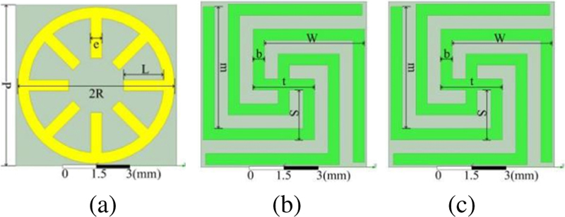
Figure 1: Evolution of our FSS design: (a) ring patch structure loaded with internal branches, (b) zigzag line structure based on cross, and (c) evolved final shape of our FSS.
Table 1: FSS unit structure parameters
| Parameter | P | R | L | e | T |
| Value(mm) | 7.3 | 3.06 | 1.82 | 0.5 | 2.7 |
| Parameter | S | W | M | b | H |
| Value (mm) | 2.2 | 4.4 | 5.39 | 0.5 | 1.5 |
III. SIMULATION ANALYSIS AND OPTIMIZATION
A. FSS design process analysis
The electromagnetic simulation software HFSS is used for simulation calculation. Periodic boundary conditions are set along the x-axis and y-axis, and the Floquet excitation port is set on the z-axis to make the plane electromagnetic wave incident perpendicular to the FSS surface along the z-axis.
Figure 2 shows the frequency response characteristic curve of the single layer ring loaded branch structure. Figures 2 (a) and (b) show the influence that the curves of the ring outer radius R and the branch length L have on the FSS frequency response S, respectively. When the value of R is increased from 3 mm to 3.2 mm, and L is increased from 1.5 mm to 1.9 mm, the resonance points of the single-layer ring-loaded branch structure FSS all move in the low-frequency direction, and the stop-band bandwidth becomes slightly wider. When R is 3 mm and L is 1.5 mm, the stop-band range of the FSS is 3.37-6.99 GHz, and the in-band resonance point is 5.51 GHz, which can shield the electromagnetic wave in the 5 GHz (5.030-5.835 GHz) frequency band of the WLANby -68 dB.
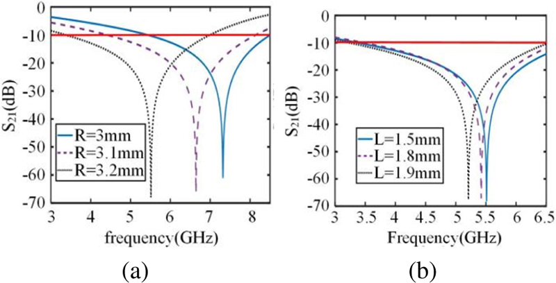
Figure 2: Frequency response characteristic curve 3 of the ring-loaded branch structure: (a) the influence of the ring outer radius R on the FSS frequency response and (b) the influence of the stub length L on the FSS frequency response.
Figure 3 shows the influence curve of the outermost line of the single-layer cross meander line structure (m) on the frequency response of the FSS. In the process of increasing m from 3.8 mm to 5.4 mm, the resonance point of the cross meander line structure FSS moves in the low-frequency direction from 2.81 GHz to 2.38 GHz, and the stop-band bandwidth is basically unchanged. When m is 4.8 mm, the FSS stop-band range of the structure is 1.94-2.87 GHz, and the resonance point is 2.46 GHz, which can shield the electromagnetic wave in the 2.4 GHz (2.4-2.4835 GHz) frequency band of the WLAN with -62 dB.
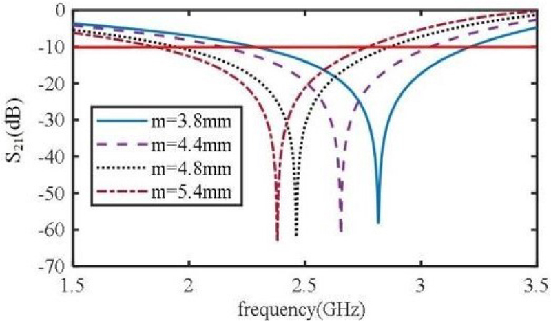
Figure 3: The influence of the outer line length m of the cross zigzag line structure on the frequency response of FSS.
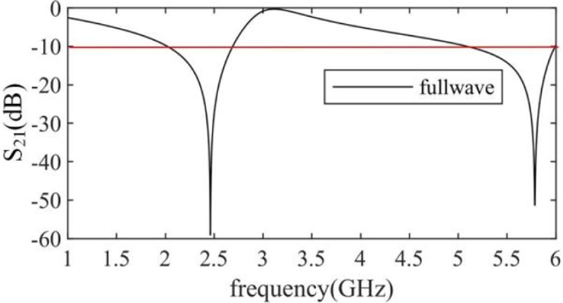
Figure 4: Frequency response characteristic curve of the dual-frequency FSS.
The research shows that the multiband design of FSSs can be realized through the multilayer cascade method. Based on this, this research cascades the ring-loaded branch structure and the cross zigzag structure in Section A and uses the parameter optimization function of HFSS to complete it. The frequency response characteristic curve of the new double-layer FSS after the wave simulation optimization design is shown in Fig. 4, and the optimized structural parameters are shown in Table 1. These show that the new FSS exhibits dual stop-band characteristics. Two transmission bands are formed at 1.92-2.71 GHz and 4.94-5.99 GHz. The resonance frequencies are f=2.45 GHz and f=5.80 GHz. The working frequency ranges of WLAN are 2.4-2.4835 GHz and 5.030-5.835 GHz. The designed FSS stop-band rejection is -60 dB and -45 dB, respectively. This structure has an excellent ability to suppress electromagnetic waves in the WLAN frequency band. The size of the designed FSS unit is 7.3 mm7.3 mm. It is known that the resonance frequency in the 2.4 GHz frequency range is f=2.45 GHz, c=310 m/s, and the wavelength of the first resonance frequency in vacuum is =122.45 mm. Through analysis, it can be seen that the size of the designed FSS unit is 0.05960.0596, which meets the miniaturization design requirements and can be used in actual projects.
B. Analysis of the surface current distribution
When the electromagnetic wave is incident on the FSS, the surface of the FSS will excite the surface current, and the scattered field that is generated will affect the transmittance of the electromagnetic wave. The filtering mechanism of the designed structure in the WLAN frequency range can be investigated by analyzing the surface current distribution of the FSS at the transmission zero point. By using the J-Surf function in HFSS to view the surface current distribution of the designed FSS, Figs. 5 (a) and (b) show the surface current distribution of the designed FSS when electromagnetic waves are perpendicular to 2.45 GHz and 5.9 GHz, respectively. Figure 5 (a) shows that the current when electromagnetic waves are incident at 2.45 GHz is mainly distributed in the lower structure of the FSS, which indicates that f is mainly generated by the lower cross zigzag line structure. Figure 5 (b) shows that the current is mainly distributed in the upper structure when electromagnetic waves are incident at 5.6 GHz perpendicularly. It shows that f is mainly produced by the upper ring-loaded branch structure. Obviously, the FSS filter characteristics can be controlled by adjusting the structural parameters of the upper and lower units.
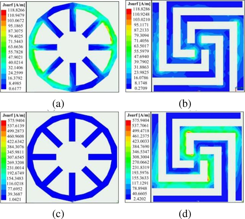
Figure 5: FSS surface current distribution: (a) on the upper surface of the FSS when the frequency is 2.4 GHz, (b) on the lower surface of the FSS when the frequency is 2.4 GHz, (c) on the upper surface of the FSS when the frequency is 5.6 GHz, and (d) on the lower surface of the FSS when the frequency is 5.6 GHz.
C. Analysis of the relationship between the structure size and frequency response characteristics
Figures 6–8 show the influence curves of m, L, and R on the frequency response characteristics of the designed FSS. With increasing m, the transmission zero frequency of the 2.45 GHz band of the dual-frequency FSS shifts to the left, and the bandwidth is basically unchanged. The transmission zero frequency of the 5 GHz band is maintained at 5.8 GHz. With increasing L and R, the 5 GHz transmission zero frequency of the dual-band FSS shifts to the left, and the stop-band bandwidth increases slightly. The transmission zero point of the 2.4 GHz frequency band is basically unchanged. The frequency response in the 2.4 GHz frequency band is only affected by m, while L and R mainly regulate the frequency response in the 5 GHz frequency band.
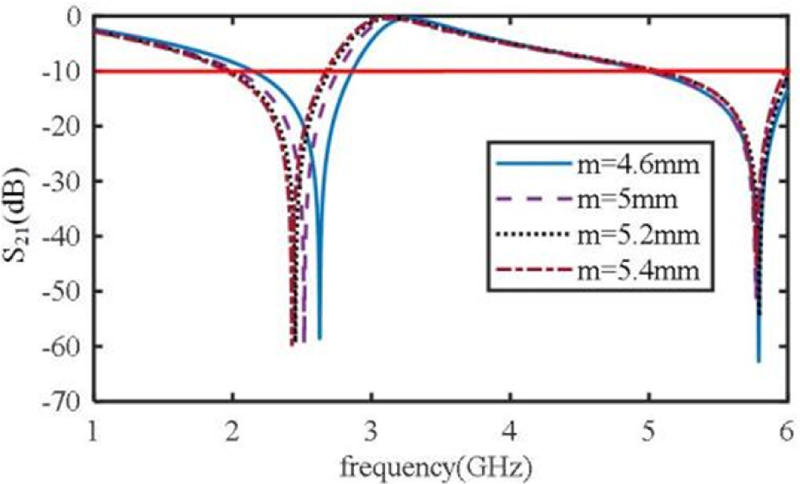
Figure 6: The influence of m on the frequency response of the dual-band FSS.
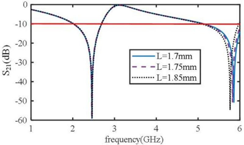
Figure 7: The influence of L on the frequency response of the dual-band FSS.
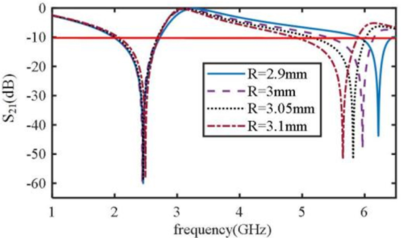
Figure 8: The influence of R on the frequency response of the dual-band FSS.
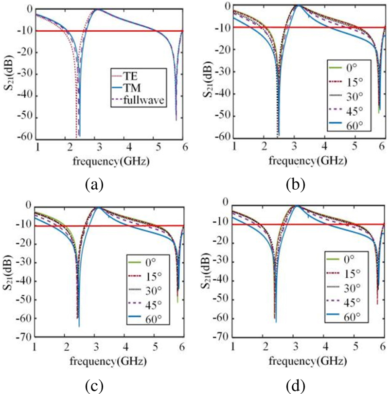
Figure 9: Frequency response characteristic curve of the FSS when different polarized waves are incident at different angles: (a) polarization characteristics of the dual-band FSS, (b) S curve of FSS when the electromagnetic wave is incident at different angles in full wave mode, (c) S curve of FSS when the electromagnetic wave is incident at different angles in transverse electric (TE) polarizations wave mode, and (d) S curve of the FSS when the electromagnetic wave is incident at different angles in the transverse magnetic (TM) polarizations wave mode.
In engineering applications, most of the time, electromagnetic waves are incident to an FSS at a certain angle, and the polarization modes of incident waves are diverse. To study the influence of the incident angle and polarization mode of the incident wave on the FSS designed in this paper, the FSS is irradiated with 0, 15, 30, 45, and 60 plane electromagnetic waves. The relationship between its frequency response curve and incident angle is obtained through an HFSS simulation calculation. Figure 9 (a) shows the S curve of the FSS under transverse electric (TE) polarizations, transverse magnetic (TM) polarizations, and full wave simulation. Figures 9 (b), (c), and (d) show the S curve of the full wave mode, transverse electric (TE) polarizations wave mode, and transverse magnetic (TM) polarizations wave mode when the electromagnetic wave is incident on the FSS at 0-60. We find that the polarization mode of the incident wave does not affect the frequency response of the FSS in the 5 GHz frequency band. The transmission zero point within the 2.4 GHz frequency band is offset to the low frequency by 0.06 GHz when the transverse electric (TE) polarizations wave is incident. When the transverse magnetic (TM) polarizations wave is incident, it is offset to high frequency by 0.04 GHz, and the offset is small. Under different incident wave modes, when the incident angle of the designed FSS increases from 0-60, the bandwidth of the two transmission stop-bands in the WLAN frequency band increases, the transmission zero point is basically maintained at approximately 2.45 GHz and 5.8 GHz, and the offset is very small. It shows that when different polarization waves are incident on the FSS at different angles, the FSS can show a better double stop-band function, and the structure has strong polarization stability and anglestability.
IV. EXPERIMENTAL VERIFICATION
To better verify the performance of the proposed FSS, a 190190 mm FSS model was machined on tp-2 substrate with a thickness of 1.5 mm using printed circuit board technology, which is composed of 2626 small unit structures, as shown in Fig. 10. The material of the medium substrate is tp-2 and its relative dielectric constant is 6.55 with the loss tangentof 0.001.
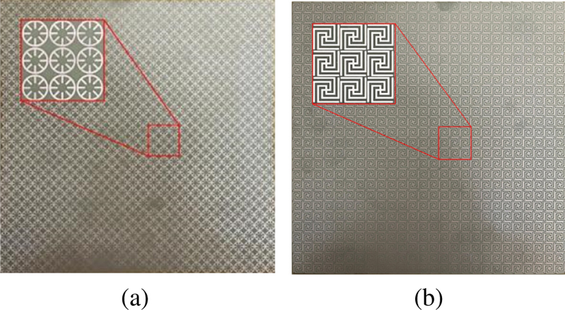
Figure 10: Photographs of the fabricated prototypes: (a) upper surface and (b) lower surface.
The frequency responses of the proposed FSS are measured by the free-space method [29], and its measurement environment is given in Fig. 11. There are two horn antennas (operating from 2 to 8 GHz), the FSS prototype, and turntable (can be used to adjust the angle of the incident wave). The FSS prototype is placed on the turntable for measurement of incident stability. A pair of horn antennas are located about 0.35 m apart from each side of the centered rotatable screen, so that a uniform plane wave striking upon the FSS. The two horn antennas are connected by the vector networkanalyzer.
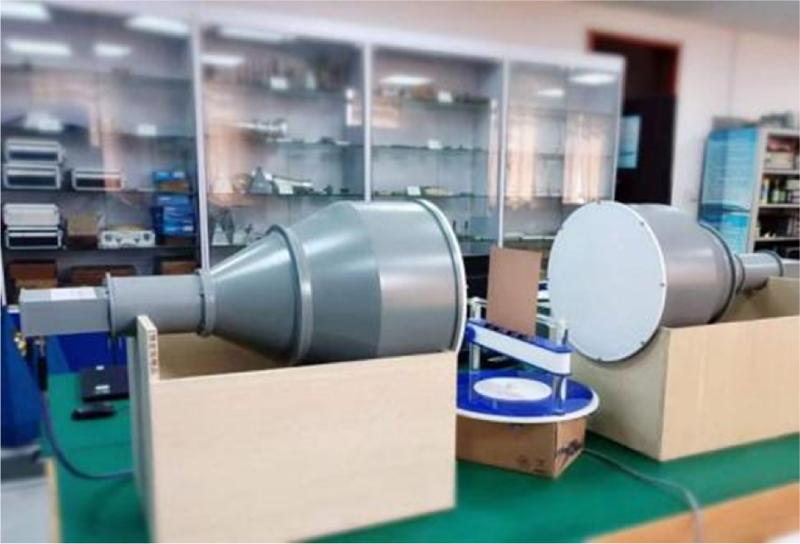
Figure 11: Measurement setup.
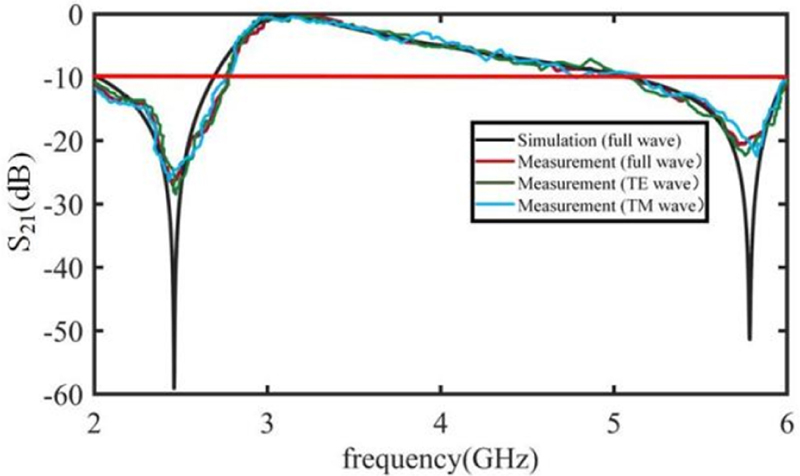
Figure 12: Frequency response characteristic curve comparison between full-wave simulation and the transverse electric (TE) and transverse magnetic (TM) polarizations measurement data.
The measured results under different polarizations are demonstrated in Fig. 12 compared with the simulated ones. The measurement results under different incident angles are shown in Fig. 13. It is clear that the transmission coefficients keep very stable for transverse electric (TE) and transverse magnetic (TM) polarizations. It is clear from the Fig. 13 that the proposed double layer FSS provides closely spaced dual stop-band response with highly stable angular independency. The frequency response characteristic curve of the FSS tested very closely resembles the simulation results. The operating frequency bands are 2-2.8 GHz and4.9-6 GHz.
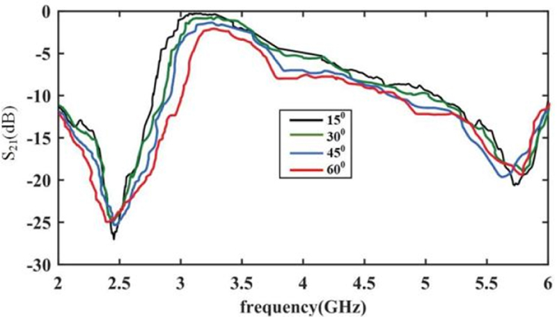
Figure 13: Measurement results at different incident angles conditions.
V. CONCLUSION
Based on the traditional cross and ring structures, this paper proposes a miniaturized dual stop-band FSS applied to WLAN using the multilayer cascade method. In this structure, the designed two layers of patches are coated on the upper and lower layers of the dielectric substrate, and independent control of the transmission zero point can be realized by adjusting the geometric parameters of the upper and lower patch units. This structure produces two transmission band gaps in the WLAN frequency band, and the structure has better polarization stability and angle stability in the working frequency band. Both the simulation results and the measured results show that the FSS has good performance and can be applied to practical projects.
ACKNOWLEDGMENT
This study was partially supported by Provincial Science Foundation of Shaanxi (2021JM-128).
REFERENCES
[1] Y. Li, P. Ren, Z. Xiang, and B Xu, “Design of dual-stopband FSS with tightly spaced frequency response characteristics,” IEEE Microwave and Wireless Components Letters, vol. 32, no. 8, pp. 1011-1014, Apr. 2022.
[2] X.-J. Sheng, J.-J. Fan, N. Liu, and C.-B. Zhang, “A miniaturized dual-band FSS with controllable frequency resonances,” IEEE Microw. Wireless Compon. Lett, vol. 27, no. 10, pp. 915-917, Oct. 2017.
[3] S. Dey, “Conformal miniaturized angular stable triband frequency selective surface for EMI shielding,” IEEE Transactions on Electromagnetic Compatibility, vol. 64, no. 4, pp. 1031-1041, Mar. 2022.
[4] X. Zhou, B. Yuan, S. Chen, and G. Wang, “A novel design of a compact frequency-selective surface with high selectivity and angular stability,” IEEE Microwave and Wireless Components Letters, vol. 32, no. 7, pp. 931-934, Mar. 2022.
[5] P. Jiang, W. Jiang, W. Hu, and S. Gong, “An interlaced grid dual-band dual-polarized bandpass FSS with a large band ratio,” IEEE Antennas and Wireless Propagation Letters, vol. 21, no. 5, pp. 1027-1031, Mar. 2022.
[6] L. Zhao, X. Liang, Z.-M. Chen, Y. Lee, S. Zhang, H. Ma, and X. Shen, “An ultraminiaturized dual-stopband frequency selective surface for ultra high frequency,” IEEE Access, vol. 8, pp. 44830-44835, Mar. 2020.
[7] G. D. Catton, H. G. Espinosa, A. A. Dewani, and S. G. O’Keefe, “Miniature convoluted FSS for gain enhancement of a multiband antenna,” IEEE Access, vol. 9, pp. 36898-36907, Feb. 2021.
[8] A. J. A. Al Gburi, I. B. M. Ibrahim, M. Y. Zeain, and Z. Zakaria, “Compact size and high gain of CPW-fed UWB strawberry artistic shaped printed monopole antennas using FSS single layer reflector,” IEEE Access, vol. 8, pp. 92697-92707, May 2020.
[9] N. Liu, X. Sheng, C. Zhang, and D. Guo, “Design of frequency selective surface structure with high angular stability for radome application,” IEEE Antennas and Wireless Propagation Letters, vol. 17, no. 1, pp. 138-141, Jan. 2018.
[10] H. Huang and Z. Shen, “Low-RCS reflectarray with phase controllable absorptive frequency-selective reflector,” IEEE Transactions on Antennas and Propagation, vol. 67, no. 1, pp. 190-198, Jan. 2019.
[11] M. Koohestani, R. Perdriau, M. Ramdani, and J. Carlsson, “Frequency selective surfaces for electromagnetic shielding of pocket-sized transceivers,” IEEE Transactions on Electromagnetic Compatibility, vol. 62, no. 6, pp. 2785-2792, Dec. 2020.
[12] S. Narayan, G. Gulati, B. Sangeetha, and R. U. Nair, “Novel metamaterial-element-based FSS for airborne radome applications,” IEEE Trans. Antennas Propag, vol. 66, no. 9, pp. 4695-4707, Sep. 2018.
[13] B. Gao, S. Huang, Z. Ren, Y. Chen, and X. Wang, “Design and verification of an integrated free-standing thick-screen FSS radome,” IEEE Antennas and Wireless Propagation Letters, vol. 17, no. 9, pp. 1630-1634, Sep. 2018.
[14] J. Jiao, N. Xu, and J. Gao, “Complementary frequency selective surface with polarization selective responses,” Applied Computational Electromagnetics Society (ACES) Journal, vol. 37, no. 4, pp. 382-387, Apr. 2022.
[15] R. Mittra, C. H. Chan, and T. Cwik, “Techniques for analyzing frequency selective surfaces-A review,” Proceedings of the IEEE, vol. 76, no. 12, pp. 1593-1615, Dec. 1988.
[16] F. Hopkinson and D. Rittenhouse, “An optical problem, proposed by Mr. Hopkinson, and solved by Mr. Rittenhouse,” Trans. Amer. Phil. Soc, vol. 2, pp. 201-206, 1786.
[17] B. Munk, R. Kouyoumjian, and L. Peters, “Reflection properties of periodic surfaces of loaded dipoles,” IEEE Transactions on Antennas and Propagation, vol. 19, no. 5, pp. 612-617, Sep. 1971.
[18] M. Yan, J. Wang, H. Ma, M. Feng, Y. Pang, S. Qu, J. Zhang, and L. Zheng, “A tri-band, highly selective, bandpass FSS using cascaded multilayer loop arrays,” IEEE Transactions on Antennas and Propagation, vol. 64, no. 5, pp. 2046-2049, May 2016.
[19] S. Vegesna, Y. Zhu, A. Bernussi, and M. Saed, “Terahertz two-layer frequency selective surfaces with improved transmission characteristics,” IEEE Transactions on Terahertz Science and Technology, vol. 2, no. 4, pp. 441-448, July 2012.
[20] M. Gao, S. M. A. Momeni Hasan Abadi, and N. Behdad, “A dual-band, inductively coupled miniaturized-element frequency selective surface with higher order bandpass response,” IEEE Transactions on Antennas and Propagation, vol. 64, no. 8, pp. 3729-3734, Aug. 2016.
[21] W. Wan, Y. Li, H. Wang, Y. Cheng, Z. Zhu, H. Chen, W. Wang, L. Zheng, J. Wang, and S. Qu, “Composite frequency selective structure with the integrated functionality of transmission, absorption, and scattering,” IEEE Antennas and Wireless Propagation Letters, vol. 20, no. 9, pp. 1819-1823, Sep. 2021.
[22] Y. Ma, X. Zhang, S. Wu, Y. Yuan, and N. Yuan, “A hybrid 2-d-3-d miniaturized multiorder wide bandpass FSS,” IEEE Antennas and Wireless Propagation Letters, vol. 21, no. 2, pp. 307-311, Feb.2022.
[23] L. Murugasamy and R. Sivasamy, “A novel fractal inspired iterated four-legged loaded loop elements based 2.5-D miniaturized frequency selective surface,” IEEE Transactions on Electromagnetic Compatibility, vol. 63, no. 6, pp. 2164-2167, Dec.2021.
[24] V. Chaudhary and R. Panwar, “Neural network topology-based terahertz absorber using fractal frequency selective surface,” IEEE Sensors Journal, vol. 21, no. 21, pp. 24028-24037, Sep. 2021.
[25] M. Majidzadeh, C. Ghobadi, and J. Nourinia, “Novel single layer reconfigurable frequency selective surface with UWB and multi-band modes of operation,” AEU-International Journal of Electronics and Communications, vol. 70, no. 2, pp. 151-161, Feb. 2015.
[26] M. Gao, S. M. A. Momeni Hasan Abadi, and N. Behdad, “A dual-band, inductively coupled miniaturized-element frequency selective surface with higher order bandpass response,” IEEE Transactions on Antennas and Propagation, vol. 64, no. 8, pp. 3729-3734, Aug. 2016.
[27] A. K. Palange, A. Sonker, and S. S. Yadav, “Designing of multiband frequency selective surfaces,” in 2016 International Conference on Communication and Signal Processing (ICCSP), Melmaruvathur, India, pp. 0491-0494, Apr.2016.
[28] S. U. Rahman, H. Deng, and M. Sajjad, “Angularly stable frequency selective surface for the gain enhancement of isolated multiple input multiple output antenna,” Microwave and Optical Technology Letters, vol. 63, no. 11, pp. 2803-2810, Mar.2021.
[29] Z. Yu and W. Tang, “A third-order bandpass three-dimensional frequency selective surface with multiple transmission zeros,” Applied Computational Electromagnetics Society (ACES) Journal, vol. 35, no. 12, pp. 1548-1555, Dec. 2020.
BIOGRAPHIES

Qiannan Li was born Shaanxi, China, in 1994. She received the B.S. degree in Physics from Xianyang Normal University, in 2019 and M.S. degree in optics from Xi’an Technological University, in 2022. She is currently an Assistant Experimenter with the School of College of Physics & Electronic Engineering, Xianyang Normal University, Xianyang. Her research interests include bioelectromagnetics and microwave antenna.

Qing Wang was born Shaanxi, China, in 1984. She received the B.Eng. degree in Measuring and Control Technology and Instrumentations from Xidian University, China, in 2006 and Ph.D. degree in Electromagnetic Field and Microwave Technology from Xidian University, China, in 2012. From 2009 to 2011, she was a visiting student in Clemson University, USA. She is currently an Assistant Professor with the School of Electronic Engineering, Xidian University, Xi’an. Her research interests include computational electromagnetics and millimeter wave technology.

Hui Zhang was born Shaanxi, China, in 1965. He received the M.E. degree in Biomedical Engineering from Xi’an University of Electronic Science and Technology, China, in 2000 and Ph.D. degree in Circuit and Systems from Northwestern Polytechnical University, China, in 2005. He is currently an Professor with the School of college of physics & electronic engineering, Xianyang Normal University, Xianyang. His research interest contains bioelectromagnetics and computational electromagnetics.

Jian-Qiang Hou received the B.Eng. degree in electromagnetic field and microwave technology from Xidian University, China, in 1999, M.E. degree in electromagnetic field and microwave technology from Xidian University, China, in 2004 and Ph.D. degree in electromagnetic field and microwave technology from Xidian University, China, in 2012. He is currently an associate Professor with the School of Electronic Engineering, Xidian University, Xi’an. His research interest contains microwave millimeter-wave circuits and systems and modeling and design of microwave devices and optoelectronic devices.

Jun Zhao was born in DaLian, Liaoning, China, in 1997. He received the B.S. degree from the Dalian Maritime University, Dalian, China, in 2020, and the M.E. degree in electronics and communication engineering from Xidian University, Xi’an, China, in 2023. His research interests include electromagnetic metasurface and lens antenna.
ACES JOURNAL, Vol. 39, No. 1, 9–16
doi: 10.13052/2024.ACES.J.390102
© 2024 River Publishers