Transformation Optics-based Antenna for Focusing OAM Beams
Jia-Tong Jing, Wei Song, and Xin-Qing Sheng
Institute of Radio Frequency Technology and Software
Beijing Institute of Technology, Beijing 100081, China
3120215362@bit.edu.cn, wsong@bit.edu.cn, xsheng@bit.edu.cn
Submitted On: July 14, 2023; Accepted On: October 17, 2024
ABSTRACT
In this article, a metamaterial horn antenna based on transformation optics (TO) is presented to generate a focused orbital angular momentum (OAM) beam. By applying the coordinate transformation, a metamaterial insertion inside the horn is designed to concentrate the radiated OAM beam. The TO-based insertion is further realized by using split ring resonators (SRRs). The metamaterial antenna is fabricated and measured to verify the design. A reduction in the main lobe angle is realized in measurement by SRRs.
Index Terms: Main lobe angle, metamaterial, orbital angular momentum, split ring resonator, transformation optics.
I. INTRODUCTION
The orbital angular momentum (OAM) wave carries the rotation phase factor , where represents the OAM mode number [1, 2]. Due to mode orthogonality, OAM waves have wide applications, including enhancing network capacity [3, 4], improving resolution of images [5], and resisting eavesdropping [6].
However, the maximum beam intensity in an OAM beam is with a deviation angle from the direction of wave propagation. Thus, the conical beam intensity causes the beam energy to spread rapidly with the propagation distance [7]. According to the communication principle of the OAM waves, the best communication link can be obtained only if the maximum power area is covered by the receiving antenna. That means to receive more beam power and improve power efficiency, the aperture of the antennas will be linearly dependent on the communication distance, which may make the system impractically bulky for long-distance communication. Therefore, OAM wave applications are limited to short-distance transmission in wireless communication systems [8], or special treatment must be involved [9]. To solve this problem, it is important to focus the beam and reduce the cone-apex angle of beam energy.
In the radio frequency regime, OAM beams can be generated through various means, e.g., through modulating plane waves by metamaterials [10–14], through modulated feeding of antenna arrays [15], and by making use of the eigenmodes of conventional single antennas [16]. Among the OAM antennas, the horn antenna has the advantages of easy fabrication, high power handling, and stable phase center [9]. More importantly, it can generate OAM beams with a mode purity as high as 87% [9]. However, when designing horn antennas as the transceivers with focused beams, there are two difficulties. First, focused beams require a large horn, which means increasing the length and radiation aperture of the horn simultaneously [10]. Second, a horn antenna cannot be designed arbitrarily large while maintaining the purity of the radiated modes as the feeding waveguidemodes.
To address this problem, transformation optics (TO) can be a candidate solution. By applying coordinate transformation to the form-invariant Maxwell’s equations, a TO-based filling for an OAM horn antenna was designed [17], with the function of focusing OAM beams validated through numerical simulations [18]. The electromagnetic medium dictated by TO is normally inhomogeneous and anisotropic. To realize such parameters in the real world remains an interesting topic. Among many metamaterial types, a frequency selective surface (FSS) is a two-dimensional periodic array exhibiting its filter characteristics to transmit (band-pass) and/or reflect (band-stop) electromagnetic waves (EMW) [19, 20]. A split ring resonator (SRR) is one of the techniques to control the resonant frequency location and effect of the size reduction of the antenna design [21]. In this paper, we proposed to realize the TO-based filling by SRR, and validate the OAM beam focusing function of the TO-based filling both by numerical and physical experiments.
II. TO-BASED METAMATERIAL MODEL
Consider two spaces for coordinate transformation. A standard conical horn antenna is defined in the virtual space. As illustrated in Fig. 1 (b), this antenna has a radiation aperture and a feeding circular waveguide of radius . Its frustum of cone is height . can be determined conventionally [19]. In the physical space, a proposed horn antenna has the same height and the same feeding waveguide. Only the radiation aperture is larger, as illustrated in Fig. 1 (a).
Overlapping the cross-sections of the two antennas provides the convenience of setting up the mapping between the two spaces. As plotted in Fig. 1 (c), overlapping the origins and -axis of the two spaces as and -axis, the extensions of segments and intersect the -axis at points and , respectively. Here and . Thus, the transformation from the virtual space to the physical space is expressed as:
| (1) |
where and .
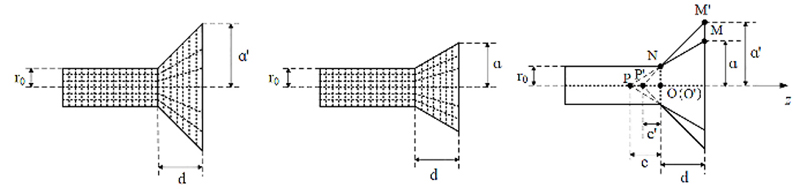
Figure 1: Coordinate transformation scheme of the proposed horn antenna ( cross-section): (a) TO-based horn antenna in the physical space, (b) transformation target of the TO-based horn antenna in the virtual space, which is a standard horn antenna, and (c) overlapping cross-sections of the two antennas.
Following the approach in [19], the mapping from the virtual coordinate system to the physical coordinate system dictates a frustum cone space with the following radius-dependent, anisotropic relative permittivity and permeability:
| (2) |
| (3) |
| (4) |
Equations (2)-(4) show that all permittivity and permeability components are positive, which are much easier to realize through artificial metamaterials than through negative material components.
The antenna geometric dimensions in this paper are as follows: mm, mm, mm, and mm.
Among many kinds of metamaterials [20, 21], we chose the classical SRRs to realize the prescribed value. The substrate used in the SRRs is FR-4, whose permittivity is 4.3 and loss tangent is 0.017. On the top and bottom sides of the FR-4 substrate, the printed split rings are oriented with a rotational angle of , to reduce the polarization sensitivity of the metamaterial, as shown in Fig. 2 (a,b).
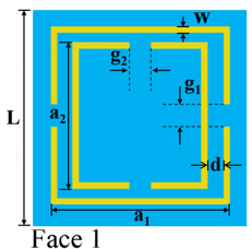
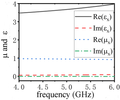
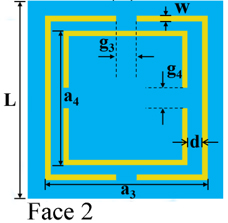
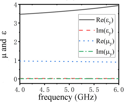
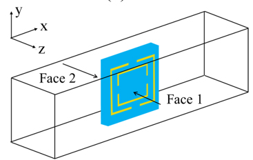
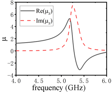
Figure 2: (a) Geometry of the metamaterial unit-cell face 1, (b) geometry of the metamaterial unit-cell face 2, (c) unit-cell simulation scheme, (d-f) retrieved constitutive parameters of layer 11, (d) , , (e) , , and (f) .
The unit cells of the metamaterial were designed with the commercial software CST Microwave Studio. The operating frequency is 5 GHz. With the constitutive parameters’ retrieval algorithm [22], the anisotropic constitutive parameters can be obtained. For example, to retrieve , we first set the unit cell model as in Fig. 2 (c), and assign the periodic boundary conditions to the lateral walls in both the - and -directions. Then a TM polarized plane wave incidence from the -direction (with the magnetic field along the -direction) was introduced. Then can be retrieved from the simulated parameters. and values can be obtained similarly. To keep this paper concise, only the simulation result of layer 11 was plotted as an example in Fig. 2 (d-f). The retrieved , , and coincide with the design target (2)-(4) at 5 GHz. The imaginary parts of and are 0. It is noted that the real parts of and differ from the design target (2) and (3), which may cause the difference between the measurement based on the SRR realized model and the numerical results based on the TO dictated model. However, this difference is inevitable because of the existence of the dielectric substrate in the unit cell. Similar situations exist in the other layers. Therefore, it is necessary to evaluate the metamaterials-based design.
In Table 1, we list the structure parameters of SRRs and the SRR-realized of each layer. From Table 1, it is seen that the permeability of every layer changes gradually. Thus, it is expected that the SRR realized medium will not introduce significant reflection.
Table 1: Size and of every layer
| Layer | Z(mm) | L(mm) | d(mm) | w(mm) | Re() |
| 1 | 0 | 0 | 0 | 0 | 1 |
| 2 | 10 | 5 | 0.3 | 0.1 | 1.28 |
| 3 | 20 | 5 | 0.1 | 0.1 | 1.62 |
| 4 | 30 | 5 | 0.1 | 0.1 | 1.62 |
| 5 | 40 | 5 | 0.1 | 0.2 | 1.85 |
| 6 | 50 | 5 | 0.4 | 0.3 | 2.01 |
| 7 | 60 | 5 | 0.3 | 0.2 | 2.46 |
| 8 | 70 | 5 | 0.3 | 0.2 | 2.46 |
| 9 | 80 | 5 | 0.3 | 0.2 | 2.46 |
| 10 | 90 | 5 | 0.4 | 0.3 | 2.76 |
| 11 | 100 | 5 | 0.4 | 0.3 | 2.76 |
| 12 | 110 | 5 | 0.2 | 0.4 | 2.91 |
| 13 | 120 | 5 | 0.1 | 0.3 | 3.02 |
| 14 | 130 | 5 | 0.1 | 0.2 | 3.12 |
| 15 | 140 | 5 | 0.1 | 0.1 | 3.21 |
| 16 | 150 | 5 | 0.5 | 0.2 | 3.29 |
| 17 | 160 | 5 | 0.1 | 0.5 | 3.38 |
| 18 | 170 | 5 | 0.3 | 0.4 | 3.51 |
| 19 | 180 | 5 | 0.3 | 0.4 | 3.51 |
| 20 | 190 | 5 | 0.1 | 0.4 | 3.67 |
| 21 | 200 | 5 | 0.4 | 0.3 | 3.77 |
| 22 | 210 | 5 | 0.2 | 0.3 | 3.80 |
| 23 | 220 | 5 | 0.2 | 0.3 | 3.80 |
| 24 | 230 | 5 | 0.3 | 0.2 | 3.91 |
| 25 | 240 | 5 | 0.2 | 0.3 | 4.04 |
III. FULL-WAVE SIMULATIONS
In this section, the proposed antenna with the TO-based filing realized by the SRR material is investigated using CST Microwave Studio. Limited by computing resources, the model of the horn antenna is only filled with the first five layers of SRR filling. A reference antenna is obtained by simply removing the SRR filling from the proposed antenna. The simulated S11 results are plotted in Fig. 3. Due to the reflection between each layer in the SRR insertion, the proposed antenna has an impedance band of 4.6-5.5 GHz (a relative bandwidth of 18%), which is narrower than the unfilled antenna.
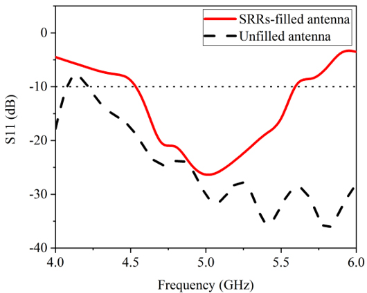
Figure 3: Simulated S11 of the SRR-filled horn antenna and unfilled horn antenna.
OAM waves of mode are exited in the feeding waveguides of the two antennas. Observation planes are defined away from the radiation aperture of each horn antenna. The simulated amplitude of E-field is shown in Figs. 4 (a) and (c). An apparent low amplitude zone can be found in the beam center, which is a characteristic feature of the OAM beam. Additionally, we can see that the energy is more focused for the cases of the SRR-filled antennas. In all cases, an obvious spiral phase distribution corresponding to OAM of order can be observed, as shown in Figs. 4 (b) and (d).
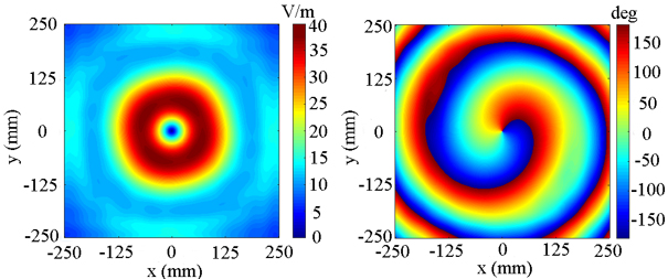
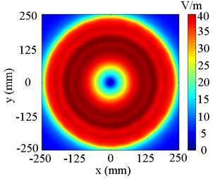
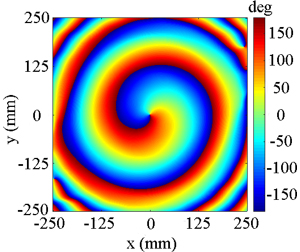
Figure 4: Measured amplitude distribution and phase pattern: (a,b) the SRR-filled horn antenna and (c,d) the unfilled horn antenna.
From the above phase information, OAM mode purities are calculated on different concentric integration contours on the observation planes [23]. These contours are indicated by radius in Fig. 5. It shows that the SRR-filled horn antenna has a mode purity comparable to that of the unfilled antenna, indicating that the layered metamaterial does not degrade the mode purity.
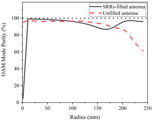
Figure 5: OAM mode purity of the antennas.
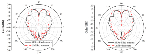
Figure 6: Simulated gain of the antenna: (a) E-plane and (b) H-plane.
Table 2: Simulated main lobe angle for the L 1 OAM beam
| E-plane | H-plane | |||
| Cases | Angle( ) | Gain(dBi) | Angle() | Gain(dBi) |
| SRR-filledantenna | 17 | 8.9 | 17 | 8.9 |
| Unfilledantenna | 23.5 | 11.6 | 23.5 | 11.6 |
The simulated gains of the antennas at 5 GHz are plotted in Fig. 6, with the main lobe angle summarized in Table 2. In the SRR-filled antenna, there is a reduction of in the main lobe angle in the E-plane and H-plane compared with the unfilled antenna. In addition, it can be seen that the maximum gain of the SRR-filled antenna is lower than the unfilled one. This is attributed to the lossy FR-4 substrate used in the filling.
IV. EXPERIMENTAL RESULTS
To verify the design, the horn antenna, as illustrated in Fig. 1, was fabricated. Its photograph is shown in Fig. 7 (a). Two SMA connectors are used to feed the horn antenna with equal magnitude and a phase difference to generate the OAM mode. The first 11 layers of metamaterial in Table 1 were fabricated, as shown in Fig. 7 (b).
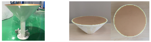
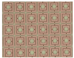
Figure 7: (a) Fabricated horn antenna, (b) fabricated metamaterial, and (c) unit cell layout of the metamaterial.
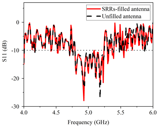
Figure 8: Measurement results of S11 from the antennas.
First, the reflection coefficients of the SRR-filled antenna and the unfilled antenna are measured (Fig. 8). The reflection coefficients for the two antennas are comparable with an operating band centered at 5 GHz, demonstrating that TO-based filling does not introduce extra reflection.
The near-field measurement setup is shown in Fig. 9. An open waveguide is used as a probe to measure the phase and field intensity. Scanning is performed in a planar zone for both horizontal polarization and vertical polarization.
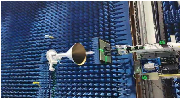
Figure 9: Near-field measurement setup.
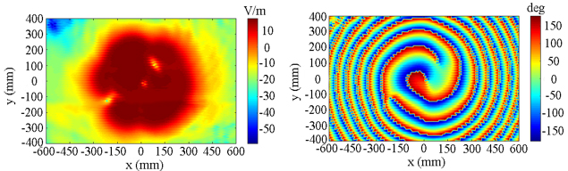
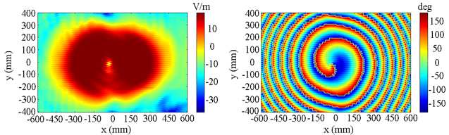
Figure 10: Measured amplitude distribution and phase pattern: (a) amplitude, SRR-filled antenna, (b) phase pattern, SRR-filled antenna, (c) amplitude, unfilled antenna, and (d) phase pattern, unfilled antenna.
For all the antennas to be scanned, observation planes are defined away from the radiation aperture of the horns. The measured amplitude distribution and phase pattern are shown in Fig. 10. Similar to the simulation results in Fig. 4, an OAM null zone can be found in the beam center. Additionally, we can see that the energy distribution is in a better regularly circular form for the case of the SRR-filled antenna. Obvious spiral phase distributions corresponding to OAM of order can be observed for both antennas, which is consistent with the simulation results in Fig. 4. Only the H-polarization measurement results are plotted in Fig. 10. Similar results for the V-polarization can be obtained and are not plotted here.
From the phase information, OAM mode purities are calculated again as a function of the contour radius , as shown in Fig. 11. It shows that the SRR-filled horn antenna has a mode purity of over 80% in the range of with a maximum of 88.9% reached at . It is comparable to the mode purity of the unfilled antenna.
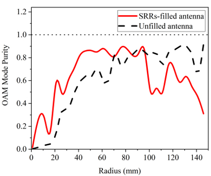
Figure 11: OAM mode purity of the antennas.
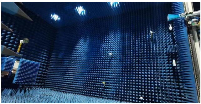
Figure 12: Far-field measurement setup.
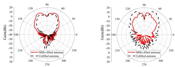
Figure 13: Gain of the antennas: (a) E-plane and (b) H-plane.
The gains of the antennas are measured with the system setup shown in Fig. 12. The measured gains at 5 GHz are depicted in Fig. 13. The key information of the main lobe angle is summarized in Table 3.
Compared with the unfilled horn antenna, the SRR-filled antenna has a reduction of on the main lobe angle in the H-plane. However, in the E-plane, the lobe angles of the two antennas are similar.
Table 3: Measured main lobe angle for the L 1 OAM beam
| E-plane | H-plane | |
| Cases | Angle () | Angle () |
| SRR-filled antenna | 20 | 11 |
| Unfilled antenna | 20 | 24 |
Further investigation shows the different performance in measurement and simulation origins from the feeding of the antennas. In the simulations, ideal waveguide ports are defined at the end of the circular waveguides and the antennas are circular polarized. However, as the fabricated antennas are fed with a pair of waveguide ports, the antennas become linearly polarized and, thus, the gains in E- and H-planes lost symmetry. Table 4 shows the comparison of the proposed transformation optics metasurface (TOMS) and other designs, including Huygens’ metasurface (HMS) [11] and concentric uniform circular array (CUCA) [15]. We know the proposed work can reduce the cone-apex angle of the beam energy, while maintaining high OAM purity.
Table 4: Comparison with other designs
| Ref. | [11] | [15] | This Work |
| Type | HMS | CUCA | TOMS |
| Angle | - | 15 | 11 |
| OAM purity | 84% | - | 90.5% |
To conclude, the reduction on main lobe angle in the H-plane measurement results show that the layered SRR-filled antenna can generate focused OAM beams.
In this paper, we only consider the TE polarized wave. For the TM wave, the metamaterial must be designed with desirable , while can be arbitrary. The desirable can be realized by wire medium and be explored in the future.
V. CONCLUSION
In this study, a SRR-filled horn antenna is proposed to generate a focused OAM beam. Transformation optics was utilized to obtain an inhomogeneous transformation medium for focusing the OAM beam. To validate the proposed approach, we fabricated and measured the proposed antenna based on a double-sided split ring resonator. By inserting SRR-filling, the OAM mode purity is well-preserved, and the OAM main lobe angle can be reduced by , which agrees with the simulation results. The focused OAM beam can be a preferable feature in the OAM wireless communication systems.
ACKNOWLEDGMENT
This work is supported by BIT-BRFFR Joint Research Program, under Grant No. BITBLR2020015.
REFERENCES
[1] S. M. Mohammadi, L. K. Daldorff, J. E. Bergman, R. L. Karlsson, B. Thide, K. Forozesh, T. D. Carozzi, and B. Isham, “Orbital angular momentum in radio—a system study,” IEEE Trans. Antennas Propag., vol. 58, no. 2, pp. 565-572, 2009.
[2] Y. Shuang, H. Zhao, W. Ji, T. J. Cui, and L. Li, “Programmable high-order OAM-carrying beams for direct-modulation wireless communications,” IEEE J. Emerg. Sel. Topics Circuits Syst., vol. 10, no. 1, pp. 29-37, 2020.
[3] Y. Yagi, H. Sasaki, T. Yamada, and D. Lee, “200 Gb/s wireless transmission using dual-polarized OAM-MIMO multiplexing with uniform circular array on 28 GHz band,” IEEE Antennas Wireless Propag. Lett., vol. 20, no. 5, pp. 833-837,2021.
[4] H. Yang, S. Zheng, H. Zhang, T. He, N. Li, Z. Yang, Z. Lyu, Y. He, L. Zhang, and X. Yu, “Metasurface-based high-speed photonic THz OAM communication system,” Journal of Lightwave Technology, vol. 42, no. 15, pp. 5080-5087, 2024.
[5] Z. Luo, Y. Liao, and M. Xing, “Target imaging and anti-jamming with frequency agile OAM radar,” IEEE Geoscience and Remote Sensing Letters, vol. 21, pp. 1-5, 2024.
[6] J. Chen, Z. Liang, K. Liu, J. Liu, Y. Jing, and B. Xiang, “Phase-encoding truncated orbital angular momentum modes for high-security and high-capacity information encryption,” Journal of Lightwave Technology, vol. 42, no. 10, pp. 3677-3683, 2024.
[7] S. M. Mohammadi, L. K. Daldorff, K. Forozesh, B. Thide, J. E. Bergman, B. Isham, R. Karlsson, and T. Carozzi, “Orbital angular momentum in radio: Measurement methods,” Radio Science, vol. 45, no. 4, pp. 1-14, 2010.
[8] R. Lyu, W. Cheng, W. Zhang, and F. Qin, “OAM-NFC: A short-range high capacity transmission scheme,” in ICC 2020-2020 IEEE International Conference on Communications (ICC), Dublin, pp. 1-6, 2020.
[9] Y. Yao, X. Liang, W. Zhu, J. Geng, and R. Jin, “Experiments of orbital angular momentum phase properties for long-distance transmission,” IEEE Access, vol. 7, pp. 62689-62694, 2019.
[10] H. Liu, H. Xue, Y. Liu, Q. Feng, and L. Li, “Generation of high-order Bessel orbital angular momentum vortex beam using a single-layer reflective metasurface,” IEEE Access, vol. 8, pp. 126504-126510, 2020.
[11] D. Su, H. Zhang, H. Xiao, W. Song, H. Xiong, D. Xiao, and X. Wang, “Generation of enhanced focused airy orbital angular momentum beam with metal-only Huygens’ metasurface,” IEEE Transactions on Circuits and Systems II: Express Briefs, vol. 71, no. 8, pp. 3875-3879, 2024.
[12] J. Guo, C. Shen, J. Hu, Y. Zhu, C. Zhang, and S. Wei, “Generation of power-exponent-phase vortex beam arrays based on all-dielectric metasurfaces,” IEEE Photonics Journal,” vol. 16, no. 2, pp. 1-6, 2024.
[13] R. Xi, L. Li, and T. Zhang, “A high-gain orbital angular momentum antenna array based on parasitic composite slabs,” in 2018 International Applied Computational Electromagnetics Society Symposium - China (ACES), Beijing, China, pp. 1-2, 2018.
[14] M. K. T. Al-Nuaimi, W. G. Whittow, G.-L. Huang, and R.-S. Chen,“ Generation of narrow divergence angle OAM beams for mmwave communication links using metasurface,” in 2024 18th European Conference on Antennas and Propagation (EuCAP), Glasgow, UK, pp. 1-5, 2024.
[15] S. Guo, Z. He, and R. Chen, “Generation and numerical simulation of the focused OAM beams,” Engineering Analysis with Boundary Elements, vol. 135, pp. 359-368, 2022.
[16] J. Ren and K. W. Leung, “Generation of high-purity millimeter-wave orbital angular momentum modes using horn antenna: theory and implementation,” arXiv preprint arXiv:1710.00035, 2017.
[17] J.-T. Jing, W. Song, and X.-Q. Sheng, “Transformation optics-based horn antenna for focusing orbital angular momentum beams,” International Journal of RF and Microwave Computer-Aided Engineering, vol. 30, no. 11, p. e22408, 2020.
[18] J. B. Pendry, D. Schurig, and D. R. Smith, “Controlling electromagnetic fields,” Science, vol. 312, no. 5781, pp. 1780-1782, 2006.
[19] J. Kraus and R. Marhefka, Antennas: For All Applications. Maidenhead: McGraw-Hill Publishing, 2004.
[20] A. Yelizarov, I. Nazarov, A. Skuridin, and E. Zakirova, “Computer model of a frequency-selective surface on mushroom-shaped metamaterial,” in 2020 Systems of Signal Synchronization, Generating and Processing in Telecommunications (SYNCHROINFO), pp. 1-4, 2020.
[21] H. Sedghi and H. Rezazadeh, “A broadband asymmetric microwave metamaterial based on LC and standing-wave resonances,” Physics Letters A, vol. 384, no. 29, p. 126758, 2020.
[22] X. Chen, T. M. Grzegorczyk, B.-I. Wu, J. Pacheco Jr, and J. A. Kong, “Robust method to retrieve the constitutive effective parameters of metamaterials,” Physical Review E, vol. 70, no. 1, p. 016608, 2004.
[23] T. Yuan, Y. Cheng, H. Wang, and Y. Qin, “Mode characteristics of vortical radio wave generated by circular phased array: Theoretical and experimental results,” IEEE Trans. Antennas Propag., vol. 65, no. 2, pp. 688-695, 2017.
BIOGRAPHIES

Jia-Tong Jing received the B.E., M.S. degrees from Beijing Institute of Technology, Beijing, China, in 2018 and 2021. He is currently pursuing the Ph.D. degree in Institute of Radio Frequency Technology and Software from Beijing Institute of Technology. His current research interests include metamaterial and computational electromagnetics.

Wei Song received the B.S. degree from Northeastern University, Shenyang, China, in 2002, and the M.S. and Ph.D. degrees from Queen Mary University of London, UK, in 2003 and 2008, respectively. She is currently an Associate Professor with the School of Information and Electronics, Beijing Institute of Technology, Beijing, China. She has authored or co-authored over 20 papers in refereed journals and international conferences, and has co-authored a monograph in computational electromagnetics. Her current research interests include high-performance methods in computational electromagnetics, EM property analysis, and metamaterial-based antenna design.

Xin-Qing Shengreceived the B.S., M.S., and Ph.D. degrees from the University of Science and Technology of China (USTC), Hefei, China, in 1991, 1994, and 1996, respectively. Sheng is a Chang-Jiang Professor of the School of Information and Electronic at the Beijing Institute of Technology. Sheng has authored and co-authored over 150 papers in refereed journals, and three books: Essentials of Computational Electromagnetics(Singapore: IEEE Press-Wiley, 2012), A Brief Treatise on Computational Electromagnetics(Beijing: Science Press, 2004), and A Treatise on Electromagnetic Wave(Beijing: Science Press, 2007). Sheng has authored SINOCOM, a simulation software for scattering by complex targets. His research interests include computational electromagnetics, scattering and antenna analysis, electromagnetic compatibility, and microwave imaging.
ACES JOURNAL, Vol. 39, No. 9, 794–800
doi: 10.13052/2024.ACES.J.390905
© 2024 River Publishers