Study on MPI-based Parallel FDTD Method of Moving Target Coated with Time-varying Plasma
Hai-Yan Li, Xian-Min Guo, Yong Bo, Wei Chen, Li-Xia Yang, Zhi-Xiang Huang, Jia-Chen Wang, and Xin-Jie Duan
1Information Materials and Intelligent Sensing Laboratory of Anhui Province
Anhui University, Hefei, 230601, China
p21201066@stu.ahu.edu.cn, p21301162@stu.ahu.edu.cn, boyong@ahu.edu.cn, chenwei1704@126.com, lixiayang@yeah.net, zxhuang@ahu.edu.cn, p02114038@stu.ahu.edu.cn, 1392626588@qq.com
2East China Research Institute of Electronic Engineering
Hefei, China
boyong@ahu.edu.cn
Submitted On: July 27, 2023; Accepted On: December 12, 2023
ABSTRACT
Analyzing the electromagnetic (EM) scattering properties of high-speed moving objects is a hot research topic in recent years. However, EM calculations for high-speed moving targets always involve challenges of high computational complexity and low computational efficiency. In this paper, we integrate the Message Passing Interface (MPI) based parallel finite difference time domain (FDTD) method and Lorentz transformation to calculate the EM scattering of a moving metal sphere coated with time-varying plasma. Subsequently, by comparing the outcomes of the proposed Parallel FDTD approach with the serial computing results, the validity of the Parallel FDTD method is validated. Additionally, for a moving and time-varying plasma sheath coated object, the impacts of the time-varying parameters and plasma parameters on the EM scattering properties are investigated using the Parallel FDTD approach. The results indicated that the MPI-Based Parallel FDTD approach displays almost identical precision as the serial approach. Furthermore, the Parallel FDTD approach can enhance computation speed and significantly reduce the computation time.
Index Terms: electromagnetic (EM) properties, Lorentz transformation, Message Passing Interface (MPI), moving target, Parallel finite difference time domain (FDTD) method, time-varying plasma.
I. INTRODUCTION
Research on the electromagnetic (EM) scattering of high-speed moving targets is a popular research topic due to its broad range of applications in identifying moving targets and exploring deep space [1–8] such as detection and identification of moving satellites, aircraft, and ships. Furthermore, investigating the interaction between EM and moving targets is crucial for understanding the propagation principle of EM waves in complex media and improving the performance of wireless communication and radar systems. Harfoush et al. [4] utilized relativistic boundary conditions (RBC) based on the finite difference time domain (FDTD) approach to investigate the scattering field from one-dimensional (1-D) and two-dimensional (2-D) conducting moving objects. Zheng et al. [5] proposed the representation of the incident wave in the Lorentz-FDTD method and analyzed the double-Doppler effect from a moving dielectric target. Zhang and Nie [6] proposed the combined method of the RBC and the FDTD to calculate the radar cross-section (RCS) of a moving metal target. Zheng et al. [7] analyzed the scattered fields from a moving conducting target, and the results show that the amplitude and frequency of scattered fields are modulated by the velocity of the target. Zheng et al. [8] studied the micro-motion state of a moving target using the Lorentz-FDTD algorithm, and discussed the effect of the micro-motion state on EM echo. The EM scattering of high-speed moving dielectric or metallic targets has been extensively analyzed. However, there is still a lack of research on the EM scattering analysis of moving dispersive media.
The FDTD method is a widely used approach for solving EM problems and has been extensively applied in EM scattering calculations [9–12]. However, the calculation accuracy and stability are limited by the spatial and temporal discretization sizes in FDTD. Therefore, traditional serial FDTD methods are inadequate for large-scale EM calculations, as they cannot meet the requirements of high computing speed and large memory computation. To address these issues, an increasing number of researchers are adopting the FDTD method combined with parallel calculation methods for EM scattering calculations to achieve higher computational efficiency. Varadaraian and Mittra [13] utilized Parallel Virtual Machine (PVM) to implement Parallel FDTD simulations and investigated the three-dimensional (3-D) rectangular resonant cavity problem. Guiffaut and Mahdjoubi [14] developed a Parallel FDTD computations method based on the Message Passing Interface (MPI). Stefanski and Drysdale [15] were the first to implement parallel acceleration in the EM problem calculation of the anisotropic medium with alternating direction implicit FDTD (ADI-FDTD) method. Duan et al. [16] implemented a high-performance Parallel FDTD computation on multi-core of PC-Cluster using Winsock and multi-threaded method, and the results show that this method can significantly speed up the computation as well as improve the computation efficiency. Mao et al. [17] analyzed two different moving window FDTD (MW-FDTD) parallel approaches to simulate the EM propagation in tunnels, and both methods have high accuracy. Chakarothai et al. [18] developed a large-scale Parallel FDTD method using the GPU cluster of the TSUBAME system for numerical exposure of a human body to EM fields. Lei et al. [19] studied the scattering properties of electrically large coated objects, such as warships and planes, by employing the MPI-Based Parallel FDTD approach. Yang and colleagues proposed a 3-D parallel anisotropic medium FDTD method for the EM computations in anisotropic media [20–22]. Duan et al. [23] introduced the parallel Auxiliary Differential Equation FDTD (ADE-FDTD) method to solve the EM problems of plasma, which can reduce calculation time. Wang et al. [24] proposed a novel conformal surface current approach based on the Parallel FDTD method, providing a potential solution for handling large-scale EM calculation problems. Shi et al. [25] investigated a hybrid Parallel FDTD algorithm to solve EM scattering calculations of electrically large objects, and the results indicate that this approach can improve computing speed.
When applying the Lorentz-FDTD method to investigate time-varying and moving dispersive medium targets, the considerable computational effort is required for EM calculation. Therefore, the application of parallel Lorentz-FDTD methods for analyzing time-varying and moving plasmas is meaningful. Considering that the plasma sheath generated around high-speed moving targets is always time-varying, this paper combines the MPI-Based Parallel FDTD method with Lorentz transformation to calculate the EM scattering properties of a moving object coated with time-varying plasma. By integrating parallel processing techniques, the FDTD method can significantly accelerate the computation process and reduce computation time, thereby expanding the scope of applications for numerical simulation methods.
II. METHOD
In this section, the Lorentz transformation, Parallel FDTD method, and ADE-FDTD method will bediscussed.
A. Lorentz transformation
In the analysis of EM scattering problems from moving targets, as shown in Fig. 1, two reference frames are considered: a moving reference frame and a laboratory reference frame . Here, the target moves at the speed in the system , and the system moves at the same speed relative to system . Thus, the target is stationary in the system . Due to relativistic covariance, EM scattering problem of the moving target can be transformed into the moving reference frame for a solution.
When performing the EM calculation for a moving dispersive medium target, the time and space increment need to be transformed between the reference frame and . Assuming the target moving at the velocity , the time and space increment transformation formulas between these two reference frames are as shownin (A.)–(4):
| (1) |
| (2) |
| (3) |
| (4) |
where , , and is the speed of light in free space, is the speed of the target. , . The denotes the angel between and axis, and the denotes the angle between the projection of on and axis.
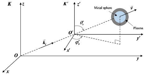
Figure 1: The two reference frames of Lorentz-FDTD.
When converting the EM problems to the reference frame , the incident wave defined in the reference frame also needs to be introduced into the reference frame . According to the principle of the phase invariance of Lorentz transformation in (5), the amplitude and frequency of the incident wave in the reference frame are obtained by (6)–(7):
| (5) |
| (6) | ||||
| (7) |
where denotes the frequency and amplitude of the incident wave in the reference frame . The is the angle between the incident wave vector and the axis, and is the angle between the projection of the incident wave vector in the plane and the axis. And is the angle between the incident electric field and the velocity of the target, .
After introducing the incident wave into the reference frame , the EM scattered fields can be calculated using the FDTD method. Since the EM fields in the two reference frames follow the Lorentz transformation [26], the EM scattered field components can be derived by performing the inverse Lorentz transformation. The transformation formulas are shown in (8)–(9):
| E | (8) | |||
| B | (9) |
B. Auxiliary Differential Equation (ADE)-FDTD method
Maxwell’s equations in the collision non-magnetized plasma are given as follows [9]:
| (10) | ||||
| (11) | ||||
| (12) |
where the frequency domain expression for the polarization current is:
| (13) |
According to (12), the intrinsic relationship in the frequency domain for the dielectric coefficient is:
| (14) |
where denotes the dielectric coefficient of the plasma, and is the polarization rate of the plasma.
The polarization rate of the Drude medium is described as follows:
| (15) |
Substituting equation (15) into (13):
| (16) |
By applying the operator conversion relation from the frequency domain to the time domain [27], equation (16) transforms to:
| (17) |
By integrating both sides of equation (17), the iterative formula of shown in equation (18) is obtained after discretizing the differential equation. The coefficients are presented in equation (19):
| (18) |
The coefficient in (18) is shown in (19):
| (19) |
Substituting equation (18) into (13), and then the iterative formula for electric field is obtained:
| (20) |
| (21) |
For EM scattering problems, a connecting boundary is typically introduced within the FDTD computational region. When FDTD is applied to scattered field calculations, the FDTD computation area is divided into a total field region and a scattered field region. To model EM problems in unbounded space within a limited computational region, absorbing boundary conditions are necessary on the truncated boundaries of the computational region. To obtain the scattered field outside of the computational domain, using the equivalence principle, the far-zone scattered field can be obtained from the near-zone scattered field by at the output boundary. The division of the FDTD computational region is shown in Fig. 2.
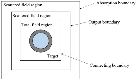
Figure 2: The division of the FDTD computational region.
C. Parallel FDTD method
In this paper, a combined mode of master-slave and peer-to-peer modes are adopted for the calculation of EM scattering from a moving metal coated with time-varying plasma. The detailed flowcharts of the master process and slave processes are shown in Figs. 4 and 5, respectively. By using the Parallel FDTD method, we can significantly improve resource utilization and reduce the calculation time, especially when the hardware resources are limited.
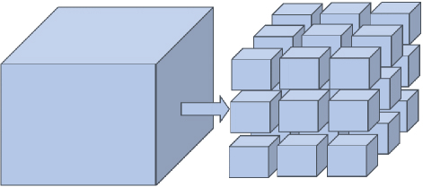
Figure 3: Region divide using the 3-D mode.
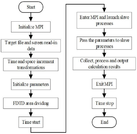
Figure 4: The flowchart of the master process in Parallel FDTD method.
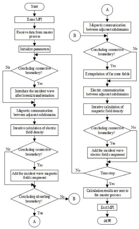
Figure 5: The flowchart of the slave processes in Parallel FDTD method.
In the master process, prior to employing the Parallel FDTD method for EM calculations, the FDTD calculation area is initially divided into sub-domains. A 3-D region dividing approach is adopted in this paper, as illustrated in Fig. 3. When the region is divided into sub-domains, each sub-domain can exchange information with one another.
As Fig. 4 illustrates, the master process is primarily responsible for assigning computation tasks to each slave process and collecting and processing data once all slave processes have completed their computation tasks.
As shown in Fig. 5, the slave processes are accountable for receiving the tasks assigned by the master process. Each process performs the iterative update of EM fields using the ADE-FDTD method, along with the computation of the connection boundary, absorption boundary, and output boundary. Once all processes have completed their calculation tasks, the calculation results are transmitted to the master process.
III. NUMERICAL RESULTS
A. Validation of parallel Lorentz-FDTD method
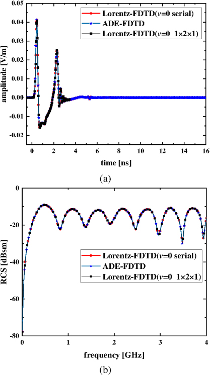
Figure 6: The validation of parallel Lorentz-FDTD method: (a) scattering fields in the time domain and (b) monostatic RCS.
As an example, the scattered fields in the time domain and the monostatic RCS from a plasma sphere are calculated. The radius of the plasma sphere is 10 cm. In this section, the serial calculation results are compared with the parallel calculation results and the results of the plasma sphere with m/s calculated by the parallel Lorentz-FDTD are compared with the results calculated using the ADE-FDTD method.
The space increment is set as m, and the time increment satisfies the Courant stability criterion: , c is the is the speed of light in free space. The incident direction is 0, 0 and 0. The receive angle of the scattered wave is 180, 180.
As shown in Figs. 6 (a) and (b), the corresponding time-domain scattered field and RCS results calculated with serial and parallel methods are presented when the target velocity is 0 m/s. In addition, the results calculated by the parallel Lorentz-FDTD method when are also compared with the conventional ADE-FDTD results. From Figs. 6 (a) and (b), it can be seen that the serial and parallel results agree well, and the results of the Lorentz-FDTD method are also consistent with the conventional ADE-FDTD method, so the validity and accuracy of the parallel Lorentz-FDTD method is verified.
Figure 7 presents the monostatic RCS results calculated using the serial and parallel method when the plasma sphere is moving at 0.01c. The results in Fig. 7 demonstrate that the serial and parallel calculations are in good agreement. Thus, the Parallel FDTD method has almost the same precision as the serial computation when calculating the EM scattering from moving targets.
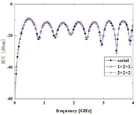
Figure 7: Monostatic RCS of the plasma sphere moving at 0.01c.
B. EM scattering properties of moving metal sphere coated time-varying plasma sheath
In the simulation of this section, the EM scattering properties from a moving 3-D metal sphere coated with time-varying plasma are calculated and analyzed. A Gaussian pulse wave with an amplitude of 1 V/m, and , 4GHz, and . The amplitude of the incident wave in the frame can be derived using the Lorentz transformation. The formula of the incident wave source in the frame is as show in (22). The space grid is set as m, and the time increment satisfies the Courant stability criterion: . The radius of the metal sphere is 40, and the thickness of the plasma is 5. The direction of the incident wave is 90 and 90:
| (22) |
| (23) |
where is the amplitude of incident wave in the system , and denotes the dot product of the unit vector of the incident wave and the unit vector of the speed.
The time-varying electron density of the plasma is described as follows:
| (24) |
where = 310m denotes the average electron density of the time-varying plasma, denotes the variation range of electron density, and = 80 MHz is the time-varying frequency.
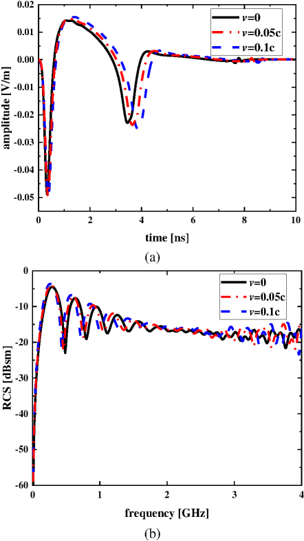
Figure 8: Scattered field results of metal sphere coated with time-varying plasma at different velocities: (a) scattered fields in the time domain and (b) monostatic RCS.
Figure 8 (a) displays the scattering fields in the time domain for targets moving at velocities of , 0.05c, and 0.1c. The results indicate that when the target’s motion direction is aligned with the incident direction, the scattered wave experiences a delay in the time domain. Moreover, the greater the velocity, the greater the delay. Surprisingly, the amplitude of the scattered wave increases slightly with an increase in velocity. As shown in Fig. 8 (b), a monostatic RCS is observed with a shift towards the low-frequency band if the target moves along the incident direction (v0). Moreover, the higher the speed, the more evident the RCS shift towards the lower frequency band.
Table 1: The calculation time comparison between the parallel Lorentz-FDTD method and the serial method
| (m/s) | TimeSteps | SerialTime (s) | ParallelTime (s) | |
| 0 | 6500 | 4002.7243 | 812.7958 | 4.925 |
| 8000 | 5479.5720 | 999.8317 | 5.480 | |
| 10000 | 8847.1129 | 1360.779 | 6.502 | |
| 0.05 | 6500 | 3742.7816 | 1044.247 | 3.584 |
| 8000 | 4240.9656 | 1064.220 | 3.985 | |
| 10000 | 5951.7948 | 1183.002 | 5.031 | |
| 0.1 | 6500 | 4022.4639 | 1090.065 | 3.690 |
| 8000 | 4196.1614 | 1104.651 | 3.799 | |
| 10000 | 5291.8946 | 1219.548 | 4.339 |
Table 1 presents the serial and parallel computing times for three different speeds when the partitioning mode is the same (both 222) but the total running time steps are different. Besides, the parallel acceleration ratio () was calculated according to the serial and parallel computing times. The results in Table 1 indicate that, for three different motion speeds, the simulation time used by the parallel method is different when the total simulation time step is different but the target motion speed and the computational region are divided in the same way. Moreover, it can be seen from the data in Table 1 that the larger the total running time step, the higher the parallel acceleration ratio. A larger time step indicates a higher computational complexity. This implies that the Parallel FDTD algorithm for EM scattering calculations of moving targets coated with time-varying plasma sheath computes faster and more efficient when the computational complexity is higher.
Next, the effect of different plasma time-varying parameters on target EM scattering will be discussed, respectively.
Figure 9 displays the monostatic RCS for different average electron densities of the time-varying plasma when the target moves along the axis at a velocity of . The partitioning mode is set as 121. From Fig. 9, it can be seen that as the average electron density of time-varying plasma increases, the RCS also increases continuously. This is because a higher average electron density corresponds a higher the cutoff frequency of the plasma and stronger ability of the plasma sheath to backscatter the EM waves. This is because the time-varying characteristic of the electron density in the plasma sheath causes the cutoff frequency to vary with time, resulting in oscillations in the backward RCS.
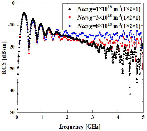
Figure 9: Monostatic RCS of metal sphere coated with time-varying plasma under different average electron densities .
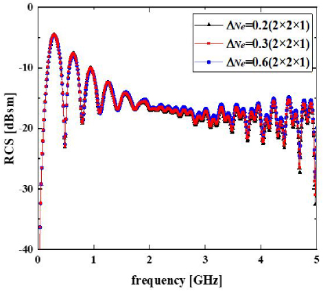
Figure 10: Monostatic RCS of metal sphere coated with time-varying plasma under different .
Figure 10 presents the monostatic RCS for different variation ranges of electron density of the time-varying plasma . The partitioning mode is set as 221. As observed in Fig. 10, the monostatic RCS increases slightly with . The main reason is that when changes, the range of variation in plasma electron density is small. Therefore, the reflection ability of the plasma sheath on the EM wave has little effect, which leading to minimal changes in the backward RCS.
Figure 11 displays the monostatic RCS for different time-varying frequencies of the plasma. The total time step is set as 40000, and we choose the partitioning mode 222 to speed up the simulation time. As shown in Fig. 11, it can be seen that monostatic RCS remains nearly invariant with the time-varying frequency . This is because the average electron density remains unchanged in each case. Additionally, due to the time-varying frequency, the target has time-varying scattering characteristics for EM waves of different frequencies, which will impact the RCS of the target.
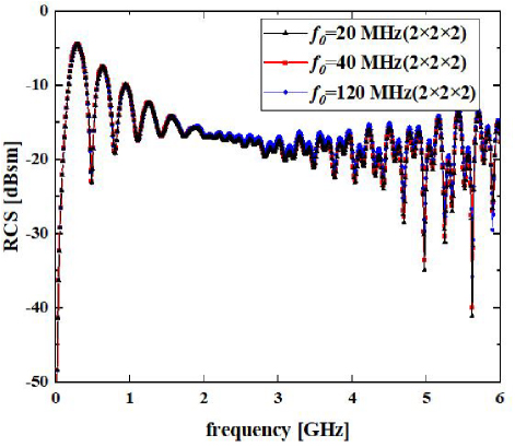
Figure 11: Monostatic RCS of metal sphere coated with time-varying plasma under different time-varying frequencies .
Table 2 presents the calculation time and speedup ratio () of the Parallel FDTD algorithm for different partitioning modes at different time-varying frequencies, when the time steps are all set to 40000 steps. As shown in Table 2, the calculation time of the parallel method varies for different partitioning methods, yet the program running speed is significantly improved.
Besides, as can be seen from the data in Table 2, the computation speed of a parallel approach is approximately seven times faster than that of a single process. However, as the number of parallel processes increases, the speed of parallel computing does not continue to increase; instead, it shows a relatively gradual decline as the number of processes increases. This is mainly because as the number of processes increases, the communication cost becomes higher. The number of grids needed to transfer data also increases, and the additional waiting time between the processes will continue to increase. This results in the parallel efficiency becoming lower and lower.
Table 2: The corresponding acceleration ratio of different parallel schemes under three time-varying frequencies
(MHz) |
Process Number | PartitioningMode | ParallelTime (s) | |
| 20 | 1 | 111 | 33763.2820 | |
| 4 | 221 | 6078.145 | 5.555 | |
| 12 | 322 | 5679.412 | 5.945 | |
| 16 | 441 | 4968.570 | 6.795 | |
| 24 | 432 | 4680.543 | 7.214 | |
| 27 | 333 | 4814.949 | 7.012 | |
| 32 | 442 | 4931.247 | 6.847 | |
| 36 | 433 | 5327.295 | 6.338 | |
| 40 | 1 | 111 | 34259.7538 | |
| 4 | 221 | 7604.478 | 4.505 | |
| 12 | 322 | 6225.798 | 5.503 | |
| 16 | 441 | 5381.586 | 6.366 | |
| 24 | 432 | 5551.540 | 6.171 | |
| 27 | 333 | 5583.155 | 6.136 | |
| 32 | 442 | 5656.259 | 6.057 | |
| 36 | 433 | 6273.115 | 5.461 | |
| 120 | 1 | 111 | 35509.1384 | |
| 4 | 221 | 5975.918 | 5.942 | |
| 12 | 322 | 5213.722 | 6.811 | |
| 16 | 441 | 5359.718 | 6.625 | |
| 24 | 432 | 5384.410 | 6.595 | |
| 27 | 333 | 5585.403 | 6.357 |
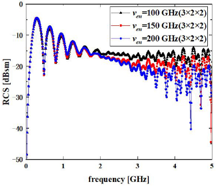
Figure 12: Monostatic RCS of metal sphere coated with time-varying plasma with different collision frequencies .
Figure 12 displays the monostatic RCS under various collision frequencies of plasma. As Fig. 12 indicates, the monostatic RCS decreases with an increase in collision frequency. This is because, as the collision frequency increases, the absorption of EM waves by the plasma sheath is increased, which results in a decrease in the RCS.
Figure 13 shows the monostatic RCS under different thicknesses of plasma sheath. It can be seen that the monostatic RCS decreases with an increase in plasma thickness . The explanation is that as the plasma thickness increases, the incident EM wave needs to traverse through a thicker layer of plasma. This results in more energy being absorbed or scattered away, and leads to a lower RCS of the target.
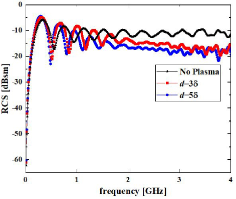
Figure 13: Monostatic RCS of metal sphere coated with time-varying plasma with different thicknesses .
IV. CONCLUSION
In this paper, the MPI-Based Parallel FDTD method and Lorentz transformation are integrated to calculate the EM scattering from a moving metal target coated with time-varying plasma. The accuracy and validity of the parallel Lorentz-FDTD algorithm is verified by comparing its results with those obtained using the serial approach. Moreover, the impacts of time-varying properties, plasma parameters, and motion velocity on the EM scattering properties of a moving and time-varying plasma coated target are investigated. The results reveal that the Parallel FDTD method can enhance the calculating speed and significantly reduce the calculation time when performing EM calculations regarding time-varying and moving dispersive medium targets. Furthermore, as the computational complexity increases, the computational efficiency of the Parallel FDTD algorithm will be further upgraded. Finally, by opting for the appropriate number of processes and an optimal partitioning mode, it is possible to further enhance the computational efficiency and significantly abbreviate the computation time.
ACKNOWLEDGMENT
This work was supported by the National Natural Science Foundation of China (Nos. 62071003, 62201001, 61902252), the Natural Science Foundation of Education Department of Anhui Province, China (Grant No. KJ2020A0024), Anhui Provincial Natural Science Foundation (Nos.2208085QF184), the Open Research Fund of Advanced Laser Technology Laboratory of Anhui Province, China (No. AHL2020KF04), the Open Project of the State Key Laboratory of Millimeter Waves (Grant No. K202222).
REFERENCES
[1] W. Chen, “Research on some key problems of electromagnetic wave propagation and scattering in plasma sheath,” Ph.D. dissertation, Dept. Radio Phys., Xidian Univ., Xian, China, 2018.
[2] L. Kuang, F. Xu, S. Z. Zhu, J. J. Gao, and Z. Q. Zheng, “Relativistic FDTD analysis of far-field scattering of a high-speed moving object,” IEEE Antennas Wireless Propag. Lett., vol. 14, pp. 879-882, Dec. 2014.
[3] G. Z. Niu, Y. M. Liu, B. W. Bai, and D. Yi, “A numerical simulation method of radar echo from a high-speed target,” IEEE Antennas Wireless Propag. Lett., vol. 20, no. 10, pp. 1958-1962, Oct. 2021.
[4] F. Harfoush, A. Taflove, and A. Kriegsmann, “A numerical technique for analyzing electromagnetic wave scattering from moving surfaces in one and two dimensions,” IEEE Trans. Antennas Propag., vol. 37, no. 1, pp. 302-307, 1989.
[5] K. S. Zheng, Z. M. Mu, H. Luo, and G. Wei. “Electromagnetic properties from moving dielectric in high speed with Lorentz-FDTD,” IEEE Antennas Wireless Propag. Lett., vol. 15, pp. 934-937, Sep. 2016.
[6] X. Q. Zhang and Z. P. Nie, “Simulation of electromagnetic scattering from moving perfectly conducting objects based on FDTD,” Chinese J. Radio Science, vol. 24, no. 2, pp. 206-212, Apr.2009.
[7] K.-S. Zheng, J.-Z. Li, G. Wei, and J.-D. Xu, “Analysis of Doppler effect of moving conducting surfaces with Lorentz-FDTD method,” J. Electron. Waves Appl., vol. 27, no. 2, pp. 149-159, Nov.2012.
[8] K. S. Zheng, Y. Li, S. Qin, K. An, and G. Wei, “Analysis of micromotion characteristics from moving conical-shaped targets using the Lorentz-FDTD method,” IEEE Trans. Antennas Propag., vol. 67, no. 11, pp. 7174-7179, Nov.2019.
[9] D. B. Ge and Y. B. Yan, The Finite-Difference Time-Domain Method for Electromagnetic Wave, 3rd ed. Xi’an: Xidian Univ. Press, 2011.
[10] K. Yee, “Numerical solution of initial boundary value problems involving Maxwell’s equations in isotropic media,” IEEE Trans. Antennas Propag., vol. 14, no. 3, pp. 302-307, 1966.
[11] A. Taflove and S. Hagness, Computational Electrodynamics: The Finite-Difference Time-Domain Method, 2nd ed. Boston, MA: Artech House, 2000.
[12] R. C. Bollimuntha, M. F. Hadi, M. J. Piket-May, and A. Z. Elsherbeni, “Near-to-far field transformation in FDTD: A comparative study of different interpolation approaches,” Applied Computational Electromagnetics (ACES) Journal, vol. 36, no. 05, pp. 496-504, 2021.
[13] V. Varadaraian and R. Mittra, “Finite-difference time-domain (FDTD) analysis using distributed computing,” IEEE Microw. Guided Wave Lett., vol. 4, no. 5, pp. 144-145, 1994.
[14] C. Guiffaut and K. Mahdjoubi, “A Parallel FDTD algorithm using the MPI library,” IEEE Antennas Propag. Mag., vol. 43, no. 3, pp. 94-103, 2001.
[15] T. Stefanski and T. D. Drysdale, “Parallel implementation of the ADI-FDTD method,” Micro. Optical Techno. Lett., vol. 51, no. 5, pp. 1298-1304, 2009.
[16] X. Duan, X. Chen, K. Huang, and H. Zhou, “A high performance Parallel FDTD based on Winsock and multi-threading on a PC-Cluster,” Applied Computational Electromagnetics (ACES) Journal, vol. 26, no. 3, pp. 241-249, 2022.
[17] Y.-F. Mao, J.-H. Chen, L. Pan, and X.-M. Wang, “Implementation of two different moving window FDTD methods to simulate the electromagnetic propagation in tunnel with parallel computing,” Applied Computational Electromagnetics (ACES) Journal, vol. 30, no. 04, pp. 428-435, 2021.
[18] J. Chakarothai, K. Wake, and S. Watanabe, “Scalable GPU-parallelized FDTD method for analysis of large-scale electromagnetic dosimetry problems,” Applied Computational Electromagnetics (ACES) Journal, vol. 31, no. 06, pp. 661-668, 2021.
[19] J. Z. Lei, C. H. Liang, W. Ding, and Y. Z, “Study on MPI-based parallel modified conformal FDTD for 3-D electrically large coated targets by using effective parameters,” IEEE Antennas Wireless Propag. Lett., vol. 7, pp. 175-178, Sep. 2008.
[20] D.-B. Ge and L.-X Yang, “FDTD applied to anisotropic medium and its parallel computing,” J. System Engineering Electron., vol. 28, no. 4, pp. 483-485, Apr. 2006.
[21] L.-X. Yang, D.-B. Ge, K. S. Zheng, and B. Wei, “Study of Parallel FDTD algorithm for anisotropic medium on a PC cluster system,” Chinese J. Radio Science, vol. 21, no. 1, pp. 43-48, Feb. 2006.
[22] L.-X Yang, D.-B. Ge, B. Wei, K. S. Zheng, and N. Ge, “A study of FDTD parallel algorithm for anisotropic media with dyadic permittivity and permeability,” Acta Electron. Sinica, vol. 34, no. 9, pp. 1703-1707, Sep. 2006.
[23] X. L. Duan, H. W. Yang, Y. Liu, and L. An, “Auxiliary Differential Equation FDTD method of plasma in parallel environment,” J. Infrared Milli., Terahz Waves, vol. 30, pp. 860-867, 2009.
[24] J. Wang, W. Y. Yin, and Y. S. Xia, “A novel conformal surface current technique for large problems based on high-performance Parallel FDTD method,” IEEE Antennas Wireless Propag. Lett., vol. 12, pp. 11-14, 2013.
[25] Q. W. Shi, B. Zhou, L. M. Zhang, and D. S. Liu, “Hybrid Parallel FDTD calculation method based on MPI for electrically large objects,” Wireless Commun. Mob. Comput., 2019.
[26] L. Man, Y. Bo, H. C. Deng, Z. H. Xiao, and L. X. Yang, “Study on the interaction between relative moving plasma plate and electromagnetic wave,” Chinese J. Radio Science., pp. 1-9, May 2022.
[27] B. Wei, D.-B. Ge, and F. Wang, “A general method for finite difference time domain modeling of wave propagation in frequency-dispersive media,” Acta Phys. Sinica, vol. 57, no. 10, Oct. 2008.
BIOGRAPHIES

Hai-Yan Li was born in Huaibei City, Anhui Province, China, in 1999. She received the B.S. degree in electronic information engineering from Huainan Normal University, Huainan, China, in 2021. She is currently working toward the master’s degree in electromagnetic field and microwave technology of Electronic Information with the School of Electronic Information Engineering, Anhui University, Hefei, China. Her current research interest is computational electromagnetism.

Xian-Min Guo was born in Xian-yang City, Shanxi Province, China, in 1999. She received the B.S. degree in electronic information engineering from Shandong University of Technology, Zibo, China, in 2021. She is currently working toward the master’s degree in electromagnetic field and microwave technology of Electronic Information with the School of Electronic Information Engineering, Anhui University, Hefei, China. Her current research interest is computational electromagnetism and plasma physics.

Yong Bo was born in Shandong Province, China, on November 11, 1989. He received the B.S. degree in Shandong University of Science and Technology, Qingdao, China, in 2012, and the Ph.D. degree from the Center for Information Geoscience, University of Electronic Science and Technology of China, Chengdu, China. He is currently a Lecturer with the University of Anhui, Hefei, China. The main subjects of his interest include computational electromagnetic, wave propagation in plasmas, and low temperature plasma technology and application.

Wei Chen was born in Jiangsu Province, China, in 1987. He received the B.S. and M.S. degrees from Jiangsu University, Jiangsu, China, in 2010 and 2013, respectively, and the Ph.D. degree from Xidian University, Xi’an, China, in 2018. He is currently a Lecturer with the School of Electronics and Information Engineering, Anhui University, Hefei, China. His current research interests include numerical methods in electromagnetic scattering from plasma and wave propagation in complex systems.

Li-Xia Yang was born in Ezhou, Hubei, China, in 1975. He received the B.S. degree in physics from Hubei University, Wuhan, China, in 1997, and the Ph.D. degree in radio physics from Xidian University, Xi’an, China, in 2007. Since 2010, he has been an Associate Professor with the Communication Engineering Department, Jiangsu University, Zhenjiang, China. From 2010 to 2011, he was a Postdoctoral Research Fellow with the Electro Science Laboratory (ESL), The Ohio State University, Columbus, OH, USA. From 2015 to 2016, he was a Visiting Scholar with the Institute of Space Science, The University of Texas at Dallas, Dallas, TX, USA. From 2016 to 2019, he has been a Professor, a Ph.D. Supervisor, and the Chairman of the Communication Engineering Department, Jiangsu University. Since 2020, he has been a Distinguished Professor, a Ph.D. Supervisor, and the Vice Dean with the School of Electronic and Information Engineering, Anhui University, Hefei, China. His research interests include wireless communication technique, radio sciences, the computational electromagnetic, and the antenna theory and design in wireless communication systems. He is a member of the Editor Board of Radio Science Journal in China.

Zhi-Xiang Huang was born in Anhui, China, in 1979. He received the B.S. and Ph.D. degrees from Anhui University, Hefei, China, in 2002 and 2007, respectively. He was a Visiting Scholar with Iowa State University, USA, from September 2010 to September 2011. From August 2013 to October 2013, he was a Visiting Professor with The University of Hong Kong. From February 2014 to February 2015, he was a Visiting Professor with the Beijing National Laboratory for Condensed Matter Physics, Institute of Physics, Chinese Academy of Sciences. He has published one monograph on the symplectic finite-difference time-domain method and two book chapters at CRC Press and In Tech Publishers. He has published 60 peer-reviewed journal articles included in the Web of Science Core Collection. His current research interests include time-domain numerical methods, metamaterials, and active metamaterials. He is a member of the OSA. In 2015, he was awarded the Second Prize of Science and Technology from the Anhui Province Government, China, and the National Science Foundation for Outstanding Young Scholar of China, in 2017.

Jia-Chen Wangwas born in Hefei City, Anhui Province, China, in 2003. He is currently working toward the B.S. degree in communication engineering with the School of Electronic Information Engineering, Anhui University, Hefei, China. His current research interest is microwave radar.

Xin-Jie Duan was born in Luan City, Anhui Province, China, on April 23rd, 2005. She is currently an undergraduate student majoring in Communication Engineering at the School of Electronic Information Engineering, Anhui University, Hefei, China. She was awarded the annual study scholarship. Her current research interest is computational electromagnetism.
ACES JOURNAL, Vol. 40, No. 2, 112–122
doi: 10.13052/2025.ACES.J.400204
© 2025 River Publishers