Parameter Sensitivity Analysis of 3D-Printed W-Band Reflective Fresnel Lens Antenna based on Acrylonitrile Butadiene Styrene Plastic
Shunichi Futatsumori
Surveillance and Communications Department, Electronic Navigation Research Institute
National Institute of Maritime, Port and Aviation Technology, Chofu, Tokyo 182–0012, Japan
futatsumori@mpat.go.jp
Submitted On: July 30, 2023; Accepted On: May 3, 2024
ABSTRACT
To improve the design of the 3D-printed W-band reflective Fresnel lens antenna based on acrylonitrile butadiene styrene (ABS) plastic, we have examined the parameter sensitivity related to the dielectric material constant. Although we have developed a high-gain millimeter-wave reflective Fresnel lens antenna, the material constant of the ABS filament used in 3D printing needs further investigation to optimize antenna performance. First, a 150-mm-diameter W-band reflector Fresnel antenna is designed and analyzed using finite-difference time-domain (FDTD) analysis. The analyzed and measured maximum antenna gains are 33.3 and 32.4 dBi, respectively. Subsequent sensitivity analysis focused on the impact of the loss tangent, relative dielectric constant, and folding length of the lens, based on both FDTD analysis and measurements.
Index Terms: 3D printer, acrylonitrile butadiene styrene plastic, finite-difference time-domain method, reflective Fresnel lens antenna, relative dielectric constant.
I. INTRODUCTION
The fabrication of antennas using 3D printers holds promise for delivering high-performance antennas at reduced costs [1]–[7]. In the context of millimeter-wave radar applications for civilian use, our team has explored radars for uses such as helicopter obstacle detection and airport runway foreign object debris detection system [8]–[12]. For instance, helicopter flight tests are conducted to assess the detection efficacy for high-voltage power lines and their supporting pylons [10]. The radar systems in development utilize a parabolic reflector antenna made of carbon fiber reinforced plastics (CFRP). The CFPR reflector antenna, of size 130 mm height and 130 mm width, has measured antenna gain of 33 dBi gain at 76.5 GHz [13]. By comparing the aperture size and the gain of the proposed 3D printed antenna, they have close
characteristics. However, the fabrication cost of the CFPR reflector is much higher than that of a reflector antenna using a 3D printer. The dielectric antennas created with 3D printers, particularly those using acrylonitrile butadiene styrene (ABS) plastic filaments, present certain advantages over the CFRP reflector antenna. Yet, the ABS filaments tend to exhibit pronounced dielectric loss characteristics in the millimeter-wave region. The loss tangent is a parameter that represents the loss of electrical energy in a dielectric material. The dielectric loss is usually caused by the thermal energy generated when an alternating electric field is applied to a dielectric material. When a dielectric material with a high loss tangent is employed as a lens material, the dielectric loss will be large and the maximum gain will be reduced. To address this, a reflective Fresnel lens antenna with an antenna gain exceeding 30 dBi was introduced for millimeter-wave radars [4][5]. Figure 1 illustrates the structure of both the reflector lens and the reflective Fresnel lens antennas.
In this paper, our objective is to refine the design of the 3D-printed reflective Fresnel lens antenna. We conducted a parameter sensitivity analysis concerning the dielectric material constant using the finite-difference time-domain (FDTD) technique. Such an analysis is pivotal for understanding the effects of dielectric material constants and physical dimensions in order to design high-performance lens antennas.
First, we discuss the design and the FDTD analysis results of the W-band reflective Fresnel lens antenna developed up to this point. Subsequently, we compare the analyzed, and fabricated antenna characteristics. We then explore the antenna parameter dependencies on the dielectric loss tangent and relative permittivity of the lens, based on the FDTD analysis. Discussions on the effects stemming from the dielectric loss tangent values are presented. In conclusion, we investigate how maximum gain is influenced by the dielectric constant and the focal length through numerical analysis.
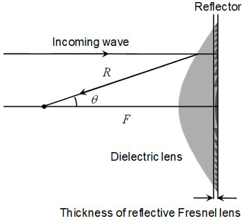
Figure 1: Structure of the reflector lens antenna and reflective Fresnel lens antenna.
II. 150 mm-DIAMETER W-BAND REFLECTIVE FRESNEL LENS ANTENNA
For the parameter sensitivity analysis, we utilize the previously designed 150-mm-diameter W-band reflector Fresnel antenna as a typical example [5]. Figure 1 depicts the structures of both the reflector lens antenna and the reflective Fresnel lens antenna. The lens curve for the conventional reflector lens antenna is defined by [14]:
| (1) |
where n and R are the index of refraction and the distance between any point on the lens surface and the focal point, respectively. Furthermore, is the ray angle and F is the focal length. An integral number of wavelengths inside the dielectric lens is then subtracted from the lens curve described in equation (1) to define the Fresnel lens.
Table 1: Design and FDTD analysis parameters of the reflective Fresnel lens antenna
| Frequency (GHz) | 76.5 |
| Focal length (mm) | 75 |
| Dimensions (diameter in mm) |
150 |
| Folding length (mm) | 3.7 |
| Thickness (mm) | 4.3 |
| Relative permittivity of lens material | 2.3 |
| Loss tangent of lens material | 310 |
| Cell dimensions | 518525523 |
| X-axis cell size (mm) | 0.309 (Min.), 0.465 (Max.) |
| Y-axis cell size (mm) | 0.100 (Min.), 0.466 (Max.) |
| Z-axis cell size (mm) | 0.165 (Min.), 0.274 (Max.) |
| Time increment (s) | 2.710 |
| Material of bottom of lens | Perfect electric conductor |
| Primary source | WR-10 open-ended waveguide |
| Specification of computer used for analysis | CPU: Intel Core i7–9800X Main memory: 128 GB GPU: Nvidia Tesla K40c |
| Analysis time | 16 minutes |
Table 1 lists the design and FDTD analysis parameters. The design frequency is 76.5 GHz, which aligns with the central frequency of the low-transmitting power millimeter-wave radar system, while the focal length F is 75 mm. Moreover, the diameter of the reflector lens measures 150 mm. We assumed a relative permittivity of 2.3, based on the fabrication with ABS plastic filament, and tan is 310. Since the accurate permittivity and permittivity required to design the lens were unknown at the design stage, we used the values of typical ABS resins as a result of a literature review. Therefore, the dielectric constant 2.3 and the dielectric loss tangent 310 are the starting points used for analysis. With the Fresnel structure, the thickness of the reflective Fresnel lens is narrowed down to 4.3 mm, marking a 17.8% reduction from the 24.1 mm seen in conventional lens structures. Figure 2 showcases the analyzed model of the designed reflective Fresnel lens antenna with a diameter of 150 mm. The zx-plane in Fig. 2 is defined as the azimuth direction, and the yz-plane is defined as the elevation direction. The default value of the folding length is 3.7 mm. The thickness of the lens stands for the sum of the folding length and the basement thickness. The basement thickness is fixed at 0.5 mm throughout the analysis in this paper. A perfect electric conductor is positioned behind the dielectric lens, and the primary source is the WR-10 open-ended waveguide. The antenna’s excitation polarization follows a vertical polarization.
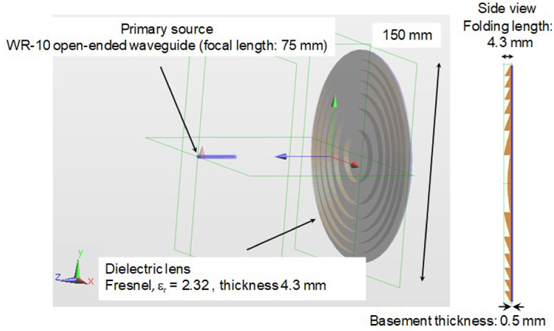
Figure 2: 150-mm-diameter reflective Fresnel lens antenna analysis model.
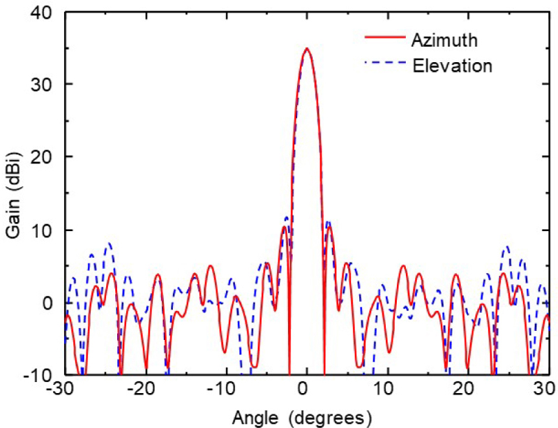
Figure 3: Analyzed azimuth and elevation radiation patterns at 76.5 GHz.
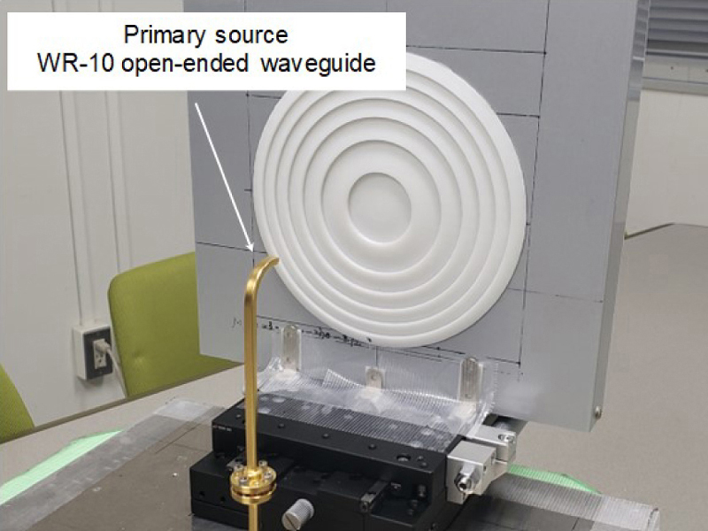
Figure 4: Overview of the fabricated reflective Fresnel lens antenna using a 3D printer.
The reflective Fresnel lens antenna is analyzed using the commercially available FDTD software SEMCAD X from Schmid & Partner Engineering AG in Zürich, Switzerland [15]. As shown in the Table 1, the cell dimension is 518525523. In addition, the nonuniform mesh is applied for the FDTD voxels. The minimum and maximum cell size are shown in Table 1.
The time increment is 2.710 seconds. Based on the nonuniform mesh, the lens surface has a staircase structure in the analysis. The computer with Intel Core i7–9800X CPU, 128 GB main memory and Nvidia Tesla K40c GPU is used for the analysis. The analysis time is approximately 16 minutes.
Figure 3 presents the analyzed azimuth and elevation radiation patterns at 76.5 GHz. The antenna achieves a maximum gain of 33.3 dBi, with azimuth and elevation half power beamwidth (HPBW) of 1.7 degrees and 1.6 degrees, respectively. Subsequently, the reflective Fresnel lens antenna is manufactured using the Afinia H800 3D Printer from Afinia 3D, Chanhassen, MN. The 3D printer produced laminations in 0.1 mm increments. Figure 4 offers a detailed view of the fabricated reflective Fresnel lens antenna. To serve as a reflective surface, a 0.1 mm thick aluminum tape was affixed to the back of the lens. Moreover, the WR-10 open-ended waveguide is positioned at the focal point, consistent with the FDTD analysis. To enable adjustments to the focal length during measurements, the Fresnel lens is mounted on a stage equipped with a micrometer.
Figure 5 compares the analyzed (focal length: 75 mm) and measured (focal length: 79 mm) azimuth radiation patterns at 76.5 GHz. The antenna achieved a maximum gain of 32.4 dBi with a focal length of 79 mm, while its designed focal length is 75 mm. Comparing the analyzed and measured maximum antenna gains reveals a discrepancy of less than 1 dB in gain, but a focal point difference of approximately 5 mm. In contrast, the analyzed, and measured HPBW are 1.1 degrees and 1.0 degrees, respectively. Although the analysis measured results largely align, a parameter sensitivity analysis will be conducted for further refinement.
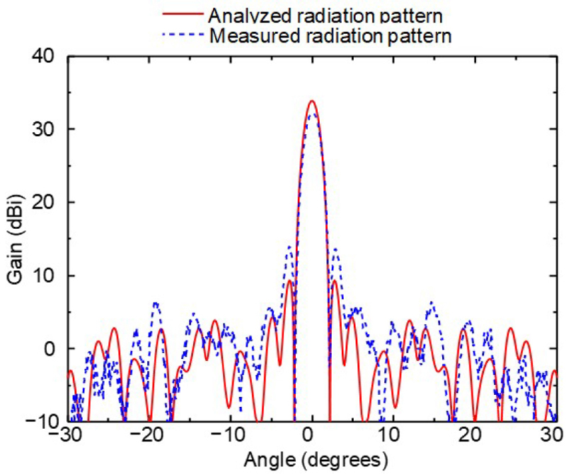
Figure 5: Analyzed (focal length: 75 mm) and measured (focal length: 79 mm) azimuth radiation patterns at 76.5 GHz.
III. PARAMETER SENSITIVITY ANALYSIS
The parameter sensitivity of the 3D-printed reflective Fresnel lens antenna has been analyzed using the FDTD method. The relationship between the maximum antenna gains and the loss tangent of the dielectric lens is explored by varying the loss tangent between 0 and 5 10, while keeping other analysis parameters consistent with those in Table 1. Figure 6 illustrates the maximum antenna gains at 76.5 GHz relative to the loss tangent. An increase in the loss tangent leads to a reduction in antenna gain; for instance, antenna gains of 33.3 dBi and 32.8 dBi are observed for loss tangent values of 310 and 410, respectively. Compared to the measured antenna gain of 32.4 dBi, a loss tangent value of around 410 aligns closely with the measured results.
Subsequently, the maximum antenna gains in relation to the relative permittivity were assessed. Figure 7 displays the analyzed maximum antenna gain at 76.5 GHz for various relative permittivity values, which range between 1.5 and 3. Additionally, the focal lengths considered are 70 mm, 75 mm, and 80 mm. The changes in maximum gain in response to relative permittivity variations are mild. Specifically, the gain difference when altering the relative permittivity between 2 and 3 registers at approximately 1.4 dB for a focal distance of 75 mm.
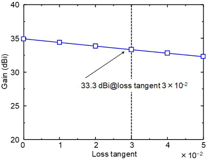
Figure 6: Analyzed maximum antenna gains for the reflective Fresnel lens antenna at 76.5 GHz, plotted against loss tangent.
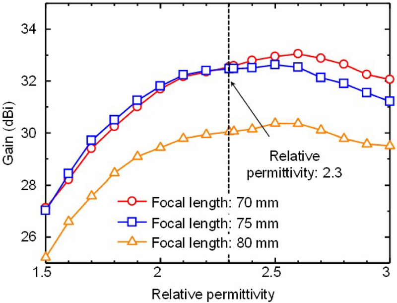
Figure 7: Analyzed maximum antenna gains of the reflective Fresnel lens antenna at 76.5 GHz, analyzed with respect to relative permittivity.
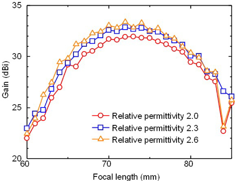
Figure 8: Analyzed maximum antenna gains for the reflective Fresnel lens antenna at 76.5 GHz, plotted against focal length.
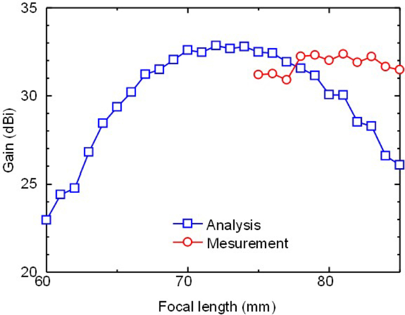
Figure 9: Analyzed and measured maximum antenna gains for the reflective Fresnel lens antenna at 76.5 GHz, with a fixed focal length of 75 mm.
Moreover, the effects of varying focal lengths on maximum antenna gains are evaluated. Figure 8 presents the analyzed maximum gains at 76.5 GHz for focal lengths spanning between 60 mm and 85 mm. The relative permittivity values considered are 2.0, 2.3, and 2.6. The graph demonstrates that the variation in gain in response to changes in focal length remains reasonably uniform. When the dielectric constant is 2.3, the maximum gain difference is about 3.5 dB upon shifting the dielectric constant from 65 mm to 80 mm. For dielectric constants 2.0 and 2.6, a rapid maximum gain decrease is observed at a focal length of 84 mm. This phenomenon occurs due to the drop of the main lobe due to the dielectric lens not being formed due to off-focus region.
Figure 9 compares the maximum gains at 76.5 GHz for focal lengths ranging from 60 mm to 85 mm, with a fixed relative permittivity of 2.3. Analytical results depict a gain exceeding 30 dBi for focal lengths between 66 mm and 80 mm. In contrast, measured data indicates gains surpassing 30 dBi for focal lengths between 75 mm and 85 mm. Figures 9 and 10 shows the maximum gain frequency characteristics and the maximum gain focal length characteristic, respectively. From these results, it is confirmed the focal length between the analysis and the measurement differs by between 5 mmand 10 mm.
Next, the frequency characteristics of the reflective Fresnel lens antenna are probed. Figure 10 shows the analyzed and measured maximum antenna gains against frequency, considering focal lengths of 70 mm, 75 mm, and 80 mm. For reference, the frequency characteristics of a convex lens of the same diameter are included. Unlike the convex lens, which lacks peaks in its frequency band, the reflective Fresnel lens antenna displays a peak frequency contingent on its focal length. The distinct frequency-dependent gain traits are attributed to the Fresnel lens structure. Furthermore, the measured frequency attributes, recorded with a 79 mm focal length, are depicted as black dots. In this scenario, the measured outcomes harmonize well with the analysis for a 70 mm focal length.
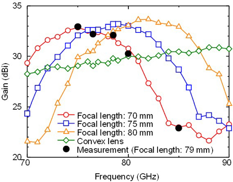
Figure 10: Analyzed and measured maximum antenna gains of the reflective Fresnel lens antenna across different focal lengths.
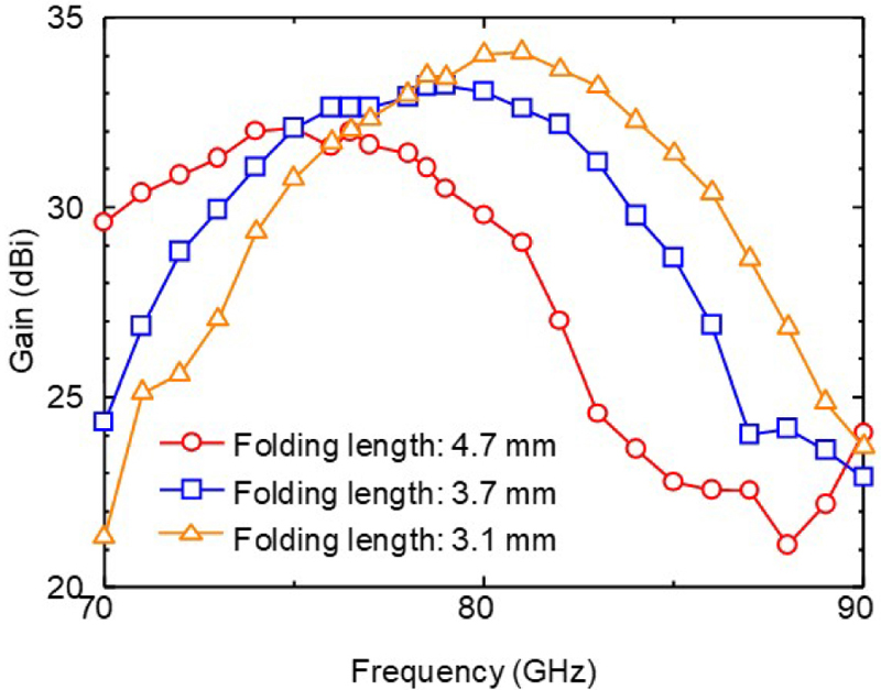
Figure 11: Analyzed (focal length: 75 mm) antenna gain frequency characteristics of the reflective Fresnel lens antenna with different folding length.
Lastly, we examined how antenna gain characteristics are influenced by the folding length, which represents the thickness of the Fresnel lens. Figure 11 presents the analyzed frequency characteristics of the reflective Fresnel lens antenna for various folding lengths, with the focal length consistently set at 75 mm. The designed and fabricated folding length is 3.7 mm, but for the analysis, this length is also adjusted to 4.7 mm, 3.7 mm, and 3.1 mm. It is important to note that the true thickness of the lens equals the sum of the folding length and the basement thickness. The basement thickness in this design is 0.5 mm. Adjusting the folding length causes the maximum gain frequency to shift, ranging between shifts of 5 GHz/mm and 10 GHz/mm. These results underscore the significant impact that the thickness of the folds, due to the Fresnel structure, has on frequency characteristics. Note that the antenna gain is dropped at 86 GHz and higher frequencies for folding length 3.1 mm. This is mainly due to the main lobe is not formed by the dielectric lens due to the off-focusing.
IV. CONCLUSION
The parameter sensitivity of the 3D printed reflective Fresnel lens antenna was scrutinized using the FDTD method. Differences between the analyzed and measured results were explored. Subsequent FDTD analyses were conducted to understand the effects of lens material constants on antenna characteristics. The observed loss tangent value of around 410 aligns closely with measured results. Moreover, the antenna characteristics’ dependency on the relative permittivity is relatively moderate. However, the folding length of the reflective Fresnel lens significantly influences frequency characteristics. Insights from these studies will guide future antenna designs aiming for highergains.
ACKNOWLEDGMENT
This work was partly supported by JSPS KAKENHI Grant Number 20K04931.
REFERENCES
[1] P. Nayeri, M. Liang, R. A. Sabory-García, M. Tuo, F. Yang, M. Gehm, H. Xin, and A. Z. Elsherbeni, “3D printed dielectric reflectarrays: Low-cost high-gain antennas at sub-millimeter waves,” IEEE Transactions on Antennas and Propagation, vol. 62, no. 4, pp. 2000–2008, Apr. 2014.
[2] K. Mazouni, J. Lanteri, N. Yonemoto, J. Y. Dauvignac, C. Pichot, and C. Migliaccio, “78.5GHz Fresnel reflector with circular polarization for collision avoidance radar on rescue helicopters,” in Proceedings of the 3rd European Conference on Antennas and Propagation, Berlin, pp. 1819–1823,2009.
[3] S. Futatsumori, A. Kohmura, and N. Yonemoto, “Performance measurement of compact and high-range resolution 76 GHz millimeter-wave radar system for autonomous unmanned helicopters,” IEICE Transactions on Electronics, vol. E96.C, no. 4, pp. 586–594, Apr. 2013.
[4] S. Futatsumori, K. Morioka, A. Kohmura, N. Sakamoto, T. Soga, and N. Yonemoto, “Feasibility evaluations of three-dimensional-printed high-gain reflectarray antenna for W-Band applications,” IEICE Communications Express, vol. 7, no. 6, pp. 230–235, 2018.
[5] S. Futatsumori, N. Sakamoto, and T. Soga, “Three-dimensional-printed W-band high-gain reflector Fresnel lens antenna based on acrylonitrile butadiene styrene plastic,” IEICE Communications Express, vol. 8, no. 7, pp. 275–280, 2019.
[6] S. Futatsumori, “Dielectric material constant sensitivity analysis of 3D-printed W-band reflector Fresnel lens antenna based on acrylonitrile butadiene styrene,” Proceedings of 2023 International Applied Computational Electromagnetics Society, pp. 1–2, Mar. 2023.
[7] A. Belen and E. Tetik, “Realization of modified elliptical shaped dielectric lens antenna for X band applications with 3D printing technology,” ACES Journal, vol. 35, no. 8, pp. 916–921, Aug. 2020.
[8] S. Futatsumori, K. Morioka, A. Kohmura, M. Shioji, and N. Yonemoto, “Evaluation of polarization characteristics of power-line RCS at 76 GHz for helicopter obstacle detection,” Electronics Letters, vol. 51, no. 14, pp. 1110–1111, July 2015.
[9] S. Futatsumori, K. Morioka, A. Kohmura, K. Okada, and N. Yonemoto, “Design and field feasibility evaluation of distributed-type 96 GHz FMCW millimeter-wave radar based on radio-over-fiber and optical frequency multiplier,” Journal of Lightwave Technology, vol. 34, no. 20, pp. 4835–4843, Oct. 2016.
[10] S. Futatsumori, C. Amielh, N. Miyazaki, K. Kobayashi, and N. Katsura, “Helicopter flight evaluations of high-voltage power lines detection based on 76 GHz circular polarized millimeter-wave radar system,” in Proceedings of the 15th European Radar Conference, pp. 218–221, 2018.
[11] S. Futatsumori, N. Yonemoto, N. Shibagaki, Y. Sato, and K. Kashima, “Detection probability estimation of 96 GHz millimeter-wave airport foreign object debris detection radar using measured radar cross section characteristics,” in Proceedings of the 15th European Conference on Antenna and Propagation, pp. 1–4, Mar. 2021.
[12] S. Futatsumori, N. Yonemoto, N. Shibagaki, Y. Sato, and K. Kashima, “Performance evaluations of airport runway foreign object detection system using a 96 GHz millimeter-wave radar system based on international standard,” in Proceedings of the 47th International Conference on Infrared, Millimeter, and Terahertz Waves (IRMMW-THz2022), pp. 1–2, 2022.
[13] S. Futatsumori, A. Kohmura, and N. Yonemoto, “Development of compact and high performance 76GHz millimeter-wave radar system for autonomous unmanned helicopters,” Institute of Electronics, Information and Communication Engineers (IEICE) Technical Report, vol. 110, no. 160, pp. 7–11, July 2010.
[14] J. Kraus, “Some unique reflector-type antennas,” IEEE Antennas and Propagation Society Newsletter, vol. 24, no. 2, pp. 9–12, Apr. 1982.
[15] SEMDAD X User Manual, Schmid & Partner Engineering AG, Zurich, 2010.
BIOGRAPHIES

Shunichi Futatsumori received the B.E., M.E., and Ph.D. degrees in Electronics and Information Engineering from Hokkaido University, Sapporo, Japan, in 2004, 2006, and 2009, respectively. Between 2008 and 2009, he held the position of Research Fellow with the Japan Society for the Promotion of Science. In 2009, he joined the Electronic Navigation Research Institute (ENRI) in Japan, where his research focused on millimeter-wave radar systems and electromagnetic compatibility issues. He currently serves as a principal researcher at ENRI. In 2009, Dr. Futatsumori was honored with the Young Researcher’s Award from IEICE and the APMC prize. He is a member of both IEEE and IEICE.
ACES JOURNAL, Vol. 39, No. 3, 231–236
doi: 10.13052/2024.ACES.J.390308
© 2024 River Publishers