Impact Evaluation of an External Point Source to a Generalized Model of the Human Neck
Anna A. Varvari, Dimitrios I. Karatzidis, Tadao Ohtani, Yasushi Kanai, and Nikolaos V. Kantartzis
1Department of Electrical and Computer Engineering
Aristotle University of Thessaloniki, 54124, Greece
avarvari, karatzidis, kant@ece.auth.gr
2Independent Researcher
Asahikawa, 070–0841, Japan
bytcg100@ybb.ne.jp
3Department of Niigata Institute of Technology
Kashiwazaki, 945–1195, Japan
kanai@iee.niit.ac.jp
Submitted On: July 30, 2023; Accepted On: November 20, 2023
ABSTRACT
A methodical approach for assessing the effects of an external point source to a non-spherical model of the human neck is presented in this paper. The neck model consists of multilayered spheres to represent the skin, fat, muscle tissues, thyroid, and esophagus. The novel geometry enables the formulation of dyadic Green’s functions to accurately calculate the electric fields, considering the suitable surface boundary conditions and the superposition principle. Numerical outcomes for a Hertz dipole (i.e., a wireless network antenna) at the frequency of 2.4 GHz certify the benefits of the technique and elaborately describe the responsiveness of the neck/thyroid to the selected source.
Index Terms: biomedical engineering, computational electromagnetics, Green’s function methods, wireless body area networks.
I. INTRODUCTION
The rapid evolution of healthcare wireless body area networks (WBANs) reflects the escalating need for real-time smart infrastructures to reliably monitor key gauges of the human body [1, 2]. To this aim, an impressive variety of such systems has been developed in terms of specialized antennas [3–5] and advanced biomedical applications [6, 7]. On the other hand, the assessment of electromagnetic radiation effects of several WBANs upon the human body and particularly on the thyroid has lately become a critical problem [8, 9]. Existing studies concerning the radiofrequency spectrum focus mainly on thermal analysis [10, 11]. However, there is an ever-increasing demand for simplified, precise, and economical models of the human neck to further explore the thyroid sensitivity to electromagnetic radiation.
This paper presents a systematic technique for the rigorous calculation of electromagnetic fields involving body area networks near the human neck. The proposed model represents abstractly the neck tissues as spherical layers and structures, permitting the parametric study of the thyroid. Concerning the mathematical formulation and the numerical results, the rapid and accurate derivation of the latter is enabled with the introduction of a new set of dyadic Green’s functions (dGfs). In this framework, we define the geometry of the model representing each part of the neck with a spherical body. Then, the electric field is determined using the proposed dGf-based technique. Finally, the results, so derived, are compared and validated through numerical outcomes obtained from a well-known computational package.
II. GEOMETRY OF THE NECK MODEL
The featured model, presented in Fig. 1, consists of the host sphere that has two spherical layers for the representation of the skin and the fat , while a third cocentric inclusion depicts the muscle tissue . Also, the non-overlapping spherical eccentric inclusions for the right thyroid lobe , the left thyroid lobe , the trachea , the esophagus and the other neck tissues render the model non-spherical since the model lacks spherical symmetry. Each inclusion has an outer radius and a thickness , for , with the cocentric ones centered at origin and the eccentric ones at , defined by vectors , for . Note that all parts are occupied by a lossy dielectric medium characterized by a complex relative permittivity and a wavenumber , for and the angular frequency. Lastly, in our analysis, the free-space wavenumber is , regarding a typical time dependence and the coordinate system or , for , defined at the origin or , respectively.
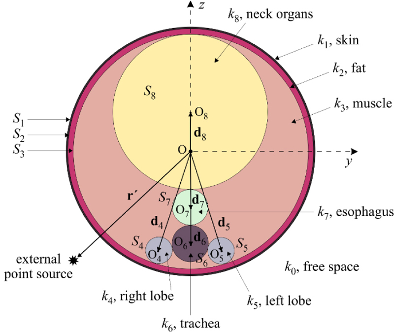
Figure 1: Cross-section of the generalized neck model.
III. MATHEMATICAL FORMULATION
Let us assume that is the free-space electric-field dGf which provides the electric field of an external point source . In this case, the free-space electric-field dGf, , manifests as the solution of the dyadic Helmholtz equation , where stands for the unit dyad. By implementing the Ohm-Rayleigh method, discussed in [12], we can derive
| (1) |
where and are the corresponding unit vectors, (for ) and . It is stressed that in (3), according to the theoretical formulation of Green’s functions, indicates the respective vector spherical harmonic or N. Therefore, for , it holds that
| (2) |
| (3) |
with being a spherical Bessel function of the first kind (when ) or a Hankel function (when ) and a Legendre function of the first kind [13, 14]. Observe that (3) holds solely for , otherwise the superscripts of F must be reversed.
Regarding the proposed neck model, the desired dGf exhibits a bilocal spatial dependence, as the position vector of its various parts and the source are r and . Moreover, the latter are likely to not belong to the same coordinate system and/or may not end at the same surface. Consequently, and in terms of [15], we denote as the location of the field point of interest, considering that it lies in the region limited by two surfaces, namely and . Therefore, the electric dGf at is acquired through , with and the respective electric dGfs at the and of the region where is located. As a result, the electric-field intensity at is derived as
| (4) |
for V the volume confined between surfaces and and the electric current density of the external source at . In this context, the necessary dGfs at every point of interest, confined between surfaces and (for ), as well as those in the free space, are
| (5) |
| (6) |
| (7) |
| (8) |
| (9) |
| (10) |
| (11) |
| (12) |
| (13) |
Using the free-space dyad, the above system becomes
| (14) |
| (15) |
| (16) |
| (17) |
| (18) |
| (19) |
| (20) |
| (21) |
| (22) |
where and are the unknown wave amplitudes. Following the technique described in [13, 16], we then solve the system of (14)-(22) and obtain the required wave amplitudes, which, in turn, allows us to calculate the electric field given by (5).
IV. NUMERICAL VERIFICATION
The computation of the electric-field intensity (EFI) at the (namely, at the neck middle cross-section) plane is deemed an essential step for the validation of the new technique. Thus, for a regular male neck model, as the one in Fig. 1, the average dimensions and the dielectric media properties of its various parts, at the frequency of GHz, are given in Table 1. Actually, this structure is fairly challenging owing to the different complex relative permittivities and hence the abruptly varying spherical media interfaces. Also, in (14)-(22), the number of terms, , needed for the convergence of the infinite sums is up to the order of tens, depending on the type of the field. In particular, for the incident field, the value of can be several times larger (-) than the value for the scattered field (-), since the former is evaluated near the point source where field fluctuations are more abrupt. The main setup involves a Hertz dipole (in the sense of a wireless network antenna) with a parallel (along the -axis) and a perpendicular (along the -axis) polarization relative to the neck surface. For our comparisons, the exact same model has been numerically simulated by the CST Microwave Studio [17]. This package employs the finite integration technique and the finite-difference time-domain method in a domain discretized into adaptive hexahedral cells.
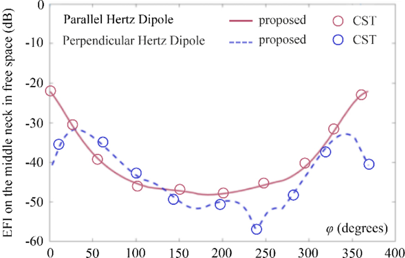
Figure 2: Magnitude of the electric-field intensity, , at the plane without the neck vs angle at . The Hertz dipole is placed on the -axis (, , and ) and the reference level is set at , , and .
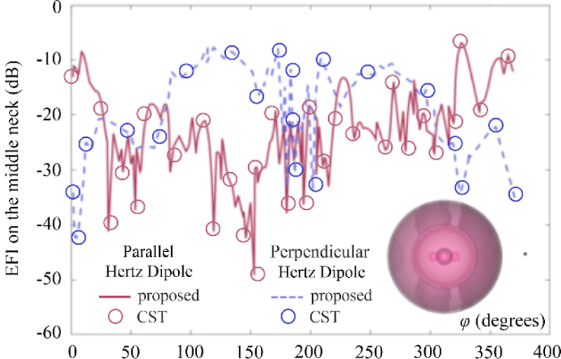
Figure 3: Magnitude of the electric-field intensity, , at the neck middle cross-section () plane vs angle at for the Hertz dipole and the reference level of Fig. 2 [Inlet figure: Electric-field intensity map at the plane, generated by an -oriented electric Hertz dipole (marked as a dot on the right-hand side), with each shade of grey spanning at a level of 3 dB].
A. Electric field calculation
Based on the above aspects, Figs. 2 and 3 illustrate the EFI magnitude at ( plane) for a Hertz dipole (placed on the -axis: , , ) at GHz, in the absence and presence of the featured neck model, respectively. As promptly detected, the accuracy of our technique is promising, since in both scenarios the retrieved results are certainly in very good agreement with those of the computational package. This deduction is deemed even more important, considering the complicated geometry of the entire neck model, the multitude of materials, and the two different dipole polarizations. In fact, recalling the complex relative permittivities of Table 1, one can comprehend that the generalized dGf-based method is capable of successfully treating strongly dissimilar media (even when rather different imaginary parts are involved). Concerning the consistency of our scheme, the inlet figure of Fig. 3 shows the EFI map at the plane for a -oriented Hertz dipole. Observe the smoothness of the plot along with the absence of any nonphysical numerical artifacts due to scattered waves in the vicinity of the source and at the different media interfaces.
Table 1: Average dimensions and material properties for the different parts of the proposed male neck model
| Neck Model Part |
Outer Radius (mm) |
Thickness/Distance (mm) |
Complex rel Permittivity |
|---|---|---|---|
| Skin | |||
| Fat | |||
| Muscle | |||
| Right lobe | |||
| Left lobe | |||
| Trachea | |||
| Esophagus | |||
| Organs of the neck |
Moreover, Fig. 4 presents the EFI magnitude along the perimeter of the neck middle cross-section at ( plane), owing to its critical significance at such studies. Note the promising agreement of the results with those of the computational package, despite the demanding configuration of the problem. On the other hand, these outcomes reveal a strong dependence of the EFI magnitude from the polarization of the Hertz dipole. Specifically, the EFI magnitude of the parallel dipole is larger than that of its perpendicular counterpart, for certain values of angle . Finally, it should be mentioned that the proposed algorithm is very fast, owing to the straightforward implementation of the dGfs.
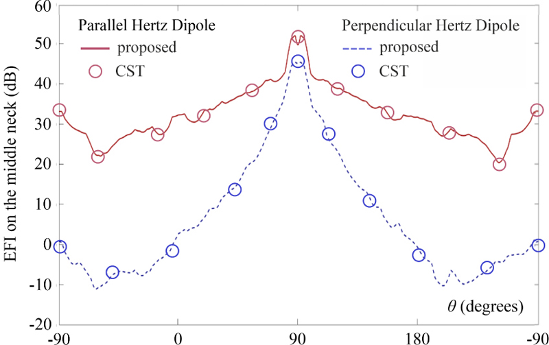
Figure 4: Magnitude of the electric-field intensity, , at the neck middle cross-section () plane vs angle at for the Hertz dipole and reference level at , , and .
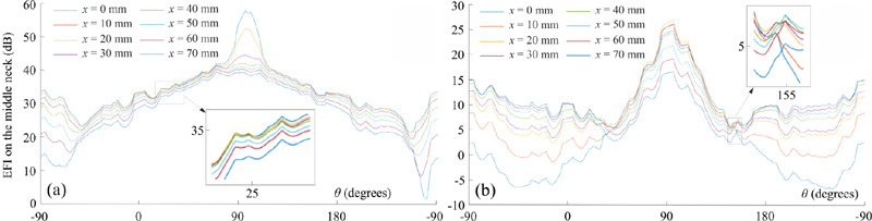
Figure 5: Magnitude of the electric-field intensity, , at the neck middle cross-section () plane vs angle for different polarizations of the Hertz dipole, when , , and . (a) Parallel to -axis and (b) parallel to -axis. Angle is measured clockwise from the -axis on the plane, while the inlet figures are magnified plots of the results in the dotted areas.
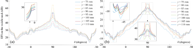
Figure 6: Magnitude of the electric-field intensity, , at the neck middle cross-section () plane vs angle for different polarizations of the Hertz dipole, when , , and . (a) Parallel to -axis and (b) parallel to -axis. Angle is measured clockwise from the -axis on the plane, while the inlet figures are magnified plots of the results in the dotted areas.
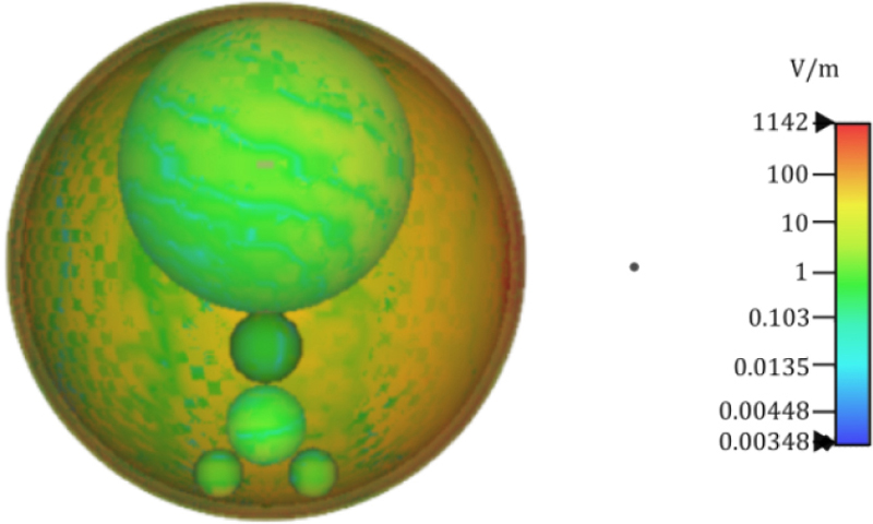
Figure 7: Electric-field intensity map at a cross-section of the proposed neck model in Fig. 1. The source is represented as a dot on the right-hand side.
B. Parameterization of the source location
Having validated the accuracy and efficiency of the featured technique, we, now, concentrate on the impact of the Hertz dipole source on the new neck model. To this objective, we compute the electric-field intensity around the neck middle cross-section ( plane) for various locations and polarizations of the Hertzdipole.
In this framework, Fig. 5 depicts the EFI magnitude around the neck middle cross-section in the case of a Hertz dipole parallel to -axis and -axis, respectively. The source moves along the -axis; in particular , with its other coordinates fixed at and . It should be stressed that since in our numerical simulations, the Hertz dipole is not considered as a point source, its coordinates are measured from the edge that it is closest to the neck model. Consequently, the EFI magnitude around the neck middle cross-section increases as the point source approaches the model and decreases when it departs. Moreover, the shape of the curves in Fig. 5 (and magnified regions) is not seriously affected since the dipole moves along the -axis.
Conversely, Fig. 6 examines the scenario of a Hertz dipole (for both polarizations) which moves along the -axis; explicitly and for its other coordinates. It is deduced that, now, the EFI magnitude increases and decreases drastically in terms of the distance between the neck model and the dipole. Indeed, the shape of the plots in Fig. 6 is affected, as the dipole moves along the -axis and the vertical distance from the middle neck augments rapidly.
C. Radiation penetration
The EFI map of Fig. 7 clearly indicates that the majority of the radiation, which penetrates the skin, is absorbed by the multilayered host sphere (i.e., skin, fat, and muscle tissues), leaving a relatively small percentage to penetrate the inner organs. When these organs are surrounded by a very thin (practically negligible) muscle layer, similarly to the thyroid, the radiation absorbed by the tissues increases. So, the maximum limit of the radiation levels on the surface of the thyroid is almost equivalent to the radiation measured at the locations where the thyroid is in contact with the middle neck.
V. CONCLUSION
A precise, fast, and computationally economical algorithm has been introduced in this paper, for the electromagnetic analysis of a generalized non-spherical human neck model. The latter structure provides a robust representation of the neck tissues as spherical layers and employs a set of properly-formulated dyadic Green’s functions with bilocal spatial dependence to compute the desired electric field intensity. Numerical results, concerning the bioelectromagnetic impact evaluation from several wireless network antenna configurations, were in very satisfactory agreement with the reference data obtained from a popular computational package. Lastly, it must be stated that the featured technique can be easily extended at the entire radiofrequency spectrum, taking into account that the electric properties of every tissue can vary with respect to frequency, namely considering the dispersive nature of the involved media.
REFERENCES
[1] Z. Jiang, W. Liu, R. Ma, S. H. Shirazi, and Y. Xie, “Lightweight healthcare wireless body area network scheme with amplified security,” IEEE Access, vol. 9, pp. 125739–125752, 2021.
[2] L. Liu, J. Shi, F. Han, X. Tang, and J. Wang, “In-body to on-body channel characterization and modeling based on heterogeneous human models at HBC-UWB band,” IEEE Sensors J., vol. 22, no. 20, pp. 19772–19785, 2022.
[3] Y. Liao, M. S. Leeson, and M. D. Higgins, “A communication link based on biological implant wireless body area networks,” Applied Computational Electromagnetics (ACES) Journal, vol. 31, no. 6, pp. 619–628, 2016.
[4] K. Sun, L. Peng, Q. Li, X. Li, and X. Jiang, “Compact zeroth-order resonance loaded microstrip antenna with enhanced bandwidth for WBAN/brain activity detection,” Applied Computational Electromagnetics (ACES) Journal, vol. 33, no. 6, pp. 631–640, 2018.
[5] L. Berkelmann, H. Jäschke, L. Mörlein, L. Grundmann, and D. Manteuffel, “Antenna optimization for WBAN based on spherical wave functions de-embedding,” IEEE Trans. Antennas Propag., vol. 70, no. 11, pp. 11033–11044, 2022.
[6] A. Darvazehban and T. Rezaee, “Ultra-wideband microstrip antenna for body centric communications,” Applied Computational Electromagnetics (ACES) Journal, vol. 33, no. 3, pp. 355–358, 2018.
[7] A. Moin, A. Thielens, A, Araujo, A. Sangiovanni-Vincentelli, and J. M. Rabaey, “Adaptive body area networks using kinematics and biosignals,” IEEE J. Biomed. Health Informat., vol. 25, no. 3, pp. 623–633, 2020.
[8] T. Alkayyali, O. Ochuba, K. Srivastava, J. K. Sandhu, C. Joseph, S. W. Ruo, A. Jain, A. Waqar, and S. Poudel, “An exploration of the effects of radiofrequency radiation emitted by mobile phones and extremely low frequency radiation on thyroid hormones and thyroid gland histopathology,” Cureus, vol. 13, no. 8, pp. 17329(1–10),2021.
[9] S. Li, M. Yang, H. Guo, M. Liu, S. Xu, and H. Peng, “Microwave ablation vs traditional thyroidectomy for benign thyroid nodules: A prospective, non-randomized cohort study,” Acad. Radiol., vol. 29, no. 6, pp. 801–879, 2022.
[10] J. Rizkalla, W. Tilbury, A. Helmy, V. K. Suryadevara, M. Rizkalla, and M. M. Holdmann, “Computer simulation/practical models for human thyroid thermographic imaging,” J. Biomed. Sci. Eng., vol. 8, no. 4, pp. 246–256, 2015.
[11] J. Wang and G. Xiao, “Electromagnetic-thermal analysis of the effect of microwave ablation of thyroid nodules,” in Proc. Photon. & Electromagn. Research Symp. (PIERS), pp. 2424–2432, 2021.
[12] G. Gu, J. Shi, J. Zhang, and M. Zhao, “Dyadic Green’s function and the application of two-layer model,” Mathematics, vol. 8, no. 10, pp. 1688(1–20), 2020.
[13] C.-T. Tai, Dyadic Green Functions in Electromagnetic Theory, Piscataway, NY: IEEE Press, 1994.
[14] P. De Tillieux and Y. Goussard, “Biomedical magnetic induction tomography: An inhomogeneous Green’s function approach,” in Proc. ACES Conf., pp. 1–2, 2018.
[15] D. P. Chrissoulidis and J. M. Laheurte, “Radiation from an encapsulated hertz dipole implanted in a human torso model,” IEEE Trans. Antennas Propag., vol. 64, no. 12, pp. 4984–4992, 2016.
[16] D. P. Chrissoulidis and J. M. Laheurte, “Dyadic Green’s function of a nonspherical model of the human torso,” IEEE Trans. Microw. Theory Tech., vol. 62, no. 6, pp. 1265–1274, 2014.
[17] CST Studio Suite: Electromagnetic Field Simulation Software, Dassault Systemes, 2021.
BIOGRAPHIES

Anna A. Varvari received the Diploma in electrical and computer engineering from the Aristotle University of Thessaloniki in 2023, where she is pursuing her Ph.D. degree. Her research is on numerical electromagnetics, Green’s functions methodologies, wireless body area networks, bioelectromagnetics, and scattering.
Dimitrios I. Karatzidis received the Diploma and Ph.D. degrees in electrical & computer engineering from the Aristotle University of Thessaloniki, Thessaloniki, Greece, in 1999 and 2009, respectively. In 2017, he joined the Department of Electrical & Computer Engineering, Aristotle University of Thessaloniki as a member of the Instructional Laboratory Personnel. His research interests include numerical electromagnetics, metamaterials, and antenna/waveguide optimization.

Tadao Ohtani received B.S. and M.S. degrees in electrical and electronic engineering from the Toyohashi University of Technology, Japan, in 1983 and 1985, respectively, and the Ph.D. degree in electrical and electronic engineering from Kitami Institute of Technology, Japan, in 2005. From 1985 to 2011, he worked as a researcher at Nagoya Aerospace Systems of Mitsubishi Heavy Industries, Ltd. Currently, he is an independent researcher. His research interests include numerical analysis of electromagnetic fields for aircraft design via the FDTD and the NS-FDTD method.

Yasushi Kanai (Fellow, ACES) received Bachelor Degree, Master of Engineering Degree, and Ph.D. in information engineering from Niigata University, Japan, in 1982, 1984, and 1989, respectively.
From 1984 to 1992, he worked as an engineer at Alps Electric Co., Ltd. In 1992–1995, he was an associate professor at Dept. of Information Engineering, Niigata University. In 1995, he joined the Engineering Dept., Niigata Institute of Technology, Kashiwazaki, Japan, where he is a professor. In 2002–2003, he has been at the Florida International University, USA, as a visiting scholar. He has authored/co-authored more than 180 journal papers, more than 260 international conference records, more than 250 national conference records, and several book chapters. He specializes in micromagnetic analysis and in wave propagation via the NS-FDTD analysis.

Nikolaos V. Kantartzis received the Diploma and Ph.D. degrees in electrical & computer engineering from the Aristotle University of Thessaloniki, Thessaloniki, Greece, in 1994 and 1999, respectively. In 1999, he joined the Department of Electrical & Computer Engineering, Aristotle University of Thessaloniki, where he is a professor. He has authored/coauthored 4 books, more than 190 peer-reviewed journal papers, and more than 300 publications in conference proceedings. His research interests include computational electromagnetics, EMC, scattering, metamaterials, antennas, and waveguides.
ACES JOURNAL, Vol. 39, No. 3, 215–221
doi: 10.13052/2024.ACES.J.390306
© 2024 River Publishers