Inductive Reactance Isolated Dynamic Seawater Monopole Antenna of High Efficiency
Lihua Li, Shimin Feng, and Menglei Xiu
Department of Communication Engineering, Naval University of Engineering, Wuhan 430033, China
1356521485@qq.com, fengshimin_86@126.com, menglei@163.com
Submitted On: July 31, 2023; Accepted On: January 3, 2024
ABSTRACT
The dynamic-type seawater monopole antenna has the problem of direct connection between its radiation body and the seawater. This makes the radiation current flow into the seawater, which leads to low radiation efficiency. In this paper, a dynamic-type seawater monopole antenna of high efficiency is proposed using an inductive reactance isolated method. Based on this method, a dynamic seawater antenna of seawater inductance isolation structure is designed. According to its equivalent circuit diagram, the principle and design basis of isolation are analyzed. The FEKO software is then used to simulate the antenna’s radiation efficiency. In addition, the impacts of the radius of the seawater inductance, the number of turns of the seawater coil, the diameter of the seawater coil, and the average turn spacing on the efficiency of the antenna are studied. Moreover, the experimental verification shows that the radiation efficiency of the designed dynamic seawater antenna with inductive reactance isolation structure can be greater than 70%. The value of the received carrier power in the case of inductance isolation is higher by 10 dB compared with the case without isolation.
Index Terms: Monopole antenna, radiation efficiency, seawater antenna.
I. INTRODUCTION
The water antenna has been widely studied because it is reconfigurable and it has high radiation efficiency and wide bandwidth. For different purposes, several researchers have proposed many different forms of water antenna structures, such as semi-seawater antennas [1], array seawater antennas [2], and hemispherical sea antennas[3]. This paper studies the simple monopole water antenna in structure form. From the supply side of the flow, the water antennas are divided into static and dynamic monopole antennas. Compared with the static water monopole antenna [4–8], carried by the insulating body and not flowing, the dynamic monopole water antenna [9, 10] can control the height and turn off or turn on the water stream in real time by controlling the water pump. Thus, the operating frequency band is wider, the use is more flexible, and it is more suitable for maritime wireless communication such as the one used on ships and unmanned ships. However, the seawater radiation part of the dynamic seawater antenna is directly connected to the sea, which decreases its feeding and radiation efficiency [11]. The mode of feeding method of plate capacitive coupling, of which radiation efficiency is 35% at 110 MHz, is presented in [1]. The feeding method of a gamma-shape feeding arm, which can achieve radiation efficiency of 56.2 % at 56.5 MHz, was also proposed [12]. Although these feed methods solve the feeding problem and improve the efficiency to a certain extent, the seawater antenna is connected to the water. Therefore, its current will be diverted to it. Thus, this study focuses on the reduction of this partial current. This paper proposes an inductive reactance isolated method to improve the radiation energy of dynamic seawater antennas. Based on this method, a dynamic seawater antenna isolated by a novel seawater inductance is designed. The simulation and experiment demonstrate that the effect of the separating current of the two isolated methods is significant, and the antenna’s radiation efficiency is improved.
II. STRUCTURE OF THE INDUCTIVE REACTANCE ISOLATED DYNAMIC SEAWATER MONOPOLE ANTENNA
Figure 1 shows a schematic diagram of a dynamic monopole seawater antenna isolated by a seawater inductance coil, which consists of seawater inductance, conductive jet (conducting strap), ground plane, and water stream supplied by a pump. When the antenna is in operation, the seawater is first pumped into the seawater inductance, which consists of a certain length of the spiral insulated tube from which the seawater is ejected to form a monopole seawater antenna. A metal tube is used as the seawater jet at the upper part of the seawater inductance. The method of feed is used for direct feeding. The signal end of the feeder is directly fed to the jet, and the signal is coupled to the seawater antenna through the jet to radiate out. The grounding end is connected to the ground plate, which is in contact with the seawater.In this study, the seawater inductance has a high impedance, acting as a barrier to high-frequency current.
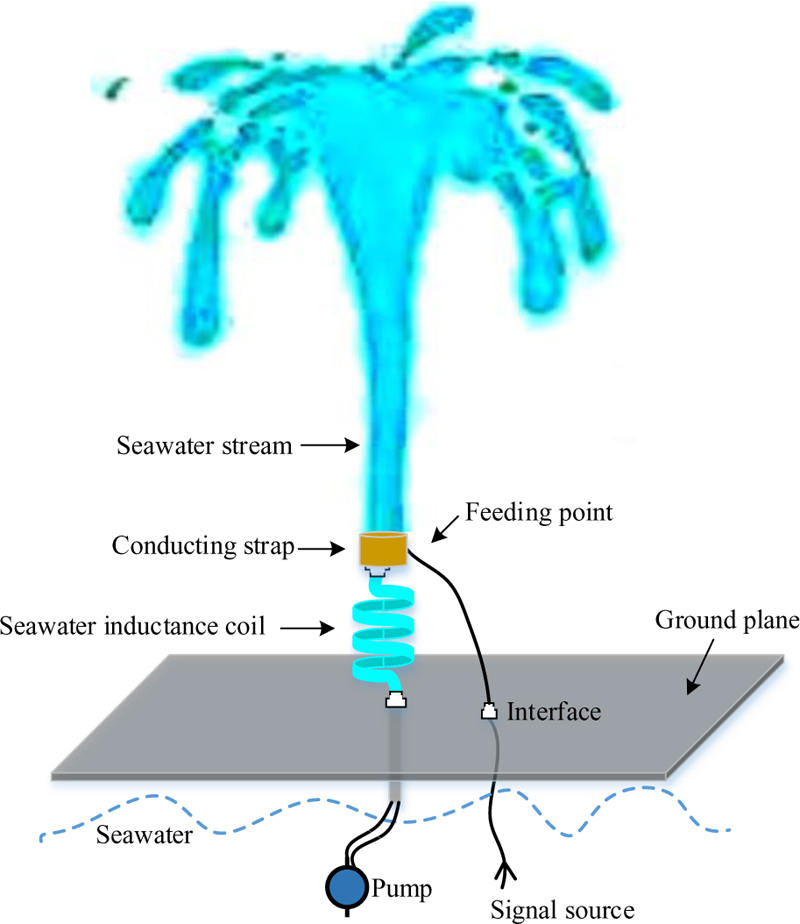
Figure 1: Schematic of a dynamic seawater monopole antenna isolated by a seawater inductance coil.
III. THE PRINCIPLE OF INDUCTIVE ISOLATION
The inductive isolation shown in Fig. 1 consists of an inductance element formed by the flow of spiral seawater connected to the root of the seawater monopole antenna. When the antenna works at high frequency, it presents a high impedance characteristic, which isolates the upper seawater antenna radiator from the lower seawater surface. The seawater inductance has sufficient impedance characteristics at high frequency, equivalent to the insulator’s function at the bottom of the common metal pole monopole antenna.
A. Impedance characteristics of the seawater inductance
The spiral seawater inductor is an inductance element that presents a distributed capacitance between the turns of the spiral seawater inductor and the DC resistance . The equivalent circuit diagram formed by these three elements is shown in Fig. 2. The contribution of to the overall impedance (Z) of the seawater inductance is significant [13], as shown in Equation (1). is related to the radius of the seawater inductance, the average turn spacing, and the diameter of the seawater coil, as shown in Equation (2). Equation (3) presents the inductive resistance that is, the isolation impedance. The greater the value of , the more significant the isolation effect.
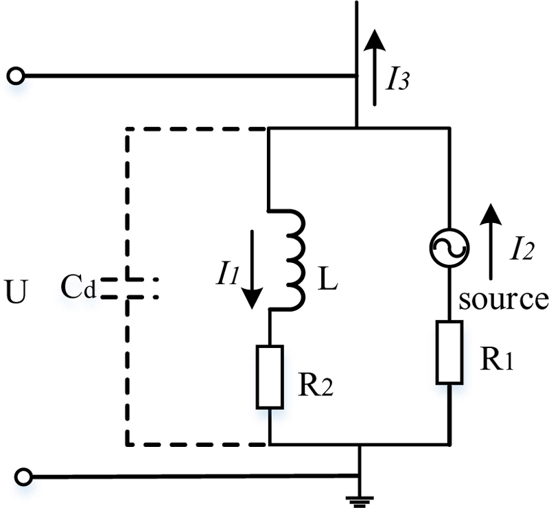
Figure 2: Equivalent circuit diagram for the inductance isolation of seawater.
| (1) | |
| (2) | |
| (3) |
where is the electrical conductivity of seawater, is the permeability of seawater, is the angular frequency, is the radius of the seawater inductance, is the number of turns of the seawater coil, is the diameter of the seawater coil, is the average turn spacing, which can be calculated as , is the length of the water coil, and is the seawater inductance, which is expressed as
| (4) |
where is given by in [14].
B. Radiation characteristics
The seawater spiral coil or ferrite ring that satisfies the inequation is considered to isolate the following radiation current:
| (5) |
The greater the value of , the lower the value of , and the greater the value of .
IV. SIMULATIONS
Based on the above theoretical analysis, an inductance isolation structure of the dynamic seawater antenna was designed. The structure design has a significant impact on the radiation characteristics of the antenna. The relationship between radiation efficiency and frequency is determined through the simulation while taking into consideration the parameters , N, ,and .
It can be seen from Figs. 3-6 that the radiation efficiency of the dynamic monopole seawater antenna with seawater inductance is generally improved for different parameters, especially at a higher frequency band. However, the radiation efficiency decreases in some frequency bands depending on the selection of parameters. At a certain frequency, the radiation efficiency varies with the change of the inductance parameters of seawater, as shown in Fig. 3. When the average turn spacing is 0.2, the radiation efficiency of the entire band is higher than that without the isolation inductance. The radiation efficiency is 80% at 350 MHz, while at this frequency, if the average turn spacing is 0.25 or 0.3, the radiation efficiency is lower than that without the isolation inductance. However, in other frequencies, such as the frequency interval of less than 300 MHz, when the average turn spacing is 0.3, the radiation efficiency with the isolation inductance is significantly better than that without using it. It can also be seen that when the average turn spacing is 0.5, the obtained radiation efficiency is 39% at 110 MHz, which is higher than that of 35% obtained in [9]. Similarly, in Figs. 4-6, according to the difference of Dr, r, and n parameters, the appropriate operating frequency is selected, and the radiation efficiency can always be better than that without the isolation inductance. It can be seen from Fig. 6 that the higher radiation efficiency is at 215-245 MHz, which parameter of isolation inductance is consistent with the experiment. Therefore, the parameters of the seawater antenna can be reasonably optimized according to the operating frequency during the actual use.
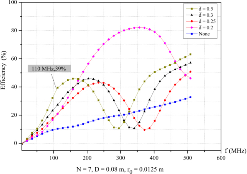
Figure 3: Relationship between efficiency and frequency at different values.
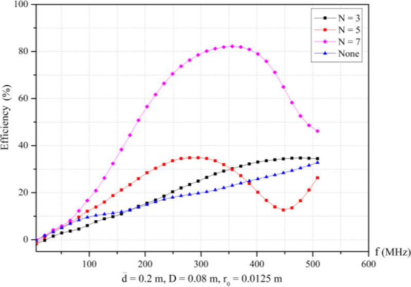
Figure 4: Relationship between efficiency and frequency at different N values.
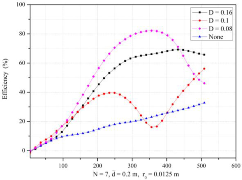
Figure 5: Relationship between efficiency and frequency at different D values.
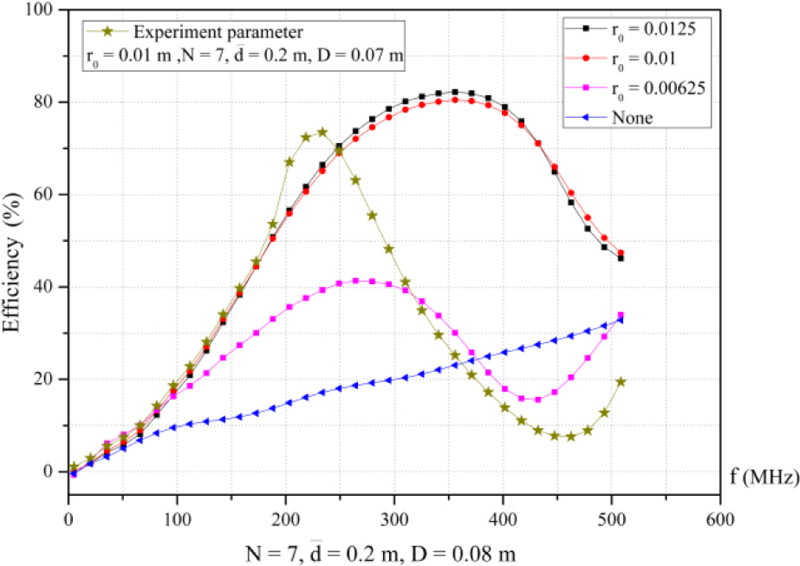
Figure 6: Relationship between efficiency and frequency at different values.
V. EXPERIMENT
To verify the isolation effect of the inductive reactance part, the transceiver system shown in Fig. 7 is constructed. The transmitter is made of the seawater monopole antenna and an ICOM radio. The receiver is made of a ferrite antenna and a G39 software receiver model, which is used to measure the received average mean carrier power. Before transmitting, the voltage standing wave ratio (VSWR) is measured by network analyzer connected with the seawater antenna in order to choose the optimal working frequency.
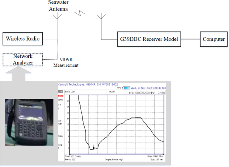
Figure 7: Experiment of the transceiver system.
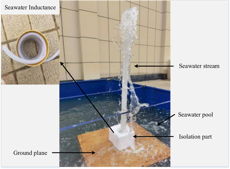
Figure 8: The seawater antenna with isolation part.
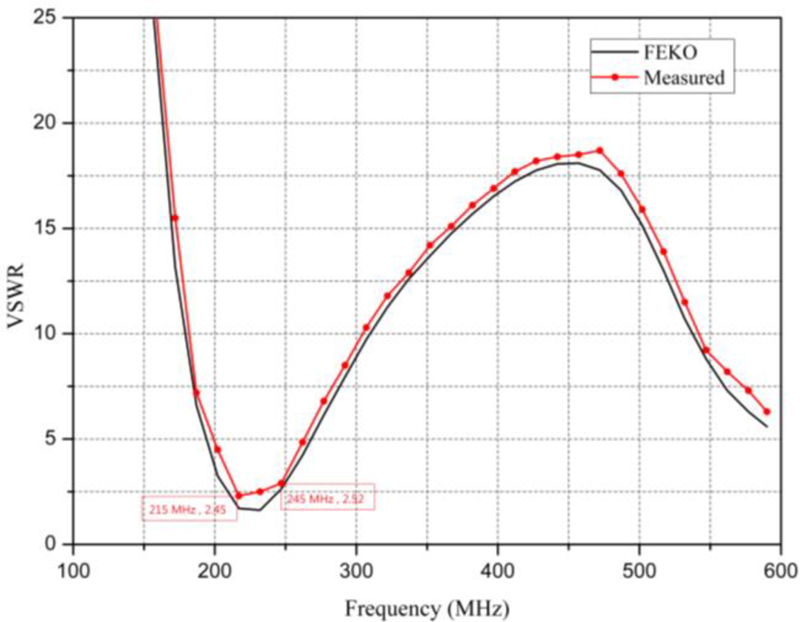
Figure 9: VSWR of the seawater antenna with inductance isolation.
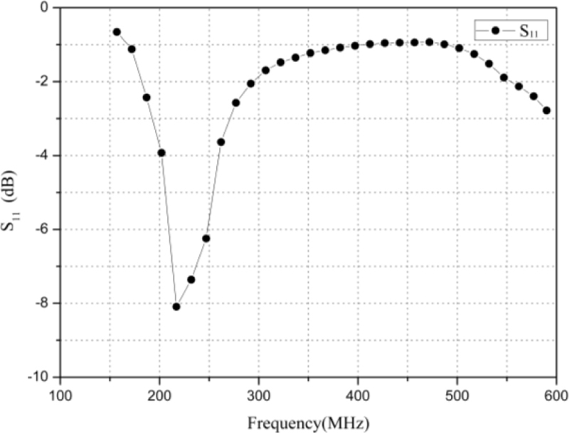
Figure 10: S of the seawater antenna with inductance isolation.
The dynamic seawater monopole antenna with seawater inductance isolation and direct feeding shown in Fig. 8 was placed in a 35 m seawater test pool. At the bottom of the antenna, there is a metal foil plate connected with seawater. , , , and the seawater inductance are equal to 1 cm, 7, 7 cm, 0.2 m, and 220 H, respectively. The seawater stream draws out from the seawater pool by a bump to form a seawater antenna having a height of 1.3 m and a diameter of 4 cm. The seawater antenna is used as a transmitting antenna. Within the frequency range of 215-245 MHz, the VSWR can be determined using a network analyzer, as shown in Fig. 9. The green line in Fig. 6 represents the simulation results of the radiation efficiency of the antenna with the experiment parameters. Because the VSWR is less than 2.52 within the frequency range of 215-245 MHz, the loss of reflection power in this interval is 18.65% according to the relationship between the reflection coefficient and VSWR. Radiation efficiency is the ratio of antenna radiation power to input power, which is difficult to measure directly. While the radiation efficiency is related to matching characteristics and the loss of the antenna, and the seawater antenna has a higher conductivity, the radiation efficiency of the seawater antenna can be greater than 70%, assuming the resulting loss is almost 10%. This is consistent with the simulation. Figure 11 shows the measured and simulated radiation pattern. In the experiment, it is measured once per 20 degrees in the largest radiation direction (theta = 55). Table 1 shows the mean value of the received carrier power with and without seawater inductance isolation. It can be seen that the value of in the case of inductance isolation is higher by 10 dB than that without isolation. Therefore, the method of inductive resistance can be used to increase the radiation efficiency.

Figure 11: Directivity of the seawater antenna with inductance isolation.
Table 1: Mean values of (dBm) with a receiving noise of 120 dBm
| Operating Frequency | 215 MHz | 225 MHz | 235 MHz | 245 MHz |
|---|---|---|---|---|
| with seawater inductance isolation |
68 | 65 | 64 | 62 |
| without seawater inductance isolation |
79 | 74 | 73 | 74 |
VI. CONCLUSION
In this paper, an improved dynamic seawater antenna is proposed. The radiation efficiency of the proposed antenna is improved using the inductance isolation method. This method solves the problem of direct connection between the radiation body of the dynamic seawater antenna and the seawater, which makes the radiation current flow into the seawater, leading to the low radiation efficiency. The simulation and experiment show that the proposed method can improve the radiation efficiency of the dynamic seawater antenna, and it can be greater than 70%. Optimization design is an important part of seawater antenna induction design. In future research, the optimization algorithm of seawater parameters can be further studied, which could lead to better efficiency of radiation. The seawater inductance is perfectly combined with the single polar seawater antenna in structure.
In future work, we aim at conducting a sea test. The sea environment can verify the greater low-frequency segment radiation characteristics, and the impact of the sea waves on the radiation efficiency can be further analyzed, which is a factor that should be considered inpractice.
ACKNOWLEDGMENT
This work was supported by the National Natural Science Foundation of China (41774021; 41874091; 42074074) and National Natural Science Foundation of China Youth Fund (62101579).
REFERENCES
[1] C. Hua and Z. Shen, “Sea-water half-loop antenna for maritime wireless communications,” Proceedings of the 2015 IEEE 4th Asia-Pacific Conference on Antennas and Propagation (APCAP), Indonesia, Bali Island, June 2015.
[2] X. Pan, Z. Hu, M. Zheng, Z. Ren, and Q. Chen, “A UHF sea-water array antenna for maritime wireless communications,” CSAA/IET International Conference on Aircraft Utility Systems (AUS 2353), China, Guiyang, June 2018.
[3] F. Sun, X. Lei, Q. Xu, X. Kong, H. Wang, and G. Zhang, “An attitude independent liquid dielectric resonant antenna,” IEEE Antennas and Wireless Propagation Letters, vol. 21, no. 11, pp. 1-4, 2022.
[4] Y. Kosta, “Liquid antenna,” Proceedings of IEEE AP-S Int. Symp. Dig., USA, CA, June 2004.
[5] H. Fayad and P. Record, “Broadband liquid antenna,” Electronics Letters, vol. 42, no. 3, pp. 133-134, 2006.
[6] E. Paraschakis, H. Fayad, and P. Record, “Ionic liquid antenna,” Proceedings of the Proc. IEEE Int. Workshop Antenna Tech.: Small Antennas and Novel Metamaterials, Singapore, Mar. 2005.
[7] L. Xing, Y. Huang, S. Alja’afreh, and S. Boyes, “A monopole water antenna,” Proceedings of IEEE 2012 Loughborough Antennas and propagation Conference (LAPC), United Kingdom, Leicestershire, Nov. 2012.
[8] G. Li, G. Gao, L. Bian, and Z. Lu, “A tunable antenna with the combination of two kinds of liquid materials,” Applied Computational Electromagnetics Society (ACES) Journal, vol. 32, no. 11, pp. 966-973, 2017.
[9] C. Hua, Z. Shen, and J. Lu, “High-efficiency seawater monopole antenna for maritime wirelesscommunications,” IEEE Trans. Antennas Propag. vol. 62, no. 12, pp. 5968-5973, 2014.
[10] SPAWAR, “Sea water antenna system,” SSC Pacific, San Diego, CA, Apr. 2011. [Online] http://www.public.navy.mil/spawar/Pacific/TechTransfer/ProductsServices/Pages/SeaWaterAntennaSystem.aspx and https://www.youtube.com/watch?v=9tIZUhu21sQ.
[11] A. Chatterjee, S. Chatterjee, S. Chatterjee, S. Ray, P. Adhikary, and B. Roy, “Analysis of sea water liquid antenna,” Proceedings of the 2020 4th International Conference on Electronics, Materials Engineering and Nano-Technology (IEMENTech), India, Kolkata, Oct. 2020.
[12] C. Hua and Z. Shen, “Shunt-excited sea-water monopole antenna of high efficiency,” IEEE Trans. Antennas Propag. vol. 63, no. 11, pp. 5185-5190, 2015.
[13] Y. Wang, X. Luo, Y. Zhang, N. Zhang, and J. Gao, “Distributed capacitance of spiral coils and its magneto-capacitance effect,” Applied Physics, pp. 44-49, 2013. [Online, Mar. 2013] http://www.hanspub.org/journal/app.html.
[14] Inductance Calculation Manual, China Machine Press, 1990.
BIOGRAPHIES

Lihua Li was born in Hubei Province of China. She received her bachelors and masters degrees from the Naval Engineering University. She is studying for a Ph.D. degree in Naval Engineering University. The main research direction is wireless communication. Currently working as an associate professor in the Communication Engineering Teaching and Research Section of Naval Engineering University, mainly responsible for teaching and research tasks. She has published many papers in international conferences and journals and has been invited many times.

Menglei Xiu was born in Anhui Province of China. He received a bachelor of Science and Technology in 2016 and a masters degree from Naval University of Engineering in 2022. He is studying for a doctors. degree in Naval University of Engineering. He worked as an assistant in the Department of Communication Engineering at Naval University of Engineering. The main research direction is wireless communication. A total of 3 articles have been published in international conferences and journals and have been indexed.

Shimin Feng (corresponding author) received his B.S., M.S., and Ph.D. in 2009, 2001, 2015 from Naval Engineering University. The main research direction is wireless communication. Currently working as an associate professor in the Communication Engineering Teaching and Research Section of Naval Engineering University, mainly responsible for teaching and research tasks. He has published several papers in international conferences and journals.
ACES JOURNAL, Vol. 38, No. 12, 952–957
doi: 10.13052/2023.ACES.J.381204
© 2023 River Publishers