Investigating the Distribution of Induced Electric Field Generated by Double Square Semicircle Coil in Transcranial Magnetic Stimulation
Yong Wang, Zhengguo Li, Jianyang Li, Haiyang Zhang, Enzhong Gong,and Liantao Shi
1Institute for Carbon-Neutral Technology
Shenzhen Polytechnic University, Shenzhen 518055, China
*Lizhengguo@szpt.edu.cn, enzhong@szpu.edu.cn, xiaoshi1108@outlook.com
2School of Electronic and Information Engineering
University of Science and Technology Liaoning, Anshan 114000, China
wy1764515601@163.com, Lijianyang928@126.com, zhy1083005453@126.com
Submitted On: August 6, 2023; Accepted On: March 7, 2024
ABSTRACT
Transcranial magnetic stimulation (TMS) is a physical technique that modulates the human brain nervous system and can be used as a non-invasive treatment for neurological diseases. To address the problem of poor focusing performance of TMS coils, this study first designs a new coil geometry, Double Square Semicircle (DSS) coil, based on traditional coil stimulation characteristics. Second, this study uses the Sim4Life finite element simulation software to compare the stimulation characteristics of DSS coil and six traditional coils under the head model, proving that the induced electric field generated by DSS coil has high-focusing performance. Third, this paper explores the effects of four physical parameters - the distance between the human brain model and the coil, different stimulation directions, coil size and coil bending angle - on the spatial distribution of the induced electric field. After the above simulation experiments, the optimal design scheme of DSS coil is found. Experimental results show that, compared with several traditional coils, the focusing effect can be improved by up to 77.49%, proving that DSS is a high-focusing performance TMS coil, which is suitable for future TMS high-precision treatment needs.
Index Terms: Finite-element method, focality, Sim4Life, stimulation depth, stimulation intensity.
I. INTRODUCTION
The mechanism of action of transcranial magnetic stimulation (TMS) technology in treating psychiatric disorders has been explored [1], and the magnetic stimulation coils, a key component, have received much attention. Efforts have been made to find a coil with superior focality performance to treat psychiatric disorders as effectively as possible [2–6]. Stimulation coils play an essential role in transcranial magnetic stimulators as the component that generates the time-varying electromagnetic field.
The geometry of the stimulation coils [7] affects the distribution of the electromagnetic field in the skull. In 1985, Barker [8] and others designed a single round stimulation coil, which were extremely simple to construct and easy to fabricate and operate. However, its disadvantage was also evident, as the single round coils could have performed better in focality. In 1988, Ueno designed a figure of eight (FOE) coil structure consisting of two identical round coils connected tangentially. The induced electric fields generated at the coil tangency points are superimposed in a unified direction to achieve good focusing function. Later, Cohen and Cuffin confirmed the excellent focality of the FOE coils through extensive simulation experiments [9]. FOE coils are currently the most mature coils used in magnetic stimulation therapy [10–12]. Many new coils have evolved, such as Biconical coils [13], Cloverleaf coils [14], Slinky coils [15–16], Flex Miniaturized coils [17] and FOE coils with a shield [18]. To meet the need for deeper stimulation, H-coils were proposed by Fiocchi et al. in 2016 [19]. In the following years, various combinations of coils began to appear, such as new Biconical coils [20], Semiellipse coil pair [21] and Butterfly coils [22]. Deng et al. [7] conducted a simulation analysis of 50 stimulation coils, covering all coils developed to date. By comparing the relationship between peak intensity, stimulation depth and focality of 25 coils, Fang et al. [21] found that focality and depth attenuation is related to the coils winding geometry, but this is not the case with peak field strength. The latter depends on other factors affected by the choice of coil design. Most coil design parameters (angle, number of windings, distance) have a much greater impact on peak field strength than focality and depth attenuation. For all three parameters, the dependence on the overlap between the two coil wings of the simulated zigzag coils is similar only. Therefore, there is great flexibility in designing coils with similar focality and depth attenuation but different peak field strengths [23]. However, most are currently in the research stage and need continuous experimental validation before they can be applied in practice.
This paper presents a novel geometric structure of TMS coil, the Double Square Semicircle (DSS) coil, which can generate a localized induced electric field in the brain and enhance focality. Using the finite element method, spatial distribution of the induced electric field in the brain is analyzed in detail, including its intensity, focality and stimulation depth. Simulation results demonstrate the high-focusing advantage of the DSS coil. Moreover, this study investigates the effects of geometric structure variations (bending angle, structure size, distance between the coil and the model) on the induced electric field and identifies the optimal design parameters of the coil.
II. MATERIALS AND METHOD
We utilized Sim4Life three-dimensional human tissue medical electromagnetic simulation software (Sim4Life) to model the stimulation coil model. The line thickness is ignored and a line coil model is drawn based on the size of the coil. The position of the coil is adjusted to increase current stimulation. Additionally, the coil is designed as a closed loop, allowing current to exist throughout the entire coil. For intracranial magnetic stimulation experiments, Sim4Life’s (EM LF Quasi-Static) low-frequency simulator is employed to calculate the distribution of electromagnetic fields at a frequency of 10 kHz. The function is evaluating human brain response and adaptation in low-frequency electromagnetic fields.
A. Model establishment
Based on the stimulation characteristics of an 8-figure coil and semiellipse coil, this paper proposes a new coil structure, the DSS coil, aimed at exploring the spatial distribution of the induced electric field resulting from superimposition of the square coil and the semicircle coil. This coil is divided into two layers. The upper layer comprises a double square structure with a side length of 45 mm, contributing to the decay of transient current [21]. The lower layer consists of a double semicircle structure with a radius of 25 mm, enhancing the strength and depth of the central induced electric field [1]. The thickness of both parts of the new coil is 1 mm, with a coil spacing of 2 mm. When the currents in the same direction are superimposed, the electric field strength will increase, so increasing the current stimulation in the same direction will significantly change electric field strength. Current direction is indicated by a white arrow in Fig. 1, with a current amplitude of 2000 A. The coil models built by Sim4Life shown in Figs. 1 (a) and (b) are the upward and main views of the coils, respectively. The current direction of the square coils is the same as that of the semi-circular coils. The current direction of the left half coils is counterclockwise and the current direction of the suitable half coils isclockwise.
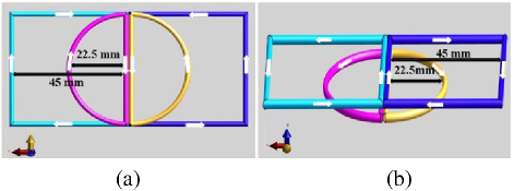
Figure 1: DSS coil structure diagrams: (a) upward view of DSS coil and (b) main view of DSS coil.
The human head model used in this paper is sourced from the Population Head Model (PHM) library available on the IT’IS website [24–26]. A surface-based head model is imported into the commercial software Sim4Life and is discretized in three orthogonal directions with a maximum spatial step of 1 mm. This model aims to replicate the natural structure of the human head as accurately as possible. The human head model selected in this paper includes seven parts (Fig. 2).
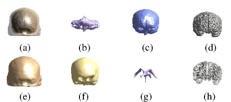
Figure 2: Tissues of the PHM head model: (a) headform and (b-h) the seven parts of the headform: cerebellum, cerebrospinal fluid, gray matter, skin, skull, ventricles and white matter.
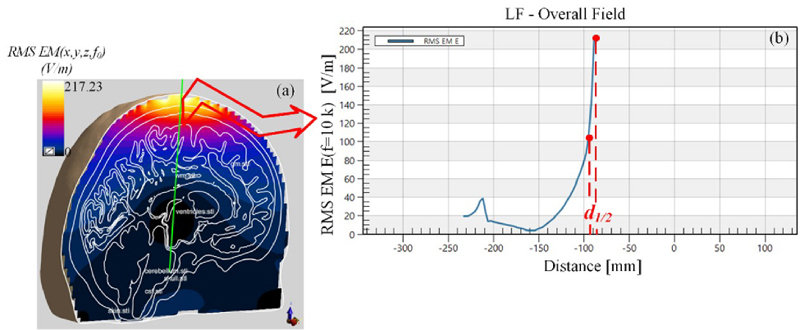
Figure 3: (a) Electric field simulation of the vertical section of the model and (b) electric field is distributed vertically along the green line.
Considering that the conductivity and permittivity of different parts of the brain tissue are different, the choice of skin conductivity in dosimetry studies depends on the anatomical accuracy of skin characterization in each head model [27]. Specifically, when considering a model that incorporates skin into a thick and uniform scalp tissue, the average conductivity value assigned to it should consider all included skin and subcutaneous tissues (dermis, SAT, muscle). Thus, skin will strongly affect the calculated electric field. Therefore, in order to simulate the head more realistically, accurate conductivity and permittivity of each tissue are needed. In order to make the control experiment more meaningful, this paper sets the skin conductivity to 0.0002 S/m and the permittivity to 1130 [27]. Other tissues will use the accurate conductivity and permittivity of the head tissues obtained by the IT’IS website at 10 kHz frequency. As shown in Table 1, the scalp is composed of different tissues, including muscle and fat. The actual conductivity is higher than the conductivity shown in Table 1 (scalp conductivity in Table 1 is the conductivity value at 10 kHz), which may cause deviation in the calculation results. However, scalp tissues at different locations are different and using the volume conductivity values that reflect this point in the subsequent simulation may be a more realistic method [28].
Table 1: Conductivity and permittivity of different layers of brain tissue
| Brain Tissue | Electrical Conductivity (S/m) | Dielectric Constant |
| Cerebellum | 0.1 | 22500 |
| Cerebrospinal fluid | 2.0 | 10900 |
| Gray matter | 0.1 | 22200 |
| Skin | 0.0002 | 1130 |
| Skull | 0.02 | 52200 |
| Ventricle | 0.5 | 905 |
| White matter | 0.1 | 12500 |
B. Evaluating indicators
We chose commonly used methods in recent years to evaluate and compare the stimulation effects of different magnetic stimulation coils.
(1) Stimulation intensity: defined as the maximum induced electric field strength (E) on the cortex [4].
(2) Stimulation depth: defined as the longest distance dfrom the position of E on the cortical surface to the position that the induced electric field strength is E/2[3], as shown in Fig. 3. The induced electric field generated in the skull will cause changes in neural activity in the brain; the larger the d value, the deeper the position of the brain area that can be stimulated, which is a more conducive to the treatment of the deep lesions in the skull.
(3) Focality: focusing situation of the induced electric field generated by the TMS coil in the human target area, usually measured by the focusing area. According to the definition of Deng et al. [29], the head stimulation area that exceeds half of the maximum electric field strength is defined as the focality. Focality represents the ability of the coil to produce an induced electric field that is concentrated in a certain area, and a three-dimensional solid evaluation formula is used to roughly calculate the focusing area [29]:
| (1) |
where d is used to quantify the half-value depth of electric field penetration and V is the cumulative volume of the half-value region exposed to the electric field EE/2. The smaller the value, the smaller the focus area, the higher the focus, and the better the effect.
III. RESULTS AND DISCUSSION
A. Comparison of DSS coil with multiple traditional coils
To highlight the advantages of the DSS coil in focusing performance, this paper selects three types of coils (Circular, FOE, Double Conical) to compare with the DSS coil in an experimental study. Since the DSS coil is designed as a double-layer structure, and considering the influence of the number of components on the spatial distribution of the induced-electric field [4], the Double Circular, FOE and double-cone coils are also added (Fig. 4). The radius of the Circular coil is 45 mm, and the radius of the FOE coil and the double cone coil is 45 mm. The coil structure is a single body structure.
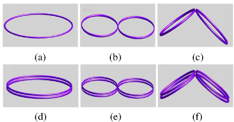
Figure 4: Schematic diagram of six types of coil structures: (a) Circular coil, (b) 8-figure coil, (c) Conical coil, (d) Double Circular coil, (e) Double 8-figure coil and (f) Double Conical coil.
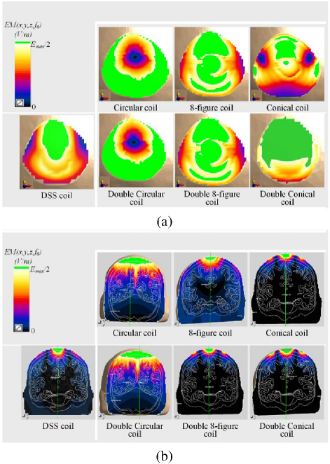
Figure 5: (a) Distribution of electric field on the XY horizontal cross-section and (b) the XZ vertical cross-section in the model under the action of various coils.
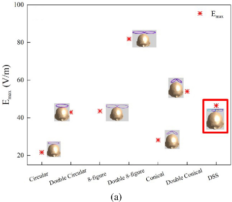
Figure 6: (a) Stimulation intensity of seven types of coils, (b) stimulation focality of seven types of coils and (c) stimulation depth of seven types of coils.
The focusing characteristics [5] of the coil are simulated and analyzed, as shown in Fig. 5, comparing the induced electric field cross sectional distribution of six traditional coils with the DSS coil. This experiment chooses to perform horizontal cross section and XZ vertical cross section analysis at the maximum value of the model. Among them, through the post-processing function of Sim4Life simulation software, the part greater than E/2 is highlighted (green), which is the effective stimulation area. On the horizontal plane, compared with DSS coil, the Conical coil has the smallest green part, but is also the most dispersed, and the focusing performance of the Conical coil is weaker than that of the DSS coil. Similarly, on the XZ vertical plane, we observe that the Circular coil and the Double Circular coil are the most affected by the stimulation. According to the data shown in Fig. 6, to ensure the focusing of the coil, the lower layer of the DSS coil is designed as a small semi-circle. As shown in Figs. 6 (a) and (b), the DSS coil is not only outstanding in terms of stimulation depth and stimulation intensity but also has obvious advantages in focality. Compared with the Double Circular coil, the Double 8-figure coil and the double cone coil, focality is reduced by about 91%, 77.19% and 11.91%, respectively. This study asserts that the DSS coil demonstrates high-focusing performance, aligning well with the future development needs of precise TMSapplications.
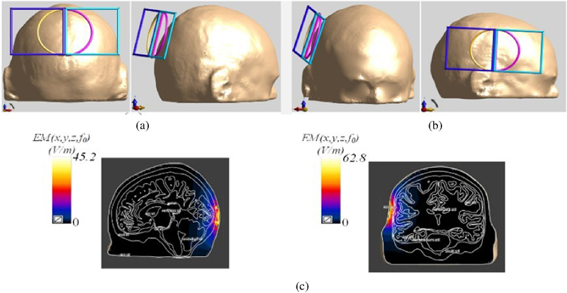
Figure 7: Placement and stimulation effect of the DSS coil: (a) coil is placed on the back of the head model, (b) coil is placed on the left side of the head model and (c) cross-sectional diagrams of the electric-field stimulation of the coil at two positions.
B. Stimulus effects in different directions
Performance of the DSS coil may vary depending on the position of the coil in the scalp. To provide a more comprehensive evaluation of the new coil, it is positioned on both the side and the back of the head, maintaining a distance of 10 mm from the scalp. The performance characteristics are then simulated at these two positions. The stimulation-position diagram and the stimulation effect cross-section diagram of the coil are shown in Fig. 7. The electric field’s stimulation direction remains perpendicular to the coil’s plane and points toward the head model. This variation in positioning accounts for the differing brain tissue compositions across the scalp.
Table 2: Stimulus results of DSS coils at different placement positions
| Coil Position | E(V/m) | d (mm) | S (cm) |
| Left side of head | 45.2 | 6.2 | 6.4 |
| Dorsal side of head | 62.8 | 4.2 | 6.2 |
If we extract the electric field stimulation information, and calculate the stimulation depth and focality, we get the contents of Table 2. From the perspective of electric field intensity, the electric field value induced by the back coil is 17.6 V/m higher than that induced by the side coil. However, the stimulation depth is just the opposite. The difference in focus between different positions is not significant, only 0.2 cm. Compared with the top position of the head, the induced electric field value of the left coil is still the highest, but the focus of the top coil of the head is the best. The reason is the result of the difference in tissue type and thickness of the back and sides of the head model.
C. Influence of the distance between the stimulation coils and the scalp on intracranial induction focusing field distribution
In this section, by changing the relative position of the coil and the top of the scalp by 1 mm, reducing the distance between them, and keeping the relative position of the coil and the head unchanged, the relative position of the coil and the top of the scalp is adjusted to form seven groups of coil combinations. The change of the coil distance relative to the head is shown in Fig. 8.
Table 3 shows how changing the distance affects both the maximum electric field and the stimulation depth. There is a negative correlation between these two variables: as they decrease, so does their maximum value. The coil-head distance affects both variables: when it increases, so does their minimum value; when it decreases, so does their maximum value. Stimulation depth reaches its highest point at a distance of either 7 mm or 8 mm, with values of 4.8 mm, and DDS coil reaches its lowest point at a distance of only 5 mm, with values of only 4.0 mm. The focus is calculated for each pair and plotted against their maximum electric field values in Fig. 9.
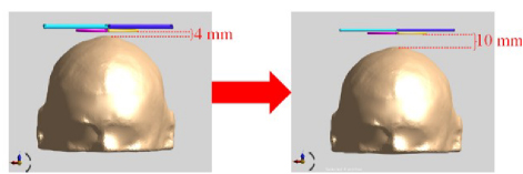
Figure 8: Variation of the distance of the coils relative to the head.
Table 3: The influence of the distance between coil and model on electric field intensity and the stimulus depth
| Distance (mm) | E (V/m) | (mm) |
| 4 | 75.4 | 4.2 |
| 5 | 72.9 | 4.0 |
| 6 | 62.0 | 4.7 |
| 7 | 57.8 | 4.8 |
| 8 | 48.9 | 4.8 |
| 9 | 48.6 | 4.7 |
| 10 | 46.5 | 4.7 |
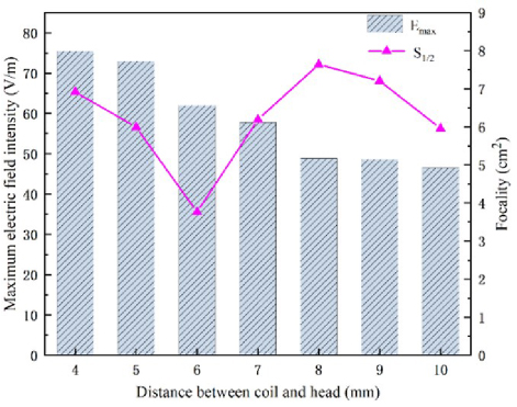
Figure 9: Influence of relative distance between the whole coils and the scalp on maximum electric field andfocality.
Figure 9 shows how the electric field strength, the stimulation depth and the focus vary with the distance between the coil and the head. Electric field strength is highest when the distance is 4 mm, indicating a stronger intracranial stimulation field as the coil gets closer to the head. Focus is lowest when the distance is 6 mm, implying a more concentrated stimulation field with a smaller focusing area. Stimulation depth is highest when the distance is either 7 mm or 8 mm, reaching the deepest parts of the brain. Focus changes significantly with the distance: it is 7.6 cm at 8 mm, 3.8 cm at 6 mm, and 3.2 cm less at 6 mm than at 4 mm. Therefore, the optimal distance for both focality and stimulation depth is 6 mm, where focus is minimal and stimulation depth is 4.7 mm. Electric field strength is also relatively high at this distance, about 63 V/m. In the subsequent experiments, we set the vertical distance from the coil to the human brain model to be 6 mm.
D. Effect of coil structure size on the distribution of intracranial induced stimulation field
In this section, we divide the magnetic stimulation coils into three groups based on their coil structures: semicircular, square and integral. We vary the size of each coil structure by 1 mm as a unit and examine how it affects the focusing performance. Figure 10 shows the size changes of the coil structures.
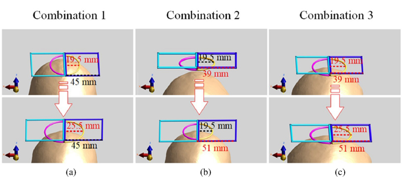
Figure 10: Dimensional variation diagram of coil structure: (a) Combination 1: the size of the square coil unchanged, while the radius of the semicircle coil incrementally, (b) Combination 2: the size of the semicircle coil unchanged, while the square coil incrementally and (c) Combination 3: the overall coil structure size adjusted incrementally.
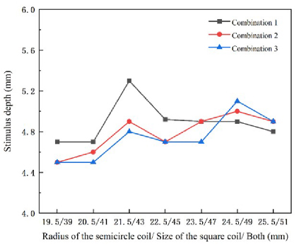
Figure 11: Depth of stimulation for three combinations of coil size changes.
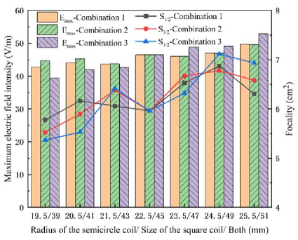
Figure 12: Effect of coil size on electric field strength and focality.
Since the length of the semicircle and the square varies in the same steps, we use the same scale for the X axis in Fig. 11. Figure 11 shows the stimulation depth results for the three coil combinations, with the gray, red and blue lines representing the results of the three experimental groups. The study found that the stimulation depth increases gradually as the coil size increases, and reaches two peaks when the coil size is 21.5 mm/43 mm (the radius of the semicircle/the side length of the square) and 24.5 mm/49 mm for all three combinations. At the first peak, the stimulation depth is maximized by increasing the size of the semicircular coil (Combination 1), with a depth value of 5.3 mm.
Figure 12 summarizes and plots the effects of coil size changes on the electric field strength and the focality, using bar charts and curves. The horizontal axis shows the coil structure size, the left vertical axis shows the maximum induced electric field strength, and the right vertical axis shows the focality. The blue, red and gray curves represent the focusing area values for Combination 3, Combination 2, and Combination 1, respectively. The purple, green and orange bars represent the maximum induced electric field values for the three combinations. Figure 12 shows that, in Combination 1, increasing the radius of the semicircle from 19.5 mm
To investigate the effects of coil bending on TMS applications, we bent the coils to various degrees and analyzed how the coil bending characteristics influenced the stimulation area and focus. This is because coil bending can concentrate the electric field to some extent, thereby reducing the stimulation area and achieving higher focus. We divided the magnetic stimulation coils into three groups: Combination 4; bent circular coils, Combination 5; bent square coils, Combination 6; bent whole structure. The three groups had bending ranges from 0 to 70, with increments of 10. The results of coil bending are shown in Fig. 13.
The stimulation depth results of the three groups of coils are shown in Fig. 14 as line graphs, where blue, red and gray lines represent the results of the three groups. The effect of coil bending on stimulation depth first increases and then decreases. The maximum stimulation depth of the three coils is achieved at 40 bending, with Combination 4 having the largest stimulation depth of 8.7 mm and Combination 6 having the smallest stimulation depth of 8.1 mm. Therefore, by bending the coils appropriately, they can be closer to the head, increase the stimulation depth and reach deeper brain tissues, and enhance the feasibility of disease treatment.
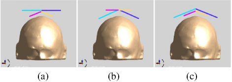
Figure 13: Three bending combinations of DSS coils: (a) Combination 4; keep the square coil unchanged and bend only the circular coil, (b) Combination 5; keep the circular coil unchanged and bend only the square coil and (c) Combination 6; bend the whole coil.
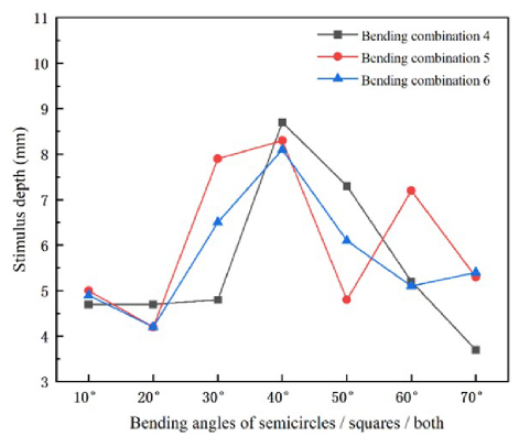
Figure 14: Stimulation depth of coil bending.
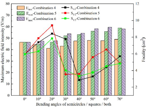
Figure 15: Influence of coil curvature on electric field strength and focality.
Bar and line graphs summarizing electric field intensity and focality of coil bending angle are shown in Fig. 15. The horizontal axis is the bending angle (0 70), the left vertical axis represents the maximum value of electric field intensity, and the right vertical axis represents the focus area value, which is the coordinate of the curve. The purple, green and orange bars in Fig. 15 represent the electric field values of Combinations 6, 5 and 4, respectively, and the green, red and black curves represent the focus of the three combinations. When the coil is bent, the distance between the model and the coil decreases, which inevitably leads to the enhancement of the induced electric field. As can be seen from Fig. 15, the maximum electric field value appears at 60 bending of Combination 6, and the minimum value appears at 20 bending of Combination 4. In addition, it is found that the maximum focus value is shown at 20 bending of Combination 5, and the minimum focus value is shown at 40 bending of Combination 4. The trend of the coil’s focusing performance is that the focus value first increases, then decreases and subsequently increases again. When the coil is bent at 20, it reaches the maximum value and the coil’s focusing performance is the worst; when the coil is bent from 20 to 40, it is a steep drop stage, reaching a trough, and then the focus rises with the bending of the coil angle. The above experiments demonstrate that bending the coil can enhance both the maximum electric field and focusing performance, with a maximum increase of 28% and 51.7%, respectively.
In Combinations 5 and 6, the focality drops sharply and the stimulation depth rises sharply in the bending angle range of 20 30. In Combination 4, the same cliff-like change occurs between 30 and 40. In order to prevent this phenomenon caused by too large test interval, this section conducts more detailed experimental simulation on the angles with significant changes. This paper divides the magnetic stimulation coil into three combinations. Combination 7: bend the semi-circular coil; the bending range is 3040; Combination 8: bend the square coil; Combination 9: bend the whole structure; the bending range is 2030, and the minimum angle step unit is set to 2.5. Performance comparison between the stimulation depth and the focus is obtained and shown in Fig. 16.
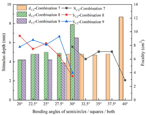
Figure 16: Refined simulation of coils.
Figure 16 shows that the coil bending angle of groups 7, 8 and 9 in the range 37.540 and 27.530 causes a drastic change in the stimulation depth and focus. This phenomenon may be caused by the uneven distribution of brain tissue inside the human head model selected by this study.
F. Data analysis
The main idea of coil design is to find coils with deeper stimulation depth and better focusing performance. Based on preliminary modeling, as shown in Figs. 11 and 12, Combination 1, which sets the size of the semi-circular and square coils to 22.5 mm and 45 mm, respectively, has the optimal performance in terms of stimulation intensity, stimulation depth and focality. On this basis, bending experiments are carried out. Combination 4, which bends the semi-circular coil by 40, has the optimal performance in terms of stimulation intensity, stimulation depth and focality. Compared with the traditional Double 8-figure and Double-Conical coils, although it is slightly inferior in stimulation intensity, it increases the stimulation depth by 7.35% and 10.47%, respectively, and reduces the focality by 77.49% and 42.10%, respectively, greatly improving the focusing performance of the TMS coil. Therefore, DSS is a TMS coil with high focality.
IV. CONCLUSION
This study applies the novel electromagnetic simulation software Sim4Life to perform finite element simulation of the induced field of the head electric stimulation coil. By simulating six classical coils, the focusing information of the head electric stimulation field is obtained and its stimulation characteristics are analyzed. A new coil is proposed, and the study applies the variable control method to simulate the stimulation field. Compared with the six classical coils, the new DSS coil greatly outperforms them in terms of focus. Furthermore, the effects of four physical parameters, namely, the distance between the human brain model and the coil, the stimulation direction, the coil size and the bending angle, on the spatial distribution of the induced electric field of the DSS coil are explored. After the above simulation experiments, it was found that the optimal design scheme of the DSS coil is that the distance between the model and the coil is 6 mm, the size of the semi-circular and square coils are 22.5 mm and 45 mm, respectively, and the semi-circular coil is bent by 40. Compared with the Double 8-figure and Double-Conical coils, the focus of the DSS coil is reduced by 77.49% and 42.10%, respectively, which proves that the new coil structure proposed in this paper can achieve better results in the focusing of the stimulation field. In addition, the coil has high flexibility and can change the position and angle of stimulation to better match different patients. In the future, researchers can explore different coil combinations and configurations to increase the stimulation depth of the coil and enhance its stimulation performance, making it better suited for future medicaltreatments.
ACKNOWLEDGMENT
This study was funded by Shenzhen Double Carbon Technical Talent Innovation and Development Research Center (grant number: 521-6022210008Q).
REFERENCES
[1] O. F. Afuwape, H. Oya, A. D. Boes, and D. C. Jiles, “Measurement and modeling of the effects of transcranial magnetic stimulation on the brain,” IEEE Trans. Magn., vol. 57, no. 2, pp. 1-5, Feb. 2021.
[2] J. C. Lin, “Transcranial magnetic stimulation therapy for depression and psychiatric disorders,” IEEE Microwave Mag., vol. 17, no. 8, pp. 23-93, Aug. 2016.
[3] S. Chang, X. Wei, Z. Zhang, J. Wang, M. Lu, and G. Yi, “Twin coil design considerations for depth and focality in transcranial magnetic stimulation,” IEEE Trans. Magn., vol. 54, no. 11, pp. 1-5, Nov. 2018.
[4] H. Xiong, Q. Y. Li, and J. Z. Liu, “Performance optimization and simulation research of new coil for transcranial magnetic stimulation based on improved particle swarm optimizer,” IEEE Trans. Magn., vol. 57, no. 12, pp. 1-11, Dec. 2021.
[5] M. Dannhauer, Z. Huang, L. Beynel, E. Wood, Y. Li, H. Palmer, S. Hilbig, S. Davis, R. Cabeza, and L. Appelbaum, “TAP: Targeting and analysis pipeline for optimization and verification of TMS coil placement,” Brain Stimul., vol. 14, no. 6, p. 1620, Dec. 2021.
[6] Y. Roth, A. Amir, Y. Levkovitz, and A. Zangen, “Three-dimensional distribution of the electric field induced in the brain by transcranial magnetic stimulation using figure-8 and deep H-coils,” Clin Neurophysiol., vol. 24, no. 1, pp. 31-38, Feb. 2007.
[7] Z. D. Deng, S. H. Lisanby, and A. V. Peterchev, “Electric field depth-focality tradeoff in transcranial magnetic stimulation: simulation comparison of 50 coils designs,” Brain Stimul., vol. 6, no. 1, pp. 1-13, Jan. 2013.
[8] A. T. Barker, R. I. Jalinous, and I. L. Freeston, “Noninvasive magnetic stimulation of the human motor cortex,” Lancet, vol. 1, pp. 1106-1107, May 1985.
[9] D. Cohen and B. N. Cuffin, “Developing a more focal magnetic stimulator. Part I: Some basic principles,” J. Clin Neurophysiol., vol. 8, no. 1, pp. 102-111, Jan. 1991.
[10] S. Lu, H. Jiang, C. Li, B. Hong, P. Zhang, and W. Liu, “Genetic algorithm for TMS coil position optimization in stroke treatment,” Front. Pub. Health, vol. 9, p. 794167, Mar. 2022.
[11] H. Magsood, F. Syeda, K. Holloway, I. C. Carmona, and R. L. Hadimani, “Safety study of combination treatment: deep brain stimulation and transcranial magnetic stimulation,” Front. Hum. Neurosci., vol. 14, Apr. 2020.
[12] D. H. Kim, G. E. Georghiou, and C. Won, “Improved field localization in transcranial magnetic stimulation of the brain with the utilization of a conductive shield plate in the stimulator,” IEEE Trans. BioMed., vol. 53, no. 4, pp. 720-725, Apr. 2006.
[13] E. R. Lontis, M. Voigt, and J. J. Struijk, “Focality assessment in transcranial magnetic stimulation with double and conecoils,” Clin. Neurophysiol., vol. 23, no. 5, pp. 463-472, Oct. 2006.
[14] B. J. Roth, P. J. Maccabee, L. P. Eberle, V. E. Amassian, M. Hallett, J. Cadwell, G. D. Anselmi, and G. T. Tatarian, “In vitro evaluation of a 4-leaf coils design for magnetic stimulation of peripheral nerve,” Electroencephalogr. Clin. Neurophysiol., vol. 93, no. 1, pp. 68-74, Feb. 1994.
[15] K. P. Zimmermann, and R. K. Simpson, “‘Slinky’ coils for neuromagnetic stimulation,” Electroencephalogr. Clin. Neurophysiol., vol. 101, no. 2, pp. 145-152, Apr. 1996.
[16] C. Ren, P. P. Tarjan, and D. B. Popovic, “A novel electric design for electro-magnetic stimulation-the slinky coils,” IEEE Trans on Biomedical Eng., vol. 42, no. 9, pp. 918-925, Sep. 1995.
[17] M. Colella, D. Z. Press, R. M. Laher, C. E. McIlduff, S. B. Rutkove, A. M. Cassarà, F. Apollonio, A. P. Leone, M. Liberti, and G. Bonmassar “A study of flex miniaturized coils for focal nerve magnetic stimulation,” Medical Physics, vol. 50, no. 3, pp. 1779-1792, Mar. 2023.
[18] C. Zhao, S. Q. Zhang, Z. P. Liu, and T. Yin, “Simulation study to improve focality of a figure eight coils by using a conductive shield plate and a ferromagnetic block,” IEEE Trans. Neural Syst. Rehab. Eng., vol. 23, no. 4, pp. 529-537, July 2015.
[19] S. Fiocchi, Y. Roth, A. Zangen, P. Ravazzani, and M. Parazzini, “Assessment of the electric field induced by deep transcranial magnetic stimulation in the elderly using h-coil,” Applied Computational Electromagnetics Society (ACES) Journal, vol. 31, no. 6, pp. 636-643, June 2016.
[20] Y. X. Wu, H. Y. Yu, and Z. W. Liu, “Numerical investigation of the magnetic and electric field distributions produced by biconical transcranial magnetic stimulation coils for optimal design,” IEEE Trans. Magn., vol. 54, no. 11, pp. 1-5, Nov. 2018.
[21] X. Fang, H. F. Ding, Y. H. Huang, J. Zhou, Q. J. Wang, and Z. F. Zhao, “Improved intracranial induced electrical field in transcranial magnetic stimulation with semiellipse coil pair,” IEEE Trans. Applied Superconductivity, vol. 28, no. 3, pp. 1-6, Apr. 2018.
[22] P. Rastigi, E. G. Lee, R. L. Hadimani, and D. C. Jiles, “Transcranial magnetic stimulation-coils design with improved focality,” AIP Adv., vol. 7, no. 5, p. 056705, May 2017.
[23] E. G. Lee, P. Rastogi, R. L. Hadimani, D. C. Jiles, and J. A. Camprodon, “Impact of non-brain anatomy and coil orientation on inter- and intra-subject variability in TMS at midline,” Clinical Neurophysiology, vol. 129, no. 9, pp. 1873-1883, Sep. 2018.
[24] J. S. Elam, M. F. Glasser, M. P. Harms, S. N. Sotiropoulos, J. L. R. Andersson, G. C. Burgess, S. W. Curtiss, R. Oostenveld, L. J. Larson-Prior, J. M. Schoffelen, M. R. Hodge, E. A. Cler, D. M. Marcus, D. M. Barch, E. Yacoub, S. M. Smith, K. Ugurbil, and D. C. Van Essen, “The Human Connectome Project: A retrospective,” NeuroImage, vol. 244, no. Suppl C, p. 118543, Dec. 2021.
[25] S. Gabriel, R. W. Lau, and C. Gabriel, “The dielectric properties of biological tissues: II. Measurements in the frequency range 10 Hz-20 GHz,” Phys. Med. Biol., vol. 41, pp. 2251-2269, Nov. 1996.
[26] S. Zhang, P. Silburn, N. Pouratian, B. Cheeran, L. Venkatesan, A. Kent, and A. Schnitzler, “Comparing current steering technologies for directional deep brain stimulation using a computational model that incorporates heterogeneous tissue properties,” Neuromodulation, vol. 23, no. 4, pp. 469-477, June 2020.
[27] M. Colella, A. Paffi, V. D. Santis, F. Apollonio, and M. Liberti, “Effect of skin conductivity on the electric field induced by transcranial stimulation techniques in different head models,” Physics in Medicine Biology, vol. 66, no. 3, p. 035010, Jan. 2021.
[28] T. Wagner, U. Eden, J. Rushmore, C. J. Russo, L. Dipietro, F. Fregni, S. Simon, S. Rotman, N. B. Pitskel, C. Ramos-Estebanez, A. P. Leone, A. J. Grodzinsky, M. Zahn, and A. V. Cabre, “Impact of brain tissue filtering on neurostimulation fields: A modeling study,” NeuroImage, vol. 85, Special SI, pp. 1048-1057, Jan. 2014.
[29] Y. Wang, Y. H. Yang, Y. H. Qi, E. Z. Gong, H. Y. Zhang, L. T. Shi, and Z. G. Li, “Investigating the electric field distribution in the human brain model induced by a high focality transcranial magnetic coil,” AIP Adv., vol. 13, no. 10, p. 105211, Oct. 2023.
BIOGRAPHIES
Yong Wang graduated from the School of Telecommunication, University of Science and Technology Liaoning, majoring in electronic information. He is currently pursuing his PhD at Jilin University with a research direction of bioelectromagnetism and human health.
Zhengguo Li was born in 1972 and holds a Ph.D. from Central South University. Li is a leading professional in Guangdong Province, a specially appointed scholar professor in Pengcheng, Shenzhen, and a high-level talent in Shenzhen. For many years, he has been committed to research on new energy vehicle technology, power electronics technology, carbon neutrality technology, school enterprise cooperation, and collaborative education. His current research direction is new energy vehicle technology and electromagnetic compatibility technology.
Jianyang Li graduated from the School of Telecommunication, University of Science and Technology Liaoning, majoring in electronic information. His research direction is the research and development of transcranial magnetic therapy instrument. He is currently a communication engineer at China Mobile Communications Co. Ltd.
Haiyang Zhanggraduated from the College of Telecommunications, University of Science and Technology Liaoning, and was jointly trained with the Academician Workstation of Ju Dongying, Shenzhen Vocational and Technical University. His major was control engineering, and his research direction is human health and power equipment.
Enzhong Gong was born in 1994. He is a master’s degree holder, assistant researcher, mainly engaged in research in new energy technology, electromagnetic compatibility technology, and other fields.
Liantao Shi received his B.S. degree from Huaqiao University in 2018 and his M.S from the University of Science and Technology Liaoning in 2022. His main research direction is embedded systems and computer vision semantic segmentation.
ACES JOURNAL, Vol. 40, No. 1, 51–61
doi: 10.13052/2025.ACES.J.400107
© 2025 River Publishers