Design of a New Balanced Side Slotted Vivaldi Antenna with Director using Genetic Algorithm
Xiaoyan Zhang, Yuxu Hu, and Aiyun Zhan
1School of Information Engineering
East China Jiaotong University, Nanchang, 330013, China
xy_zhang3129@ecjtu.edu.cn, huyuxu_2021@163.com, 707290432@qq.com
2State Key Laboratory of Millimeter Waves, Nanjing, China
Submitted On: August 20, 2023; Accepted On: December 20, 2023
ABSTRACT
Generally, side slotting and directional techniques can improve the performance of a conventional Vivaldi antenna (CVA), but the optimal structure and distribution of slots and directors may be irregular or even complex, requiring significant manual effort, thus limiting the design possibilities. In this paper, a genetic algorithm (GA) is introduced to assist in designing and optimizing a new type of balanced side slotted Vivaldi antenna with director (SSVAD). The methods of artificial intelligence make the process of searching for the optimal structure of such a multi-objective and multi-dimensional problem simpler and more diverse. The GA-generated SSVAD antenna consists of a CVA and 34 slots with varying lengths, as well as 5 metal strips. It has a compact size of mm (or 0.320.410.007, where is the lowest operating frequency of 2.48 GHz). The measured results show that the antenna has a peak gain 0 dBi over 2.48-10.88 GHz and 5 dBi over 4.6-10.88 GHz with S-10 dB standard, and exhibits directional characteristics at most of the operating frequencies. Since the measured results are basically consistent with the simulation ones, the effectiveness of the designed scheme has been proven.
Keywords: Balanced side slotted Vivaldi antenna, director, genetic algorithm optimization, ultra-wide band.
I. INTRODUCTION
Due to the characteristics such as stable directional radiation pattern, ultra-wideband, high gain, and low profile, the Vivaldi antenna has aroused the researchers’ intense interest. Miniaturization and high gain are its main design difficulties [1]. To solve these issues, a method of side slotting has been introduced into conventional Vivaldi antenna (CVA) designs [2–5]. For example, in 2017, sparse irregular slots were etched on the radiators of a CVA, achieving a compact design with bandwidth of 3.9-9.15 GHz [2]; in the same year, dense comb-shaped slits with identical spacing and length were applied to a conventional antipodal antenna (CAVA) design, expanding its bandwidth from 1.8-4 GHz to 1.65-18 GHz and improving low-frequency gain as well [3]; in 2021, a new balanced side-slotted Vivaldi antenna (SSVA) with three pairs of triangular shaped slots was proposed, realizing a bandwidth of 3.05-12.2 GHz and a peak gain of 8.2 dBi [4]. In 2019, a Vivaldi antenna array was proposed for underwater communication. A linear conical array slot structure was applied to the traditional Vivaldi antenna, achieving an impedance bandwidth of over 55% with a return loss of 10 dB and a peak gain of 10.75 dBi [5]. Obviously, the side slotting technology can effectively improve the performance of the CVA/CAVA, but the shape features of the slots may be very complex and may need a long time to find a suitable one. Therefore, in order to improve design efficiency, the slots are usually assumed to have regular features and are uniformly distributed, which may result in the inability to obtain the optimal structure and limit the more possibilities of design.
To further improve the performance of the SSVA, a lens or a director is loaded at the front of its radiation patch, which can guide the energy distribution of the antenna along the end-fire direction, thereby enhancing its directivity. Specifically, the lens includes a protruding substrate [6, 7], as well as single-layer or multi-layer phase compensation metal strips [8, 9], increasing the size of the antenna. For example, in 2016, the substrate at the front end of the antenna was protruded into a semicircle, which reduced the phase error on the antenna aperture, but increased its size by 2070 mm [6]; in 2017, a three-layer phase correcting lens (PCL) was introduced into a CVA. Although it increased the antenna’s gain by 1.1-6.1 dB, it also resulted in an additional size of 5216.5 mm and a thickness of 15 mm [8]. In contrast, the director only occupies the clearance area of the antenna, so that the antenna can remain compact.
Generally, the director can be formed by adding higher permittivity dielectric elements [10], metal parasitic patches [1, 7, 9, 11], and conductor gratings [12–14]. For example, an elliptical metal director was loaded into SSVA, increasing its fractional bandwidth by 13% and gain by 0.2 dB in [11]; several rectangular gratings were used in a SSVA, resulting in a gain improvement of nearly 1 dB in [13]; some epsilon negative metamaterial cells are arranged in two flares of a CAVA in [14], enhancing the gain of the antenna by 3 dB in the 24-30 GHz frequency range. Similar to grooving technology, the size, shape, and position distribution of the director have an impact on the directivity of the antenna, so they also need to be carefully designed.
In order to shorten the time for manual design, intelligent search technologies, such as swarm intelligence algorithm [15–17] and genetic algorithm (GA) [18–19], have been applied to optimize antenna parameters. For example, a frequency selective surface (FSS)-loaded CAVA was optimized using honeybee mating optimization (HBMO) algorithm in [15], but the structure of the antenna itself has not been optimized; in [16], the optimal size of the slots of a notch band UWB antenna was obtained through a particle swarm optimization (PSO) algorithm. However, only the voltage standing wave ratio (VSWR) was tested, and its gain and co-polarization radiation patterns were given through simulation, so the algorithm’s performance has not been fully demonstrated; in [18], the heights of the rings of a lens antenna were optimized using GA. Compared with the swarm intelligence algorithms, GA is more widely used because it is less likely to fall into local optima prematurely, which reveals the enormous potential of GA in complex antenna design.
In this work, considering that SMA joint welding may cause a relatively large error in the antipodal antenna, as well as the research needs of the group in flexible antennas in the future, planar Vivaldi was selected as a reference in this design. The side slots and director of the SSVAD are jointly optimized and generated through GA, so their shapes and scales exhibit symmetric and random characteristics, making it difficult to achieve through manual design, as it requires extensive multi-objective and multi-dimensional simulation experiments. The measured results indicate that the antenna has a compact size, a bandwidth of 125.6%, and a peak gain of 8.47 dBi. Compared with published literatures, the proposed antenna has the advantages of miniaturization, relatively large fractional bandwidth, and high gain. Although the structure of the antenna appears complex, the GA approach make the process of searching for the optimal structure of such a multi-objective and multi-dimensional problem simpler and morediverse.
This manuscript is arranged as following. First, the design and optimization methods of the antenna are described in Section II. Then, the GA-generated SSVAD was fabricated and tested in Section III, and the measured results were compared with the simulation ones, all of which were presented. Finally, a conclusion is made in Section IV.
II. METHODS FOR ANTENNA DESIGN AND OPTIMIZATION
A. Basic structure of the CVA
The proposed antenna is designed based on a traditional structure, as shown in Fig. 1. It is printed on a FR4 substrate with relative dielectric constant () of 4.4, loss tangent of 0.025, and thickness (t) of 0.8 mm. The length (L) and width (W) of the substrate are 49 mm and 38.2 mm, respectively. This CVA consists of a coupler (as shown in Fig. 1 (a) and two radiating fins (as shown in Fig. 1 (b)). They are etched on two opposite sides of the substrate.
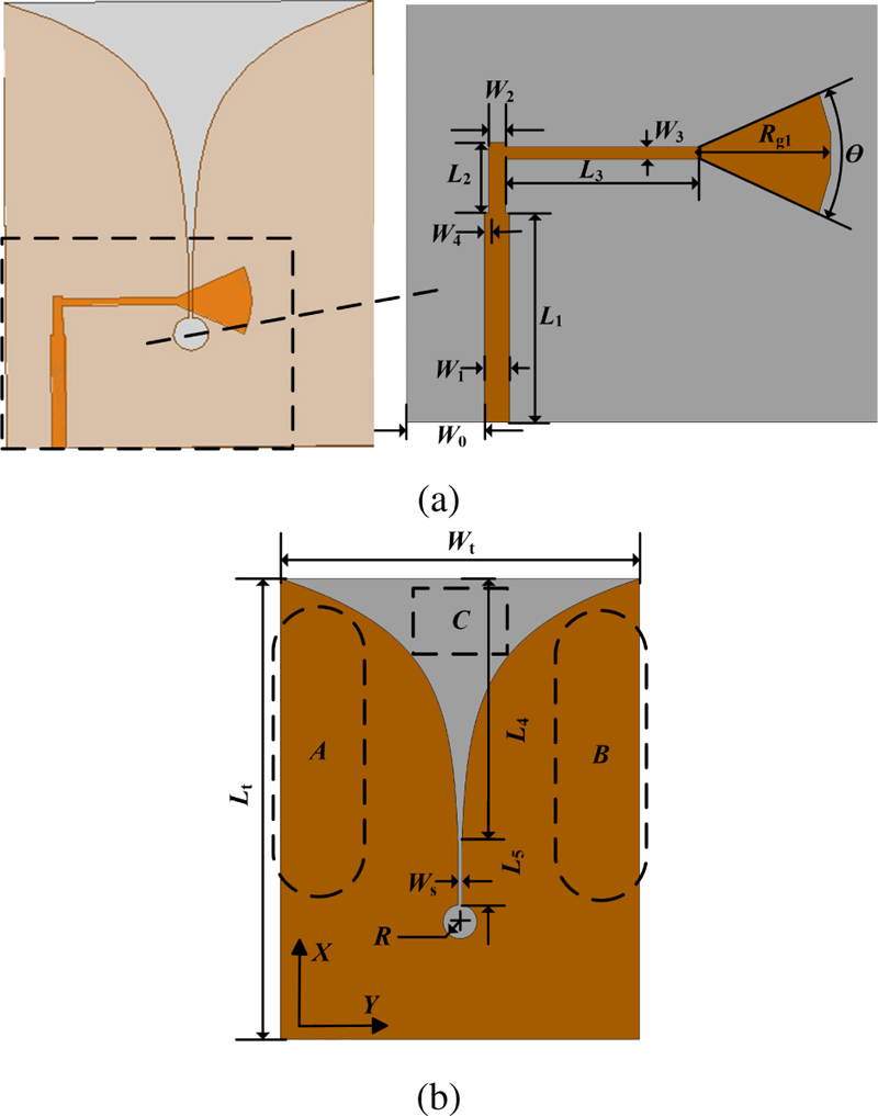
Figure 1: Basic structure of the Vivaldi antenna: (a) Its top view and (b) its bottom view.
The coupler includes a microstrip feed line, a microstrip-to-slot-line transition, and a fan-shaped stub. They are cascaded to match the impedance between the feeding and the tapered slot structure, thus enabling the antenna to maintain good impedance matching over a wide frequency band. Their parameters are represented by L, W, L, W, L, W, R. The width of the microstrip feed line that matches the characteristic impedance of 50 ohms can be calculated through following formulas [20]:
| (1) |
with
| (2) |
where t is the thickness of FR4 substrate and W is the width of the microstrip feeder .
The fins have exponential curves and a circular resonant cavity (with a radius of R) slotted at their intersection. The exponential curves of the fins are given as
| (3) |
where x and y represent the coordinates of the curve. The constant C and opening rate k are given by:
| (4) |
where L, W, and W are the length, width, and throat width of the aperture respectively. The distance between the aperture and the top of the circular cavity is L. Radiation occurs along the exponential curves. The circular cavity serves as an open circuit to minimize the reflections from the microstrip line to the microstrip-to-slot-line transition [12].
The regions A, B, and C shown in Fig. 1 (b) were selected for optimization. Specifically, side slotting technique is applied to the A and B regions, while the conductor gratings as the director have been introduced into the C region. The slots in region B are symmetrical and identical to A.
B. The proposed SSVAD design and optimization
Before optimization, the specific location of the slots and the total area they will occupy cannot be determined. Therefore, the A/B region is initialized as 36 evenly spaced etched slots along the X direction. Similarly, the region C is initialized with 6 metal strips. For ease of fabricating, each slot and strip are rectangular in shape. The specific optimization methods based on GA are as follows.
Considering the large number of the slots, their widths and the distance between adjacent slots are fixed as 0.5 mm, and only their lengths (numbered as L, n=1, 2, …, 36) are generated by GA. While, the director is only composed of 6 metal strips, so both their length (L, n=1, 2, …, 6) and width (W) can be optimized. These elements are arranged in parallel and the distance between the bottom edges of two adjacent elements is fixed as g. To avoid overlapping and excessive length of metal strips, L is set to 1.2 mm and W mm. In contrast, the size range limitations of L require more consideration. Firstly, the resonant wavelength caused by a slot with a length of L can be estimated as [21]
| (5) |
According to (5), the estimated length of the slots is 12.3-41 mm (corresponding to 3-10 GHz). Next, considering that the half width of CVA is W = 19.1 mm, and to avoid damaging the current distribution of the exponential curves, the length of the slots L- L needs to be shortened. Ultimately, they are controlled between 0 mm and 15 mm. The determination of the range for other L is also for the same reason.
The GA and a high frequency simulation software (HFSS) V15.1 are combined through an application programming interface (API). The former is used to search for the optimal parameters, while the latter attempts to apply them in antenna simulation. In order to minimize the reflection of the antenna within the frequency range of 3-10 GHz and ensure a higher gain, the fitness function is defined as the average return loss of the antenna at the sampling frequency:
| (6) |
with
| (7) |
and constraints:
| (8) |
where
| (9) |
Here, N refers to the number of discrete frequencies f; |S(f)| refers to the return loss of the antenna at f, and its standard is |S| 10 dB. The average return loss of the antenna is calculated using formula (6). When Fitness = 10, it indicates that the return loss of the target frequency band is larger than 10 dB; Gain(f) and Gain(f)are the peak gains of the GA generated antenna and the CVA (as shown in Fig. 1), respectively. Literature research [9, 22] has found that adding gratings can improve some of the high-frequency gain but has little effect on the low-frequency gain. The frequency at which the gain can be increased accounts for approximately 70-80% of the total frequency. Therefore, in order to reduce optimization time, A 0.8 is used as the standard for determining the optimal parameter, which means that the antenna gain of over 80% of frequencies is higher than that of CVA.
The flowchart of GA assisted antenna design is shown in Fig. 2. The parameters optimized using GA and their corresponding limiting ranges are listed in Table 1. Table 2 presents the main parameters of GA, such as population number, crossover rate, mutation rate, and maximum iteration number.
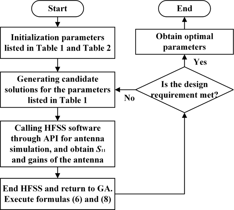
Figure 2: Design process of the GA-generated antenna.
Table 1: Parameters and their constraints
| Region | Parameter | Constraint (mm) |
|---|---|---|
| A/B | L-L, L-L | 0-3 |
| A/B | L- L | 0-15 |
| A/B | L- L | 0-9 |
| C | L-L | 0-7 |
| C | W-W | 0.5-1.2 |
Table 2: Main parameters of the GA
| Parameter | Value |
|---|---|
| Maximum iteration number | 100 |
| Crossover rate | 0.9 |
| Mutation rate | 0.05 |
| Deadline iterations | 62 |
| Gene length | 8 |
| Population number | 150 |
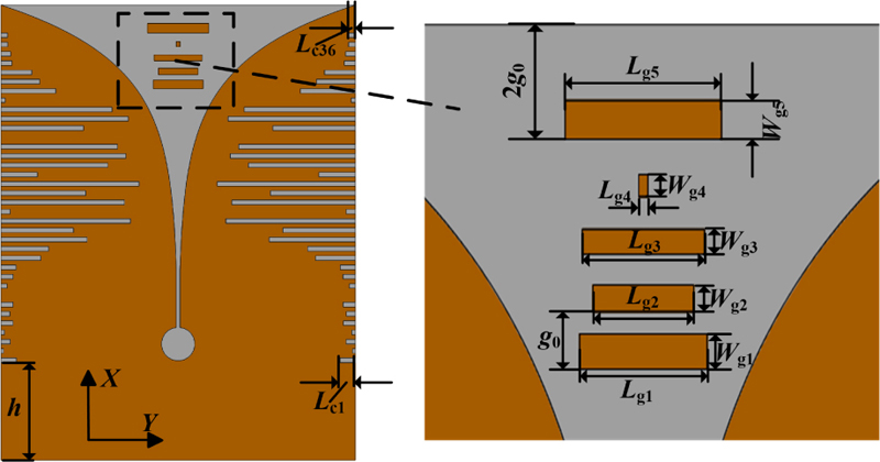
Figure 3: The structure of the proposed SSVAD.
The optimization process is performed on a PC with Intel Core i7 (3.4 GHz, 8-core) CPU and 32 GB RAM. After about 18 days of calculation, the structure of the proposed balanced GA-generated SSVAD antenna is shown in Fig. 3. After optimization, L, L, and L are 0, so the number of slots and metal strips are 34 and 5, respectively. The optimized parameters are shown in Table 3.
Table 3: Optimized parameters of the proposed SSVAD (unit: mm)
| Symbol | Value | Symbol | Value | Symbol | Value |
| W | 38.2 | W | 4.65 | W | 1.5 |
| W | 1 | W | 0.75 | W | 0.25 |
| Lc | 1.65 | Lc | 0.29 | Lc | 0.99 |
| Lc | 0.38 | Lc | 1.27 | Lc | 0.95 |
| Lc | 1.3 | Lc | 0 | Lc | 0.63 |
| Lc | 1.31 | Lc | 1.62 | Lc | 4.29 |
| Lc | 5.14 | Lc | 9.28 | Lc | 7.81 |
| Lc | 13.95 | Lc | 0.98 | Lc | 13.31 |
| Lc | 9.14 | Lc | 14.88 | Lc | 3.92 |
| Lc | 11.52 | Lc | 13.47 | Lc | 12.57 |
| Lc | 0 | Lc | 8.89 | Lc | 13.72 |
| Lc | 11.97 | Lc | 0.43 | Lc | 5.9 |
| Lc | 4.18 | Lc | 3.31 | Lc | 1.17 |
| Lc | 1.04 | Lc | 0.72 | Lc | 0.7 |
| Ws | 0.4 | L | 49 | L | 12.5 |
| L | 4.2 | L | 12.25 | L | 28.5 |
| L | 6.2 | h | 10.5 | Wg | 0.5 |
| Wg | 0.93 | Wg | 0.7 | Wg | 0.65 |
| Wg | 0.58 | Wg | 0 | g | 1.5 |
| Lg | 5.39 | Lg | 4.26 | Lg | 5.17 |
| Lg | 0.39 | Lg | 6.61 | Lg | 0 |
| R | 1.8 | 50 | Rg | 8.6 |
C. Antenna analysis
The current distribution on the radiation fins of the CVA, balanced SSVA and the proposed SSVAD at frequencies of 3.2, 7.2, and 9.2 GHz, is simulated and compared in Fig. 4. By comparing the current intensities in the D, E, and F regions, it can be clearly observed that the current of the CVA shown in Fig. 4 (a) is mainly distributed at the edges of the antenna radiation fins. In contrast, guided by the side slotting and the director, the surface currents of SSVA and SSVAD shown in Figs. 4 (b) and (c) diffuse toward the interior of the fins, thereby increasing the effective radiation area; and the director gathers the high-frequency radiation field of the antenna, thereby increasing the directionality of the antenna at high frequencies.
Figure 5 compares the simulated return loss of the CVA, balanced SSVA, and proposed SSVAD respectively. It can be seen that the operating frequency range of CVA is 3.1-10 GHz (or a fractional bandwidth of 105%). After side slotting and loading director, S decreased by 6.63 dB, 6.32 dB, 12.44 dB, 11.12 dB, and 10.33 dB at 3.1 GHz, 4.51 GHz, 7.24 GHz, 9.03 GHz, and 10.82 GHz, respectively, so its operating frequency is expanded to 2.79-11.17 GHz (up to 122%).
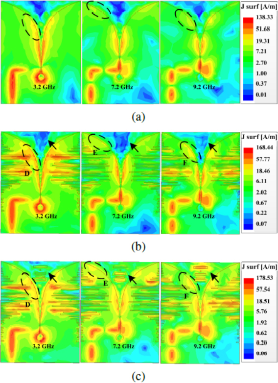
Figure 4: Comparison of simulated surface current distribution of (a) CVA, (b) balanced SSVA, and (c) SSVAD at different frequencies (3.2, 7.2, and 9.2 GHz).
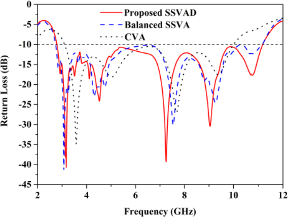
Figure 5: Comparison of the simulated return loss for CVA, balanced SSVA, and proposed SSVAD.
The realized gains of the three antennas at 2.79-11.17 GHz are compared in Fig. 6, which verifies that after loading director and applying side slotting technology, the antenna gains become higher.
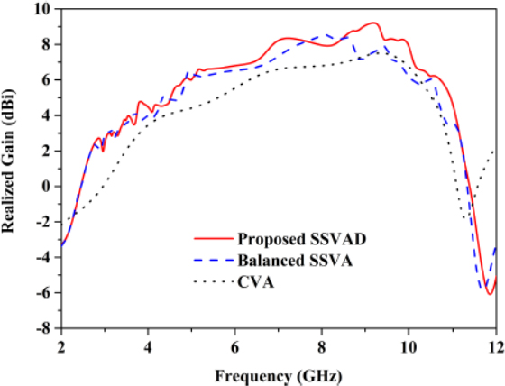
Figure 6: Comparison of the simulated realized gains of CVA, balanced SSVA, and proposed SSVAD.
Comparison of performance between the proposed SSVAD and other antennas listed in [4, 11, 13, 15, 17, 22, 23] is presented in Table 4. Through comparison, it can be seen that the design of artificial intelligence assisted Vivaldi antennas is still limited. Although the structure of the antenna appears complex, the process of designing with GA approach is relatively simple. The proposed antenna has a size of 0.320.40.007, a bandwidth of 8.4 GHz, and a peak gain of 8.47 dBi. It can be inferred that the proposed antenna achieves a wide impedance bandwidth and a high gain with a relatively compact size.
Table 4: Specification and performance comparison between reference antennas and the proposed antenna
| Ref. (Years) | Intelligent Optimization Technology | Optimization Methods | Size | Bandwidth / Fractional Bandwidth | Peak Gain |
| [4] | – | Diagonal slot | 8.2 | ||
| [11] | - | Rectangular strip | 7.2 | ||
| [13] | – | Bottle-shaped slots+Rectangular strip | 8.8 | ||
| [15] | HBMO | Multi layer FSS | 10.1 | ||
| [17] | FSS | 10 | |||
| [22] | – | Star-shaped slot +Artificial material lens +Dielectric lens | 9.2 | ||
| [23] | - | Rectangular slot | 5.43 | ||
| This work | GA | Rectangular slot+ irregular Rectangular strip | 8.47 |
III. MEASURED RESULTS
The proposed antenna has been fabricated, and its photographic images are shown in Fig. 7. Its return loss is tested by the Agilent Network Analyzer (Keysight E5071C) and compares with the simulated ones, which are shown in Fig. 8. Measured results show that the proposed antenna has a -10 dB impedance bandwidth of 2.48-10.88 GHz (125%). Although there are some differences between the test results and simulated results (as ultra-wideband (UWB) antennas are very sensitive to fabrication tolerance), the overall trend is consistent.
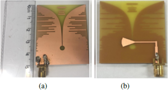
Figure 7: Photographs of the fabricated proposed antenna: (a) Top view and (b) bottom view.
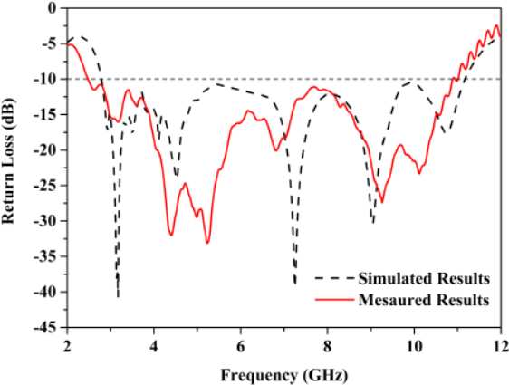
Figure 8: Simulated and measured return loss of the proposed antenna.
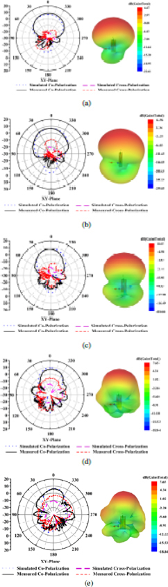
Figure 9: Simulated and measured radiation patterns of the proposed antenna in the XY-plane and 3D far-field radiation pattern: (a) 5.2 GHz, (b) 6.2 GHz, (c) 7.2 GHz, (d) 9.2GHz, and (e) 10.2 GHz.
The measured 2-D radiation patterns in the XY-plane and 3-D far-field radiation pattern of the proposed antenna at frequencies of 5.2, 6.2, 7.2, 9.2, and 10.2 GHz are shown in Figs. 9 (a), (b), (c), (d), and (e), respectively. Their co-polarization to cross-polarization ratios at 5.2 GHz, 6.2 GHz, 7.2 GHz, and 9.2 GHz are 27.8 dB, 27.51 dB, 26.2 dB, 23.2 dB, and 17.1 dB. They are all greater than 10 dB, indicating that the polarization interference of this antenna is small.
The variation of the peak gains of the designed antenna over 2-12 GHz is shown in Fig. 10. The maximum value of the test results is 8.47 dBi, which appears at 5.2 GHz and deviates from the simulation (the peak gain is 9.2 dBi at 9.2 GHz), which may be due to fabrication tolerance.
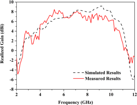
Figure 10: Simulated and measured realized gains of the proposed antenna.
IV. CONCLUSION
In this paper, the GA approach is applied in generating edge slots of the SSVAD and determining the positions and scales of the slots and director elements. The proposed antenna has a compact size of 0.320.410.007. It can operate at 2.48-10.88 GHz. The peak gain within this frequency range is 8.47 dBi. Compared with the traditional manually designed antennas, the proposed antenna has a more complex structure and a better performance. The design process of these structures can be separated from manual participation, reflecting the advantages of intelligent design. In the future, we will continue to seek a more efficient artificial intelligence algorithm to accelerate search speed. And, constraints such as directionality and cross polarization ratio will be introduced into the fitness function. These research approaches will be further applied to the design of flexible antennas.
ACKNOWLEDGMENT
The authors wish to acknowledge the support of the Jiangxi Provincial Department of Education Project (GJJ2200622), Open Project of Millimeter Wave Key Laboratory (K202431).
REFERENCES
[1] H. Zhu, X. Li, L. Yao, and J. Xiao, “A novel dielectric loaded Vivaldi antenna with improved radiation characteristics for UWB application,” Applied Computational Electromagnetics Society (ACES) Journal, vol. 33, no. 4, pp. 394-399, Apr. 2018.
[2] M. Z. Mahmud, M. T. Islam, M. Samsuzzaman, S. Kibria, and N. Misran, “Design and aarametric investigation of directional antenna for microwave imaging application,” IET Microwaves, Antennas & Propagation, vol. 11, no. 6, pp. 770-778, May 2017.
[3] M. Moosazadeh, S. Kharkovsky, J. T. Case, and B. Samali, “Antipodal Vivaldi antenna with improved radiation characteristics for civil engineering applications,” IET Microwaves, Antennas & Propagation, vol. 11, no. 6, pp. 796-803, May 2017.
[4] H. Özmen and M. B. Kurt, “Radar-based microwave breast cancer detection system with a high-performance ultrawide band antipodal Vivaldi antenna,” Turkish Journal of Electrical Engineering and Computer Sciences, vol. 29, no. 5, pp. 2324-2345, Sep. 2021.
[5] P. Soothar, H. Wang, B. Muneer, Z. A. Dayo, and B. S. Chowdhry, “A broadband high gain tapered slot antenna for underwater communication in microwave band,” Wireless Personal Communications, vol. 116, no. 2, pp. 1025-1042, Aug.2019.
[6] Y. Zhang, E. Li, C. Wang, and G. Guo, “Radiation enhanced Vivaldi antenna with double-antipodal structure,” IEEE Antennas and Wireless Propagation Letters, vol. 16, pp. 561-564, Mar. 2017.
[7] X. Zhang, Y. Chen, M. Tian, J. Liu, and H. Liu, “A compact wide-band antipodal Vivaldi antenna design,” International Journal of RF And Microwave Computer-aided Engineering, vol. 29, no. 4, pp. 1-6, Oct. 2018.
[8] X. Li, G. Liu, Y. Zhang, L. Sang, and G. Lv, “A compact multi-layer phase correcting lens to improve directive radiation of Vivaldi antenna,” International Journal of RF and Microwave Computer-aided Engineering, vol. 27, no. 7, pp. 1-12, Apr. 2017.
[9] A. S. Dixit and S. Kumar, “The enhanced gain and cost-effective antipodal Vivaldi antenna for 5G communication applications,” Microwave and Optical Technology Letters, vol. 62, no. 6, pp. 2365-2374, Feb. 2020.
[10] J. Bourqui, M. Okoniewski, and E. C. Fear, “Balanced antipodal Vivaldi antenna with dielectric director for near-field microwave imaging,” IEEE Transactions on Antennas and Propagation, vol. 58, no. 7, pp. 2318-2326, July 2010.
[11] M. Samsuzzaman, M. T. Islam, M. T. Islam, A. A. S. Shovon, R. I. Faruque, and N. Misran, “A 16-modified antipodal Vivaldi antenna array for microwave-based breast tumor imaging applications,” Microwave and Optical Technology Letters, vol. 61, no. 9, pp. 2110-2118, Sep.2019.
[12] S. Guruswamy, R. Chinniah, and K. Thangavelu, “Design and implementation of compact ultra-wideband Vivaldi antenna with directors for microwave-based imaging of breast cancer,” Analog Integrated Circuits and Signal Processing, vol. 108, pp. 45-47, May 2021.
[13] J. J. Wang, J. W. Liu, Y. C. Fan, and Y. X. Bai, “A novel Vivaldi antenna for UWB detection,” Microwave and Optical Technology Letters, vol. 65, no. 3, pp. 826-843, Dec. 2023.
[14] A. S. Dixit and S. Kumar, “Gain enhancement of antipodal Vivaldi antenna for 5G applications using metamaterial,” Wireless Personal Communications, vol. 121, pp. 2667-2679, Dec.2021.
[15] P. Mahouti, A. Klzllay, O. Tari, A. Belen, M. A. Belen, and A. Caliskan, “Design optimization of ultra-wideband Vivaldi antenna using artificial intelligence,” Applied Computational Electromagnetics Society (ACES) Journal, vol. 36, no. 12, pp. 1594-1601, Dec. 2021.
[16] Y. Li, W. Shao, L. You, and B. Wang, “An improved PSO algorithm and its application to UWB antenna design,” IEEE Antennas and Wireless Propagation Letters, vol. 12, pp. 1236-1239, Oct.2013.
[17] F. Güneş, İ. Ö. Evranos, M. A. Belen, P. Mahouti, and M. Palandökenb, “A compact triband antipodal Vivaldi antenna with frequency elective surface inspired director for IoT/WLAN applications,” Wireless Networks, vol. 27, no. 5, pp. 3195-3205, June 2021.
[18] W. Yu, L. Peng, Y. Liu, Q. Zhao, X. Jiang, and S. Li, “An ultrawideband and high-aperture-efficiency all-dielectric lens antenna,” IEEE Antennas and Wireless Propagation Letters, vol. 20, no. 12, pp. 2442-2446, Dec. 2021.
[19] K. Kayalvizhi and S. Ramesh, “Design and analysis of reactive load dipole antenna using genetic algorithm optimization,” Applied Computational Electromagnetics Society (ACES) Journal, vol. 35, no. 3, pp. 279-287, Mar. 2020.
[20] D. M. Pozar, Microwave Engineering (3rd edition), New York, John Wiley & Sons, pp. 143-144, 2005.
[21] J. Bai, S. Shi, and D. W. Prather, “Modified compact antipodal Vivaldi antenna for 4–50-Ghz UWB application,” IEEE Transactions on Microwave Theory and Techniques, vol. 59, no. 4, pp. 1051-1057, Apr. 2011.
[22] V. Binzlekar, A. Sharma, and S. Agarwal, “A high gain and wide bandwidth grooved AML loaded Vivaldi antenna design for imaging and communication applications,” Microwave and Optical Technology Letters, vol. 64, no. 7, pp. 1217-1223, Apr. 2022.
[23] P. Soothar, H. Wang, C. Xu, Y. Quan, ZA. Dayo, M. Aamir, and B. Muneer, “A miniaturized broadband and high gain planar Vivaldi antenna for future wireless communication applications,” International Journal of Antennas and Propagation, vol. 116, no. 2, pp. 1025-1042, Aug. 2021.
BIOGRAPHIES

Xianyan Zhang received the B.S. degree in applied physics and the M.S. degree in physical electronics from Yunnan University, Kunming, China, in 2001 and 2004, respectively, and the Ph.D. degree in electromagnetic field and microwave technology from Institute of Electronics, Chinese Academy of Sciences in 2007. Her research interests include electromagnetic computation, antenna design, and wireless power transmission structure design.

Yuxu Hu was born in 1998 in Gao’an City, Jiangxi Province, China. He obtained a bachelor’s degree in engineering from the School of Science and Technology of East China Jiaotong University and is currently studying at the School of Information Engineering of East China Jiaotong University. His main research direction is antenna design.

Aiyun Zhan was born in Nantong, Jiangsu, China in 1973. She received B.S. degree from Southwest Jiaotong University in 1997 and the M.S. degree in East China Jiaotong University in 2008. She is currently working at rhe School of Information Engineering, East China Jiaotong University. Her research interests focus on channel coding and optical communication.
ACES JOURNAL, Vol. 38, No. 11, 886–894
doi: 10.13052/2023.ACES.J.381107
© 2023 River Publishers