Fast Coupling Iterative Algorithm for Media Rough Surface with Multiple Targets Below
Lilan Lei
School of Mathematics and Computer Science
Yichun University, Yichun, 336000, China
lilanlei0320@126.com
Submitted On: August 25, 2023; Accepted On: November 4, 2023
ABSTRACT
This paper proposes a fast mutual coupling iteration algorithm for analyzing the composite electromagnetic scattering characteristics of a Gaussian rough surface with multiple targets below it. Firstly, an electromagnetic scattering model of Gaussian rough surface with multiple targets underneath is established. To improve the efficiency of electromagnetic scattering calculations, the (banded matrix iterative approach canonical grid - conjugate gradient method (BMIA/CAG-CMG) algorithm is used to calculate the surface scattering of the rough surface, while for the scattering of the targets, the traditional numerical algorithm moment of methods (MoM) is used for the calculation. Its main acceleration principle is to decompose the matrix into banded and Toeplitz matrices during the solution process, and then use fast Fourier transform (FFT) for fast solution based on their characteristics. By comparing the calculation results of this algorithm with those of the MoM algorithm, the correctness of this algorithm is verified. Several examples are studied, and the impact of different parameters on the surface current and composite scattering characteristics is discussed, which have important significance for deepening the understanding of scattering characteristics in complex electromagnetic environments.
Index Terms: BMIA/CAG-CMG, dielectric properties, electromagnetic scattering characteristics, mutual coupling iteration algorithm.
I. INTRODUCTION
The study of rough surfaces and composite electromagnetic scattering [1–6] is of significant importance in both military and civilian applications.
In military operations, researching the electromagnetic scattering properties of rough surfaces and targets below is critical to enhancing the ability to detect and track [7–8] enemy forces. As advanced technology and equipment increase the sensitivity of enemy reconnaissance and surveillance, studying methods for rough surface and target composite electromagnetic scattering characteristics can help military units counter these threats and improve their anti-reconnaissance capabilities. Through observation and analysis of composite scattering characteristics, military units can quickly detect the presence and location of enemy forces, assisting in taking countermeasures promptly and effectively winning a battlefield advantage [9–13].
In civilian applications, scattering characteristics of rough surfaces and target composites can help people recognize and confirm underground mineral resources, fossil fuels, and other resources, accurately identifying exploitable locations. Additionally, studying these scattering characteristics can improve early warning and response capabilities toward changes in geological movements and natural disasters, making environmental monitoring and disaster warning [14–19] more effective.
Moreover, the study of rough surface and target composite electromagnetic scattering has penetrated the fields of space science and geophysics. The electromagnetic scattering characteristics of composite scenes are significant for detecting the earth’s internal structure and mineral resources [20–25].
II. LITERATURE REVIEW
As computer technology and numerical algorithms [26–35] continue to evolve, more efficient methods for studying the electromagnetic scattering characteristics of complex composite scenes have emerged. Rapid algorithms, such as “fast multipole algorithm” and “extended boundary condition method,” have greatly improved the calculation efficiency and accuracy of electromagnetic scattering, thus becoming a hot research topic.
[26] studies the composite electromagnetic scattering characteristics of low-altitude targets above a complex valley rough surface using a hybrid SBR-EEC method. The method better simulates the complex structure of the valley surface and the target, providing a useful reference for practical applications. [27] proposes an improved FEM/MoM algorithm combining the MLFM algorithm for high-frequency electromagnetic scattering of composite targets. This method better handles large-scale, three-dimensional target structures, improving the computational efficiency and accuracy of electromagnetic scattering. [28] studies the composite electromagnetic scattering characteristics of targets near the sea surface and proposes an efficient numerical algorithm. The method better simulates the complexity of the waves, target shape, and material. However, the algorithm’s applicability is limited, and it cannot simulate scattering characteristics in other scenarios. [29] studies the electromagnetic scattering problem of targets above a rough surface and proposes an effective numerical method. The algorithm considers the roughness of the ground surface and the complexity of the target’s shape and material. [30] proposes an improved FDTD algorithm to study the composite electromagnetic scattering problem of targets embedded below a 1D Weierstrass fractal land surface. The method better analyzes the complex scattering characteristics of targets and can be used to analyze more complex target structures. [31] proposes a fast high-order algorithm to solve the problem of high wave number electromagnetic scattering from a finite array of cavities under TE incidence. The method better handles the local characteristics of targets, improving computation efficiency and accuracy. [32] proposes a fast parallel FDFD algorithm to solve the electromagnetic scattering problem. The method better handles the complex shape and material of the target. [33] proposes a method based on the discontinuous Galerkin surface integral equation to handle large-scale electromagnetic scattering problems. The method better handles the target’s complex structure, improving computation efficiency and accuracy. [34] studies the electromagnetic scattering problem of dielectric targets and proposes a numerical algorithm to directly solve the volume integral equation for targets with negative permittivity. The method better handles the complex scattering characteristics of targets and improves computation efficiency and accuracy. [35] proposes a method based on the pre-corrected fast Fourier transform (FFT) algorithm to analyze the spectrum characteristics of electromagnetic scattering targets. The method more accurately and quickly calculates the target’s broadband scattering characteristics. Areas for improvement may include expanding the algorithm’s applicability and optimizing implementation to improve computation efficiency and accuracy.
Although the above algorithms solve composite scattering problems under specific conditions, their range of applicability is limited. Some algorithms have high computational accuracy, but their complexity and computation speed limit their practical application in computational scenarios. As a supplement, this article proposes an accelerated algorithm based on mutual iterative coupling to improve the algorithm’s applicability and computation efficiency in practical applications.
This paper aims to explore the composite electromagnetic scattering characteristics between a dielectric Gaussian rough surface and multiple targets below it, and a fast mutual coupling iterative algorithm is proposed to achieve this goal. Based on this, the influence of the dielectric properties (rough surface and targets) and the distance between the targets on the surface current and composite scattering characteristics were studied, and then the mechanism of mutual influence between two targets was revealed, showing that their coupling effects cannot be ignored. The research results provide new insights and ideas for electromagnetic scattering theory and offer useful references for the application of electromagnetic scattering problems in related fields.
III. ROUGH SURFACE GEOMETRY MODELING
In the process of establishing a ground geometry model, we adopted a method that combines Monte Carlo method with Gaussian spectral function [36]. This method can generate a series of random numbers that follow a normal distribution function, and L represents the length of the rough surface. Afterwards, we used discrete Fourier transform (DFT) [37] to process the rough surface, and through this processing method, we can represent the height fluctuations of the surface as :
| (1) |
where is
| (2) |
The following formulas are satisfied by K, K, Lx, and Ly in the above equation:
| (3) |
In the equation, represents the discrete points of the spatial spectrum, represents the complex conjugate, and represents the spectral function. The first and second derivatives of the rough surface height function are represented as and , respectively:
| (4) |
| (5) |
The distribution characteristics of the spectral function determine the statistical properties of the rough surface, which is of great significance in establishing ground models and other related fields. Among various spectral functions, the Gaussian spectral function is the most commonly used and basic one, which is widely used in establishing ground models and other related research fields. By appropriately adjusting its parameters, we can control the various characteristics and features of the generated ground model, providing accurate and reliable data and information for practical production and research fields. The expression of the Gaussian spectral function is
| (6) |
The Gaussian spectral function is a commonly used mathematical model for describing the surface morphology of rough surfaces, which can be used to study and analyze the characteristics and properties of various rough surfaces. The function’s parameters include the root-mean-square height h and the correlation length l. The spectral density function of the Gaussian rough surface function is a Gaussian distribution function, and its shape determines the roughness characteristics of the surface. For a given Gaussian rough surface function, the degree and complexity of surface fluctuations can be controlled by changing the values of the root-mean-square height h and the correlation length l. When h is constant, a smaller correlation length will lead to a steeper and more chaotic surface, making the surface rougher. When l is constant, increasing h will increase the degree of surface fluctuations, making the surface rougher.
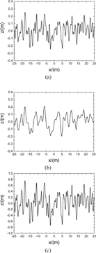
Figure 1: Geometric model of rough surface: (a) h = 0.1 m, l = 0.5 m, (b) h = 0.1 m, l = 1.0 m, (c) h = 0.3 m, l = 0.5 m, and (d) h = 0.1 m, l = 1.0 m.
The Monte Carlo method is generally used to randomly simulate a Gaussian rough surface with specified parameters. By changing the parameter values, Gaussian rough surfaces of different shapes can be obtained. Figure 1 shows the undulation of Gaussian rough surfaces generated under different parameters. It can be seen that a smaller correlation length and a larger root-mean-square height will lead to a steeper and more complex surface, making the surface rougher.
IV. ALGORITHM MODEL AND VALIDATION ANALYSIS
A. Coupled iterative integral equation
In reality, rough surfaces and targets do not exist independently but exist in the same space and interact with each other. Similarly, the electromagnetic scattering coupling phenomenon between rough surfaces and targets is the main factor affecting their composite electromagnetic scattering characteristics. Therefore, we have established an integral equation coupling rough surfaces and targets and solved it iteratively until convergence. The composite scattering schematic is shown in Fig. 2.
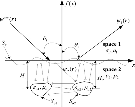
Figure 2: Composite scattering model for rough surfaces and targets.
Space 1 is the atmosphere, and its dielectric constant and magnetic permeability are , and. Space 2 is the dielectric rough surface, and its dielectric constant and magnetic permeability are , and . The depth of target 1 is H, the depth of target 2 is H, and the distance between them is L. The dielectric constant and magnetic permeability are and , respectively.
If the rough surface and the target are treated as a whole, the surface integral equation when the conical incident wave is irradiated onto the scattering model is
| (7) |
| (8) |
| (9) | |||
| (10) |
where denotes the wave functions in medium 1 and medium 2, respectively, and denotes the wave function in medium target 1 and medium target 2, respectively. The Green’s function in the medium , and the Green’s function in the target .
The boundary conditions for the above system of equations are
| (11) |
| (12) |
| (13) |
Then the MOM is used to discretize the above integral equation, so the matrix equation can be obtained as follows:
| (14) |
where denotes the conical incident wave on the rough surface. A, B, C, D are the rough surface matrices, K, L, P, Q are the target 1 matrices, V, W, X, Y are the target 2 matrices, E, F are the scattering contributions from target 1 to the rough surface, G, H are the scattering contributions from target 2 to the rough surface, I, J are the scattering contributions from the rough surface to the target 1, R, S are the scattering contributions from the rough surface to the target 2, M, N are the scattering contributions from target 2 to the target 1, and T, U are the scattering contributions from target 1 to target 2. For the specific values of each parameter, please refer to the literature [38], which is not repeated here to save space.
Considering the coupling effect between the rough surface and the targets, as well as between the targets, the coupled iterative solution of the above equations is required, and the set of iterative equations are
| (15) |
| (16) |
| (17) |
| (18) | |||
| (19) |
| (20) |
I is used as a criterion to determine whether the equation converges or not, and the convergence condition is
| (21) |
If the above equation is solved directly, too many unknowns will lead to low solution efficiency, which is unacceptable in practical applications, so a suitable algorithm needs to be used to accelerate the solution process.
The core of the solution of the banded matrix iterative approach canonical grid - conjugate gradient (BMIA/CAG-CMG) method is to decompose the original matrix equation into near-field matrix and far-field matrix by the strong/weak correlation distances, the original matrix is decomposed into matrices with Band and Toeplitz characteristics, and then CMG is used to solve the matrix equations, and in the iterative process, the matrix vector product is calculated quickly by using the FFT, thus speeding up the computation. The next section focuses on the BMIA/CAG-CMG algorithm.
B. Banded matrix iterative approach canonical grid – conjugate gradient method
Let the distance between the field point and the source point on the rough surface be and the strong/weak correlation distance be r, so the surface integral equation for the rough surface can be decomposed into a strong acting region and a weak acting region as follows:
| (22) | |||
| (23) |
The left parts of the above equations are the strong correlation matrix(band matrix) and the right parts are the weak correlation matrix. Therefore, according to the BMIA/CAG algorithm, the above set of equations can be transformed into the strong/weak correlation matrix equations as follows:
| (24) | |||
| (25) |
where ,,,,, and denote the strong and weak matrices of the free space and medium space, respectively.
For the region of , that belongs to the weak correlation matrix calculation region, which is very computationally intensive, and if calculated directly will greatly reduce the computational efficiency. Therefore, the weak correlation matrix is considered to be processed by CAG, and then the FFT can be used for fast calculation, so that:
| (26) |
The expression of the strong and weak correlation matrix equations become
| (27) | |||
| (28) |
The above matrix can be solved by the iterative method, whose n-th order iterative equation is
| (29) | |||
| (30) | |||
| (31) |
Its initial value is:
| (32) | |||
| (33) |
The iterative calculation ends when .
To handle the weakly correlated matrices in the iterative equation, the CAG method is required due to the large computational load. The method expands the weak matrix to Taylor series along the x-axis and represents the product of the weak matrix with vector as a product of several Toeplitz matrices and a vector. Then, the FFT algorithm is utilized for the quick computation of the matrix-vector product. This process allows us to effectively calculate weakly correlated matrices and avoid the issue of excessive computational load. The specific calculation process is as follows.
The elements y of each row in the weak correlation matrix can be expressed as
| (34) |
Its Taylor series expansion takes the form of
| (35) |
where denotes the l-th coefficient of the Taylor series expansion, Nis the total number of terms of the Taylor series expansion, and . Its first three coefficients are
| (36) | |||
| (37) | |||
| (38) |
It can be observed from the formula that when , each term in y is equivalent to the product of a Toeplitz matrix and a column vector, which makes it suitable for fast computation using FFT.
C. Validation of algorithm
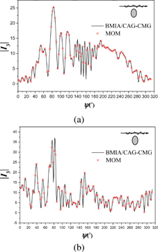
Figure 3: Target surface current: (a) TE incident wave and (b) TM incident wave.
The correctness of the algorithm proposed in this article needs to be verified before carrying out example calculations. We take an infinitely long cylindrical target with radius located beneath the rough medium at point as an example and analyze the composite electromagnetic scattering problem using two different methods, namely the BMIA/CAG-CMG-MoM method and the MoM method. We present the target surface current distribution obtained using different methods in Fig. 3, and their composite scattering coefficients are calculated and plotted in Fig. 4. Considering practical situations, we also introduce an incident wave with an incident angle of and select different parameter settings, including rough surface length , root mean square height , correlation length , and incident wave frequency f =1.2GHz. By comparing the results of the two methods, we find that they are consistent, indicating that the algorithm proposed in this article is correct. In addition, the time consumed by the two methods is listed in Table 1, which visually demonstrates the significant advantage of the proposed method in computational efficiency.
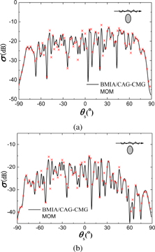
Figure 4: Composite scattering coefficients: (a) TE incident wave and (b) TM incident wave.
Table 1: Time consumption comparison
| Method | BMIA/CAG-CMG | MoM |
| Time | 279 s | 3721 s |
| BMIA/CAG-CMG is more than thirteen times faster than MoM | ||
V. CALCULATION RESULTS AND ANALYSIS
In this section, we have carried out detailed studies and analyses on several computational examples based on the proposed BMIA/CAG-CMG-MoM mutual coupling iteration algorithm. By simulating these examples, we have focused on the influence of the target on the scattering field of the rough surface when the relative permittivity of the rough surface, the distance between the target and the rough surface, the spacing between two targets, and the dielectric constant of the target change. The simulation results show that the proposed algorithm has good stability and computational accuracy when dealing with the above situations, and it has good reference value for studying the electromagnetic scattering characteristics of targets in complex backgrounds. At the same time, these analysis results provide valuable insights for further optimization and improvement of the BMIA/CAG-CMG-MoM mutual coupling iterative algorithm and may have guiding significance for future handling of similar problems.
A. The impact of rough surface dielectric constant on compound scattering characteristics
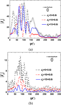
Figure 5: The surface current of the cylinder beneath the rough dielectric surface: (a) TE incident wave and (b) TM incident wave.
In Figs. 5 and 6, we conducted a comparative study on the surface currents and scattering coefficients of cylindrical targets under different rough surface relative permittivities. First, we set three different relative permittivities (5,0.6i), (10,0.6i), and (15,0.6i), keeping other parameters unchanged. In these three cases, we observed that the induced surface currents and scattering coefficients of the target increase with the increase of relative permittivities.
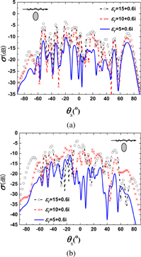
Figure 6: The composite scattering coefficient of the rough dielectric surface and the cylinder: (a) TE incident wave and (b) TM incident wave.
To analyze this phenomenon in more depth, we further explored the impact of the rough surface relative permittivity on the target surface current. The higher the rough surface relative permittivity, the stronger the transmission of the dielectric, which in turn makes the excitation of the target stronger. This feature results in larger induced surface currents and better thermal conductivity when the relative permittivity is high.
At the same time, the scattering coefficient of the rough surface also increases with the increase of relative permittivity. This is because the scattering coefficient is affected by multiple reflections and interference of waves between rough and smooth surfaces. When the relative permittivity is high, the multiple reflection and interference effects become more apparent, leading to an increase in the scattering coefficient.
Further analysis suggests that this phenomenon is closely related to the transmission of the dielectric and the multiple reflection and interference effects of the waves. Therefore, in practical applications, we need to consider these factors in order to more accurately assess and predict the scattering characteristics of the target.
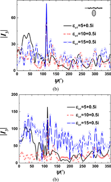
Figure 7: The impact of changes in target 1’s dielectric constant on its own surface current: (a) TE incident wave and (b) TM incident wave.
B. The effect of changes in the target’s dielectric constant on composite electromagnetic scattering properties
Figures 7, 8, and 9 show the changes in the surface currents and composite scattering coefficients of dielectric target 1 and dielectric target 2 when the dielectric constant of dielectric target 1 changes, respectively. We used a rough surface with a relative dielectric constant of and set the radii of the two targets to , the depths to, and the distance between them to . In the calculation process, we took three different dielectric constants,, and as the dielectric constant of dielectric target 1, and the other parameters were consistent with previous settings.
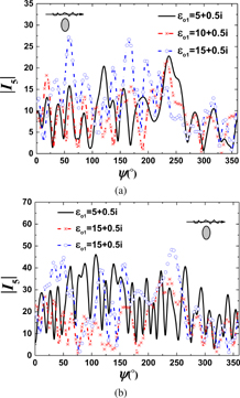
Figure 8: The impact of changes in target 1’s dielectric constant on the surface current of target 2: (a) TE incident wave and (b) TM incident wave.
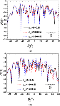
Figure 9: The impact of changes in the target’s dielectric constant on the scattering coefficient: (a) TE incident wave and (b) TM incident wave.
In this study, we observed some interesting phenomena regarding how the target’s dielectric properties affect the overall scattering characteristics. In particular, when the real part of the dielectric constant of target 1 is large, we found a significant increase in the induced current on the target surface, and the scattering effect of the rough surface became more pronounced. These observations strongly indicate that the dielectric properties of the target play a crucial role in its scattering characteristics. Therefore, it is essential to have a deep understanding and accurate prediction of the target’s dielectric properties when analyzing or studying issues involving electromagnetic wave propagation and interaction.
In addition, we noticed in the experiment that the surface current of target 2 was affected by the changes in the dielectric constant of target 1. This phenomenon reveals the mutual influence between the two targets, indicating that their coupling effect cannot be ignored. In the study of electromagnetic scattering problems, this coupling effect may cause certain prediction and estimation biases in practical applications. To avoid this situation, researchers need to fully consider and quantify the interactions between targets. Otherwise, neglecting the coupling effect between targets may lead to significant errors in the prediction and estimation of scattering characteristics, thereby affecting the accuracy and practicality of the model.
For practical applications, such as radar systems and communication systems, it is crucial to improve the accuracy of predicting and estimating scattering characteristics. The accuracy of prediction not only affects the effectiveness of applications but also affects the overall performance of the system. Therefore, considering the dielectric properties of targets and coupling effects is essential for studying electromagnetic wave propagation-related issues in practical applications.
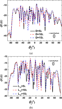
Figure 10: The influence of the distance between two targets on the composite electromagnetic scattering characteristics: (a) TE incident wave and (b) TM incident wave.
C. The influence of the distance between two targets on the composite electromagnetic scattering characteristics
In Fig. 10, we observe that as the distance between the two targets gradually decreases, the coupling effect between them gradually strengthens. This coupling effect leads to an increase in the induced current on the target surface, which in turn significantly enhances the total scattering of the targets on the rough surface. Specifically, the smaller the distance between the two targets, the more intense their interaction, resulting in a more pronounced scattering phenomenon on the rough surface.
In addition, the total scattering of the rough surface is also affected by the distance between the targets. When the two targets are closer together, the total scattering of the rough surface increases due to the enhanced coupling effect. This indicates that in practical applications such as radar detection systems, attention should be paid to this phenomenon.
In summary, the distance between targets has a significant impact on both the coupling effect between the two targets and the scattering on the rough surface. As the distance between the targets decreases, the mutual coupling between the targets becomes more prominent, leading to an increase in the scattering of the targets on the rough surface and the total scattering of the rough surface. Therefore, in-depth study of this phenomenon is of great importance for improving the detection accuracy in practical applications.
VI. CONCLUSION
In this paper, we propose a new fast iterative algorithm for investigating the electromagnetic scattering characteristics of a Gaussian rough surface and multiple targets below. We adopt the BMIA/CAG-CMG algorithm to improve computation efficiency and observe the effects of the dielectric properties of the rough surface and targets, as well as target spacing, on surface currents and composite scattering through simulation experiments. It is worth noting that we find that, under the same incident conditions, the higher the relative permittivity, the stronger the dielectric’s transmission rate and target excitation, leading to an increase in scattering coefficients, which is consistent with ourexpectations.
In addition, we can also see that the smaller the target spacing, the stronger the interaction between them, resulting in more severe scattering on the rough surface. Ultimately, we reveal the interactive mechanism between two targets, providing valuable ideas and references for further understanding and studying composite scattering characteristics. In summary, our research results provide new insights and ideas for electromagnetic scattering theory and offer useful references for the application of electromagnetic scattering problems in related fields.
Next, we can explore more factors influencing electromagnetic scattering and further improve the algorithm’s computation efficiency and accuracy. Meanwhile, we can also study the scattering characteristics of rough surfaces with different shapes and materials, as well as the electromagnetic scattering behavior of targets at different positions and directions, and so on. These studies will help us to understand electromagnetic scattering phenomena more deeply and provide more effective solutions for practical applications.
ACKNOWLEDGEMENT
This work was supported by Jiangxi Provincial Department of Education Science and Technology Project grant under GJJ2201716.
REFERENCES
[1] Q. K. Wang, C. M. Tong, X. M. Li, Y. J. Wang, Z. L. Wang, and T. Wang, “Composite electromagnetic scattering and high-resolution SAR imaging of multiple targets above rough surface,” Remote Sensing, vol. 14, no. 12, 2022.
[2] J. Chen, M. Zhu, M. Wang, S. Li, and X. Li, “A Hybrid MoM-PO method combining ACA technique for electromagnetic scattering from target above a rough surface,” Applied Computational Electromagnetics Society (ACES) Journal, vol. 29, no. 4, 2014.
[3] L. Guan, J. E. Wang, X. Chen, D. H. Cai, and C. Z. Dong, “Electromagnetic scattering analysis of large-area vegetation based on multilevel periodic fast multipole algorithm,” Engineering Analysis with Boundary Elements, vol. 147, pp. 1-8, 2023.
[4] A. V. Setukha, S. L. Stavtsev, and R. M. Tret’yakova, “Application of mosaic-skeleton approximations of matrices in the physical optics method for electromagnetic scattering problems,” Computational Mathematics and Mathematical Physics, vol. 62, no. 9, pp. 154-165, 2022.
[5] X. M. Sun, “Influence evaluation of UAV inlet on electromagnetic scattering and time-frequency characteristics,” Journal of Physics: Conference Series, vol. 1971, no. 1, pp. 1-6, 2021.
[6] Y. Liang and L. X. Guo, “A study of composite scattering characteristics of movable/rotatable targets and a rough sea surface using an efficient numerical algorithm,” IEEE Journal of Oceanic Engineering, vol. 46, no. 4, pp. 1412-1425,2021.
[7] D. Novák, L. Gregor, and J. Veselý, “Capability of a ground-based passive surveillance system to detect and track spaceborne SAR in LEO orbits,” Remote Sensing, vol. 14, no. 18, 2022.
[8] Y. C. Liang, Q. Z. Yang, Y. Q. Shi, J. Bai, and Q. Lin, “Numerical simulation and experimental study of ISAR imaging of spherical convergent flap nozzle,” Applied Computational Electromagnetics Society (ACES) Journal, vol. 35, no. 4, 2020.
[9] L. M. Madsen, T. Bording, D. Grombacher, N. Foged, N. Foley, H. A. Dugan, P. T. Doran, J. Mikucki, S. Tulaczyk, and E. Auken, “Comparison of ground-based and airborne transient electromagnetic methods for mapping glacial and permafrost environments: Cases from McMurdo Dry Valleys, Antarctica,” Cold Regions Science and Technology, vol. 199, 2022.
[10] J. He, Z. Xing, Q. Wang, F. Wu, and F. Lu, “A study on the diffraction correction prediction of electromagnetic field intensity based on the method of estimating aerial access network signal,” Wireless Commun. and Mobile Computing, vol. 2021, 2021.
[11] D. Zhang, C. Liao, J. Feng, X. Deng, and Y. Cheng, “Modeling of electromagnetic wave coupling to thin-wire structures in terrain environments using hybrid PE/TPIE method,” Int. J. Antennas and Propagation, vol. 2019, 2019.
[12] X. Deng, C. Gu, and Y. Zhou, “Electromagnetic scattering by arbitrary shaped three-dimensional conducting objects covered with electromagnetic anisotropic materials,” Applied Computational Electromagnetics Society (ACES) Journal, vol. 26, no. 11, 2011.
[13] C. Yang, and L. Wu, “GPU-Based volume rendering for 3D electromagnetic environment on virtual globe,” Int. J. Image Graphics and Signal Processing, vol. 2, no. 1, 2010.
[14] M. V. Grafkina, E. Y. Sviridova, and E. R. Veliyeva, “Environmental monitoring of electromagnetic fields in residential areas,” IOP Conference Series: Earth and Environmental Science, vol. 688, no. 1, 2021.
[15] X. L. Chen, C. Gu, X. Q. Deng, B. Z. Xu, Z. Li, and Z. Niu, “A hybrid ACA-FDM for electromagnetic scattering from PEC targets,” Applied Computational Electromagnetics Society (ACES) Journal, vol. 27, no. 12, 2012.
[16] J. Chen, S. Li, and Y. Song, “Analysis of electromagnetic scattering problems by means of a VSIE-ODDM-MLFMA method,” Applied Computational Electromagnetics Society (ACES) Journal, vol. 27, no. 8, 2012.
[17] O. Korostynska, A. Mason, M. Ortoneda-Pedrola, and A. Al-Shamma’a, “Electromagnetic wave sensing of NO3 and COD concentrations for real-time environmental and industrial monitoring,” Sensors & Actuators: B. Chemical, vol. 198, 2014.
[18] E. Petraki, D. Nikolopoulos, A. Fotopoulos, D. Panagiotaras, G. Koulouras, A. Zisos, C. Nomicos, A. Louizi, and J. Stonham, “Self-organised critical features in soil radon and MHz electromagnetic disturbances: Results from environmental monitoring in Greece,” Applied Radiation and Isotopes, vol. 72, 2013.
[19] M. Tkalec, K. Malarić, and B. Pevalek-Kozlina, “Influence of 400, 900, and 1900 MHz electromagnetic fields on Lemna minor growth and peroxidase activity,” Bioelectromagnetics, vol. 26, no. 3,2005.
[20] Y. Zeng, G. Zeng, L. Huang, X. Li, J. Guo, and J. Wang, “Application of transient electromagnetic method with multi-radiation field sources in deep edge mineral resources exploration,” Acta Geologica Sinica - English Edition, vol. 95, no. S1, 2021.
[21] H. Tan, F. Ling, Z. Guo, J. Li, and J. Liu, “Application of a wide-field electromagnetic method for hot dry rock exploration: A Case Study in the Gonghe Basin, Qinghai, China,” Minerals, vol. 11, no. 10, 2021.
[22] H. Wei, T. Qi, G. Feng, and H. Jiang, “Comparative Research on Noise Reduction of Transient Electromagnetic Signals Based on Empirical Mode Decomposition and Variational Mode Decomposition,” Radio Science, vol. 56, no. 10, 2021.
[23] M. Shen, “Launching system of helicopter aviation transient electromagnetic system,” Journal of Physics: Conference Series, vol. 1802, no. 2, 2021.
[24] G. Xue, L. Zhang, N. Zhou, and W. Chen, “Developments measurements of TEM sounding in China,” Geological Journal, vol. 55, no. 3, 2020.
[25] V. A. Kulikov, A. E. Kaminsky, and A. G. Yakovlev, “Combined 2D inversion of electrotomographic and audio-magnetotellurgic sounding data to solve mining problems,” Zapiski Gornogo Instituta, vol. 223, no. 1, 2017.
[26] G. X. Zou, C. M. Tong, J. Zhu, H. L. Sun, and P. Peng, “Study on composite electromagnetic scattering characteristics of low-altitude target above valley composite rough surface using hybrid SBR-EEC method,” IEEE Access, vol. 8, pp. 152493-152502, 2020.
[27] H. L. Sun, C. M. Tong, and P. Peng, “Improved hybrid FEM/MOM combining MLFMA for composite electromagnetic scattering,” Electromagnetics, vol. 37, no. 8, pp. 479-492, 2017.
[28] Y. Liang, L. X. Guo, Z. S. Wu, and Q. H. Liu, “A study of composite electromagnetic scattering from an object near a rough sea surface using an efficient numerical algorithm,” IEEE Antennas and Wireless Propagation Letters, vol. 15, pp. 828-831, 2016.
[29] J. Li, L. X. Guo, and S. Chai, “Composite electromagnetic scattering from an object situated above rough surface,” Applied Optics, vol. 53, no. 35, pp. 8295-8304, 2014.
[30] X. M. Zhu, and X. C. Ren, “Study on composite electromagnetic scattering from 1D weierstrass fractal land surface with buried target using FDTD,” Applied Mechanics and Materials, vol. 539, pp. 539-543, June 2014.
[31] M. L. Zhao, J. H. He, and N. Zhu, “Fast high-order algorithms for electromagnetic scattering problem from finite array of cavities in te case with high wave numbers,” Mathematics, vol. 10, no. 16, pp. 1-20, 2022.
[32] J. M. Wu, X. B. He, B. Wei, and X. L. Li, “Fast parallel FDFD algorithm for solving electromagnetic scattering problems,” Journal of Electrical and Electronic Engineering, vol. 9, no. 6, pp. 455-460, 2021.
[33] R. Q. Liu, X. W. Huang, Y. L. Du, M. L. Yang, and X. Q. Sheng, “Massively parallel discontinuous galerkin surface integral equation method for solving large-scale electromagnetic scattering problems,” IEEE Transactions on Antennas and Propagation, vol. 69, no. 9, pp. 5049-5059, 2021.
[34] A. L. Deng, and L. M. Zhang, “Direct solution of the volume integral equation for electromagnetic scattering from dielectric objects with negative permittivity,” Journal of the Optical Society of America. A, Optics, Image Science, and Vision, vol. 38, no. 7, pp. 1031-1038, 2021.
[35] W. Kong, X. Yang, F. Zhou, J. Xie, C. Chen, N. Li, and W. Yang, “Fast analysis of broadband electromagnetic scattering characteristics of electrically large targets using precorrected fast fourier transform algorithm based on near field matrix interpolation method,” Applied Computational Electromagnetics Society (ACES) Journal, vol. 36, no. 7, pp. 769-776, 2021.
[36] L. Tsang, J. A. Kong, K. H. Ding, and C. O. Ao, “Scattering of electromagnetic waves: Numerical simulations,” New York: Wiley Interscience, 2001.
[37] W. H. Press, S. A. Teukolsky, and W. T. Vetterling, “Numerical Recipes in FORTRAN,” New York: Cambridge University Press, 1992.
[38] R. F. Harrington, “Field computation by moment method,” New York: MacMillan, 1968.
BIOGRAPHIES

Lilan Lei was born in Jiangxi, China. She received the bachelor’s and master’s degrees from Jiangxi Normal University, Jiangxi, China, in 2002 and 2009, respectively. Her research interests include computer applications and computer communication.
ACES JOURNAL, Vol. 38, No. 8, 575–586
doi: 10.13052/2023.ACES.J.380804
© 2023 River Publishers