Design of Wideband 88 Butler Matrix using Composite Right/Left-handed Transmission Line for Multi-mode OAM Generation
Yan Zhang, Haoran Ye, Jialin Zhang, Xurui Zhang, and Shanwei Lü
1School of Electronic Information Engineering
Beihang University, Beijing, China
yanzhang@buaa.edu.cn, yehaoran@buaa.edu.cn, sy1902127@163.com,zy2202328@buaa.edu.cn, lueshw@buaa.edu.cn
2Shenzhen Institute of Beihang University
Shenzhen, China
Submitted On: August 28, 2023; Accepted On: April 28, 2024
ABSTRACT
In this paper, a wideband Butler matrix for the uniform circular array antenna (UCA) generating multi-mode orbital angular momentum (OAM) vortex wave is designed. Firstly, the novel network topology of a Butler matrix is proposed. For the purpose of design and optimization convenience, the 88 Butler matrix is separated into two different sub 44 Butler matrix modules and one connection-output module. Then several wideband microwave components used in a Butler matrix, such as 3 dB directional coupler and stable phase shifter with composite right/left-handed (CRLH) transmission line, are designed. To demonstrate the effectiveness of the design process, a Butler matrix working in 5-7 GHz is designed and fabricated. It is found that the simulation results are in good agreement with the measured data. The constant amplitude distribution and progressive phase differences of 45, 90 between the output ports are observed, hence the 1, 2 mode OAM waves can be generated by the proposed Butler matrix.
Index Terms: Butler matrix, CRLH transmission line, multi-mode OAM, wideband.
I. INTRODUCTION
Expected in the 2030s, 6-generation (6G) communication planning has begun. Compared with 5G, higher capacity, higher data rates, and lower latency are required by the 6G communication system. A possible way to increase data rate of wireless communication is to use orbital angular momentum (OAM) vortex waves instead of traditional plane waves [1–4]. This spatial reuse of different OAM modes could improve greatly the channel capacity [5–7].
Compared with other methods of generating OAM waves [8–12], uniform circular array antenna (UCA) support the generation of a variety of OAM modes [13–15], and its feed status can be adjusted to generate OAM of various modes flexibly. UCA can be fed by beamforming network (BFN) which have economical and efficient advantages to generate OAM waves with connection to the UCA element. BFNs such as a Butler matrix [16–17] are usually composed of coupler, crossover, and phase shifter. In order to obtain a high quality OAM wave, the design of the microwave components of a Butler matrix is import and difficult to realize in wideband.
With a conventional Butler matrix with one layer transmission line it is difficult to realize a stable phase shift for wideband application [18]. In order to realize wideband performance, a multi-layer coupling structure is discussed [19, 20]. For the design of the phase shifter, a composite right/left-handed (CRLH) transmission line [21, 22] is applied to the phase shifter to obtain larger phase shift values with necessary compact structure. To simplify the topology of a Butler matrix, fewer phase shifters are desired for generating necessary OAM modes. A simplified Butler matrix topology is necessary but relevant research is rare.
In this paper, a wideband 88 Butler matrix for generating 1/2 modes OAM waves is designed. For some key microwave components, 3 dB directional couplers and phase shifters with the phase value of 45, 0, and 90 are designed by wideband structure with the CRLH transmission line in order to realize stable phase shift.
II. TOPOLOGY OF A BUTLER MATRIX
For OAM application, the UCA element is fed by BFN with equal amplitude and progressive phase difference [23]. In order to generate an OAM beam of 1/2 mode by feeding eight-element antenna array, an equal amplitude distribution with phase differences of 45 and 90 are required.
Firstly, the sub Butler matrix module 1 and 2 is proposed to realize consistent phase difference between the four output ports. Then, the sub Butler matrix modules are connected by connection-output modules to obtain consistent phase difference of eight outputs. The sub Butler matrix module 1 based on 0/45 phase shifter and sub Butler matrix module 2 based on 90 phase shifter are designed, as shown in Fig. 1.
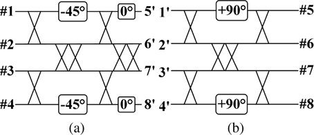
Figure 1: Topology of sub Butler matrix module: (a) sub Butler matrix module 1 and (b) sub Butler matrix module 2.
As shown in Fig. 1, port #1-8 on the left side are input ports and port #1’-8’ on the right side are output ports. The sub Butler matrix modules 1 and 2 can realize equal phase differences output of 45, 45, 90, and 90 by the excitation of port 1, 4, 5, and 8, respectively. The connection-output module is shown in Fig. 2.
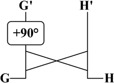
Figure 2: Connection-output module.
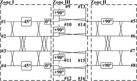
Figure 3: Topology of an 88 Butler matrix.
As shown in Fig. 2, four outputs of a sub Butler matrix module are connected to the input of a connection-output module in sequence to obtain eight outputs which have 180 phase difference between those two outputs, ports G’ and H’. The entire 88 Butler matrix network is shown in Fig. 3.
As shown in Fig. 3, the input ports are located on the outside and the transmission lines of the output ports do not overlap with each other. In this design, only 0/45/90 phase shifters are needed, so the design complexity of the wideband phase shifter is reduced. For sub module 1 (Fig. 3 zone I), the 45 phase shifter and cross coupler are used to realize 45, 45 output phase differences by excitation of ports 1 and 4, respectively. For sub module 2 (Fig. 3 zone II), the 90 phase shifter and cross coupler are used to realize 90, 90 output phase differences by excitation of ports 5 and 8, respectively. In order to generate +1 mode OAM, the excitation of port 4 could realize 45 phase difference distributions of 90, 45, 0 and 45. The phase distributions of 90, 45, 0, 45, 90, 135, 180, and 225 can be generated by the connection-output module (Fig. 1 zone III) because of the 180 phase difference between the two output ports of the connection-output module. The phase distribution of 1 mode OAM can be realized by the excitation of port 1, and the excitation of ports 5 and 8 can realize the phase distribution of 2 mode and +2 mode, respectively.
The detailed phase distribution of the Butler matrix is listed in the Table 1 for 1, 2 mode with phase difference of 45, +45, 90, and +90. The phase of each input port is zero, which satisfies the condition of unequal phase differences with different excitations of input ports. Compared with the conventional 88 Butler matrix exciting eight OAM modes, the proposed Butler matrix could provide the necessary modes with fewer phase shifters.
Table 1: Phase distribution of 88 Butler matrix
| Mode | 1 | 1 | 2 | 2 | |
| Input Port | 1 | 4 | 5 | 8 | |
| Output Port | P9 | 45 | 90 | 90 | 180 |
| P10 | 0 | 45 | 0 | 90 | |
| P11 | 45 | 0 | 90 | 0 | |
| P12 | 90 | 45 | 180 | 90 | |
| P13 | 135 | 90 | 270 | 180 | |
| P14 | 180 | 135 | 0 | 270 | |
| P15 | 225 | 180 | 90 | 0 | |
| P16 | 270 | 225 | 180 | 90 |
III. DESIGN OF WIDEBAND COMPONENT
The performance of each component using an 88 Butler matrix would affect the wideband stability of the whole network significantly. So, the accurate design and balance optimization of 3 dB directional coupler and 45/0/90 phase shifter are necessary. Firstly, a wideband 3 dB coupler is designed. Then, a 45 phase shifter is obtained by adding a rectangular patch into the 3 dB coupler structure. Also, a transverse slot line is introduced into the rectangular patch to realize a 0 phase shifter. Finally, two 45 phase shifters based on CRLH transmission line are applied to the 0 phase shifter to realize a 90 phase shifter.
A.3 dB directional coupler and 45/0 phase shifter
The 3 dB directional coupler is designed, as shown in Fig. 4.
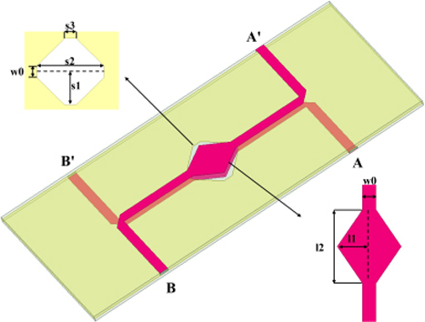
Figure 4: 3 dB directional coupler (s1 4.78, s2 9.5, w0 1.61, s3 1.66, l1 3.8, l2 8.75 unit mm).
As shown in Fig. 4, the 3 dB directional coupler consists of two pieces of substrate (h 0.6 mm, =). The top metal layer includes ports B and A’. The bottom metal layer is similar to the top layer, but the ports here are ports A and B’. The two coupling patches and the slot are given a diamond shape in order to avoid the discontinuity of the structure and reduce edge capacitance. The impedance of input and output ports is 50 to connect with RF lines. The simulation results are shown in Fig. 5.
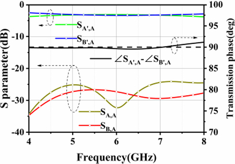
Figure 5: Simulation results of 3 dB directional coupler.
As shown in Fig. 5, the simulation results show that the amplitude balance is 3.250.15 dB and the phase balance is 900.5 in the operating frequency range. The isolations of SA,A and SB,A are less than 24 dB which indicates that the coupling between the two input ports is low and has little effect with the situation of multi-ports excitation. The 45 phase shifter is designed based on the structure of the 3 dB directional coupler. The structure of the 45 phase shifter is shown in Fig. 6.
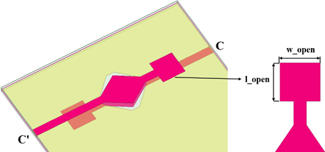
Figure 6: 45 phase shifter (l_open 4.88, w_open 5.1, unit mm).
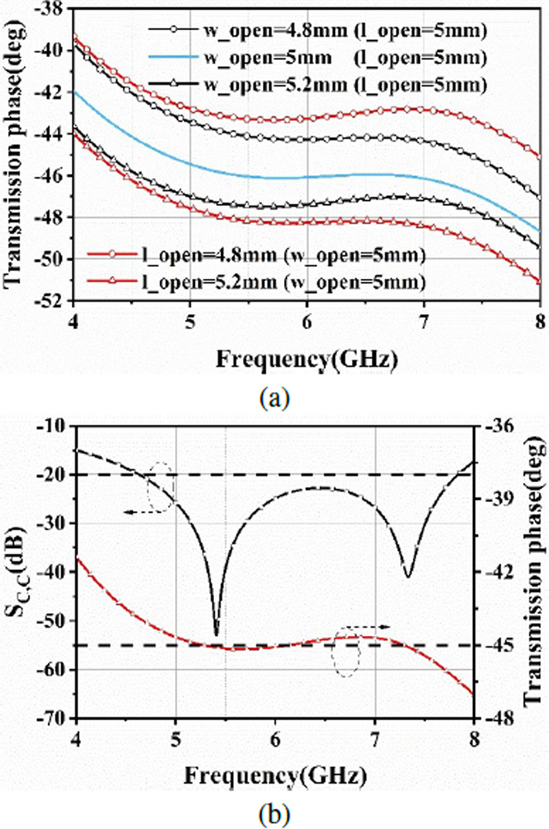
Figure 7: Simulation results of 45 phase shifter: (a) effect of w_open and l_open and (b) S parameter.
In order to obtain a wideband 45 phase shifter, a rectangular patch is applied as an open-circuit structure. The effect of width and length of the rectangle patch on the phase shift is investigated. The simulation results are shown in Fig. 7.
From Fig. 7, a stable phase shift of 450.3 can be observed. The 0 phase shifter is designed based on the structure of the 45 phase shifter, as shown in Fig. 8.
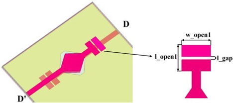
Figure 8: 0 phase shifter (l_open1 4.64, w_open1 5.2, l_gap 0.5, unit mm).
Based on the 45 phase shifter, a transverse slot line is introduced into the rectangle patch to realize the 0 phase shifter. The simulation results are shown in Fig. 9.
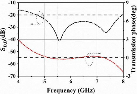
Figure 9: Simulation results of 0 phase shifter.
It can be seen from Fig. 9 that the phase difference between port D and port D’ is near to 0 and thus the 0 phase shifter is generated. The error of the 0 phase shifter is 0.25 with the frequency range of 5-7 GHz.
B. 45/90 phase shifter
By cascading the 0 phase shifter to two 45 phase shifters with the CRLH transmission line, a 90 phase shifter could be realized. Firstly, the 45 phase shifter is designed, as shown in Fig. 10.
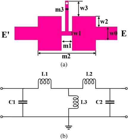
Figure 10: 45 phase shifter (a) model and (b) equivalent circuit (m1 1.3, m2 7.1, m3 0.4, w0 1.61, w1 0.5, w2 1.3, w3 1.9, unit mm).
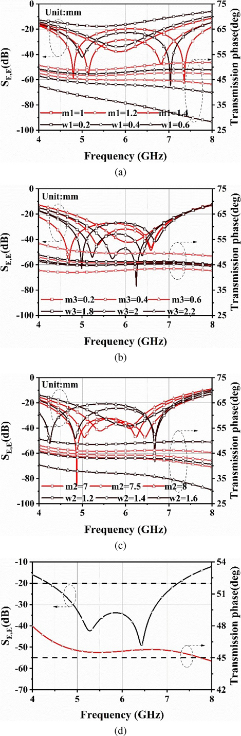
Figure 11: Simulation results of 45 phase shifter: (a) effect of series inductance, (b) effect of parallel inductance, (c) effect of parallel capacitors, and (d) optimized simulation results.
As shown in Fig. 10, the CRLH transmission composed of patch and microstrip line is simplified to the parallel inductors and series capacitors existing in the left-handed structure, so this shifter become miniaturized. The effect of the dimensions of CRLH transmission line structure on transmission parameter is investigated. The simulation results are shown in Fig. 11.
The series inductance, parallel inductance, and parallel capacitors have effect on both low-frequency resonance points and high-frequency resonance points. Bandwidth can be changed by adjusting the structure parameters. The simulation results show that the phase imbalance does not exceed 0.8 at 5-7 GHz. Wideband stable phase shift characteristics can be observed. The 90 phase shifter is designed based on the 45 phase shifter as shown in Fig. 12.
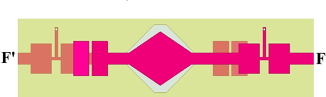
Figure 12: 90 phase shifter.
On the basis of the 0 phase shifter, the CRLH transmission line is connected at the input port and output port to obtain the 90 phase shifter structure. The simulation results are shown in Fig. 13.
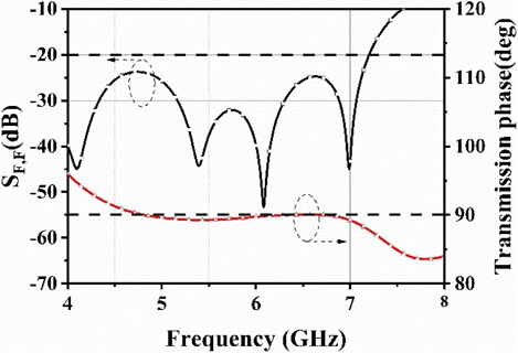
Figure 13: Simulation results of 90 phase shifter.
As shown in Fig. 13, the simulation results indicate that the phase shift value is 89.60.4. Hence, large and stable phase shift values can be achieved in the wide band, compared with a conventional phase shifter.
In general, the 3 dB coupler and 45/0/90 phase shifter are designed in sequence. The imbalance of the amplitude and phase shift are quite small for this component.
IV. SUB BUTLER MATRIX AND CONNECTION-OUTPUT MODULE
Based on the wideband components, a sub Butler matrix module and connection-output module could be obtained. The sub Butler matrix module is shown in Fig. 14.
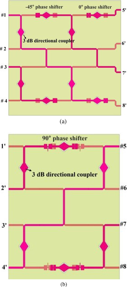
Figure 14: Sub Butler matrix module: (a) sub module 1 and (b) sub module 2.
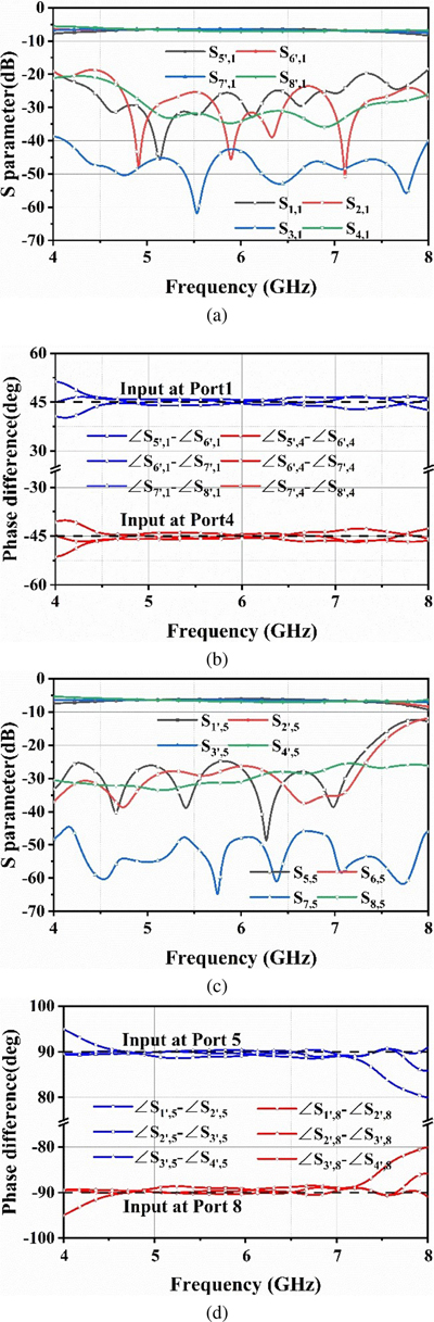
Figure 15: Simulation results of a sub Butler matrix module: (a) S, (b) output phase of sub Butler matrix module 1, (c) S, and (d) output phase of sub Butler matrix module 2.
Using the phase shifter and 3 dB directional coupler designed above, the sub Butler matrix module is constructed by connecting these components with a microstrip line in Fig. 14 corresponding to zones I and II in Fig. 3. The simulation results are shown in Fig. 15.
It can be seen from Fig. 15 that the amplitude imbalance of the output of sub Butler matrix modules 1 and 2 do not exceed 0.8 dB and 1.0 dB, respectively. The 45+1.6 and 901.5 phase differences can be obtained by excitation ports 1, 4, 5, and 8. In order to combine two 44 sub Butler matrix modules and output ports, the connection-output module corresponding to zone III in Fig. 3 is designed. The connection-output module is shown in Fig. 16.
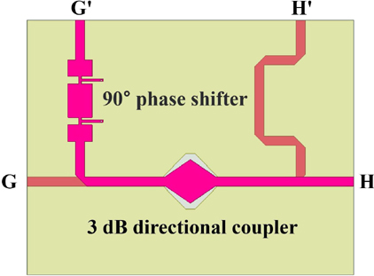
Figure 16: Connection-output module composed of 90 phase shifter and 3 dB directional coupler.
The simulation results are shown in Fig. 17.
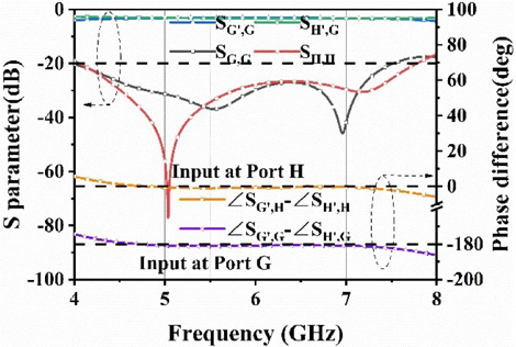
Figure 17: Simulation results of connection-output module.
As shown in Fig. 17, the simulation results indicate the reflection coefficient and isolation are less than 25 dB at 5-7 GHz. The amplitude balance of the output ports is 3.20.3 dB. The 1801.2 and 01.0 phase difference between ports G’ and H’ can be realized by the excitation of ports G and H, respectively.
V. RESULTS AND DISCUSSION
Based on the sub Butler matrix module and connection-output module, an 88 Butler matrix can be realized, as shown in Fig. 18.
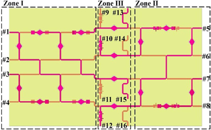
Figure 18: 88 Butler matrix.
Corresponding to the topology of Fig. 1, zone I and zone II are sub Butler matrix module 1 and module 2, respectively. These two sub Butler matrix modules are connected by the middle connection-output module, as shown in zone III. The phase distribution of 1, 2 OAM modes can be obtained from the 9-16 outputs by the excitation of ports 1, 4, 5, and 8, respectively. The simulation results are shown in Figs. 19 and 20.
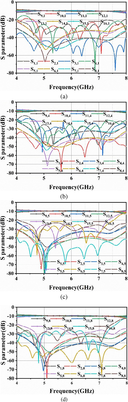
Figure 19: Simulation results of S parameters: (a) port 1, (b) port 4, (c) port 5, and (d) port 8.
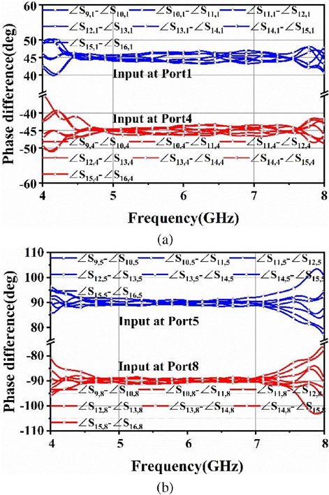
Figure 20: Simulation results of phase difference: (a) input at port 1 and port 4 and (b) input at port 5 and port 8.
The simulation results indicate that there is a similarity between ports 1 and 4, as well as between ports 5 and 8, due to the symmetry of the Butler matrix structure. It can be observed that the amplification is almost equal and phase distribution is consistent with theory results as shown in Table 1. The reflection coefficient of ports 1 and 5 and the isolations are less than 20 dB in 5-7 GHz. The transmission coefficients for input ports 1 and 5 is 9.90.6 dB and 9.70.5 dB, respectively. The phase balances by the excitation of ports 1 and 5 are 452.1 and 902.2, respectively. Quite good amplitude and phase stability can be observed in wideband.
In order to demonstrate the design work, two sub Butler matrix modules and a connection-output module are fabricated, as shown in Fig. 21.
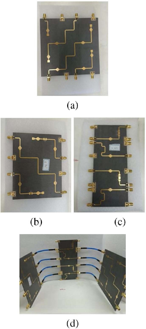
Figure 21: Photographs of the proposed Butler matrix: (a) sub Butler matrix module 1, (b) sub Butler matrix module 2, (c) connection-output module, and (d) whole Butler matrix.
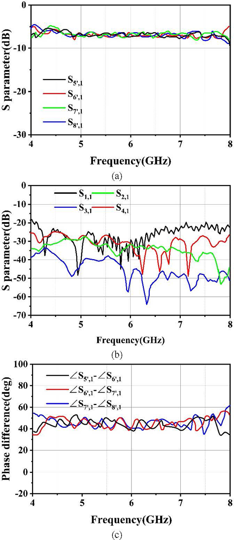
Figure 22: Measured results of sub Butler matrix module 1: (a) transmission coefficient, (b) reflection coefficient and isolation, and (c) phase difference of output.
A complete 88 Butler matrix structure can be obtained by connecting the output port of the sub Butler matrix module with input port of the connection-output module. The S parameters of these three modules and the 88 Butler matrix are measured. The measured results of the sub Butler matrix module 1 are shown inFig. 22.
As shown in Fig. 22, the amplitude imbalance of output of sub Butler matrix module 1 does not exceed 1.2 dB. The 455.6 phase difference can be obtained by excitation port 1. The measured results of sub Butler matrix module 2 are shown in Fig. 23.
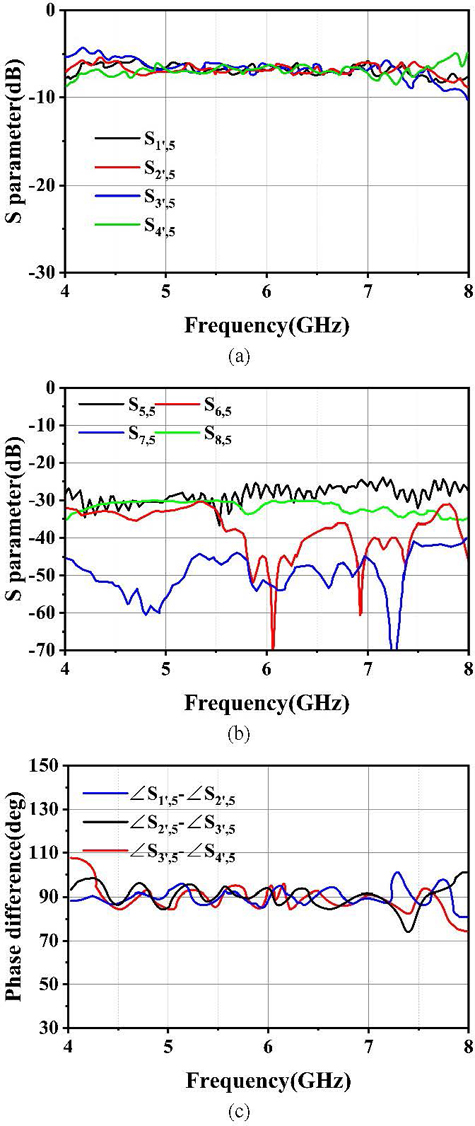
Figure 23: Measured results of sub Butler matrix module 2: (a) transmission coefficient, (b) reflection coefficient and isolation, and (c) phase difference of output.
As shown in Fig. 23, the amplitude imbalance of the output of sub Butler matrix module 2 does not exceed 1.4 dB. The 905.5 phase difference can be obtained by excitation port 5. The measured results of connection-output module are shown in Fig. 24.
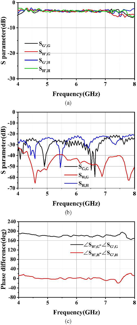
Figure 24: Measured results of connection-output module: (a) transmission coefficient, (b) reflection coefficient and isolation, and (c) phase difference of output.
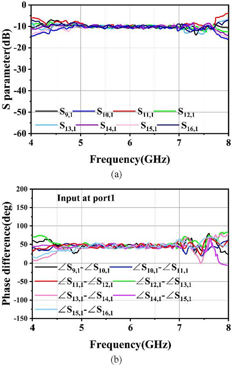
Figure 25: Measurement results for mode: (a) transmission coefficient and (b) phase difference of output.
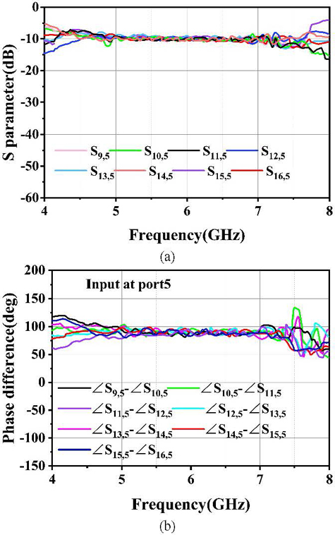
Figure 26: Measurement results for mode: (a) transmission coefficient and (b) phase difference of output.
As shown in Fig. 24, the amplitude and phase balance of connection-output module is 3.30.5 dB and 1805.2 in the operating frequency range. The measured results of the 88 Butler matrix is shown in Figs. 25 and 26.
From Figs. 25 and 26, it can be seen that the measured results are in good agreement with the simulation results. The amplitude and phase balance in the operating frequency range are 10.30.8 dB and 10.00.7 dB, 457.3 and 907.2 for 1 mode and 2 mode, respectively. The amplified and phase error between measured and simulation results is less than 0.5 dB and 5 in most frequencies. Compared with the existing designs of the Butler matrix listed in Table 2, the number of beams for beamforming Butler matrix and the number of OAM wave modes for OAM generate Butler matrix is also listed. The proposed work has the advantages of low insertion loss, small phase error, and wide bandwidth, which is very attractive in wideband OAM generation. Also, the modified topology of the Butler matrix needed fewer phase shifters to generate necessary OAM modes.
Table 2: Comparison with previews work
| Ref. | Freq.(GHz) | Insert Loss/Phase Error | Band-width | Return Loss/Isolation | Ports Num. | Beams/Modes Num. |
| [24] | 1.8 | dB/4 | 12% | 25 dB/20 dB | 44 | 4 Beams |
| [25] | 7.5 | 7 1 dB /7 | 10.7% | 10 dB/15 dB | 44 | 3 Modes |
| [26] | 2.2 | 10.12.2 dB/20.7 | 27% | 10 dB/10 dB | 88 | 8 Beams |
| [27] | 2.45 | 10 1 dB/10 | 8% | 15 dB/15 dB | 88 | 4 Modes |
| This work | 5-7 | 10.30.8 dB/7.3 | 33% | 15 dB/15 dB | 88 | 4 Modes |
VI. CONCLUSION
In this paper, a wideband 88 Butler matrix for generating 1/2 OAM modes is designed. Unlike the conventional 88 Butler matrix generating eight modes, this design requires fewer phase shifters to generate necessary modes OAM vortex wave. Wideband microwave components are designed, namely 3 dB directional coupler and 45/0/90 phase shifters based on CRLH transmission line. Two sub Butler matrix modules and a connection-output module are designed to form the 88 Butler matrix. This provides a design for generating multi-mode OAM waves with the advantages of simplified Butler matrix structure and stable transmission performance in the wide band. It is found that the measured results are in good agreement with simulation results. The quite small imbalance of amplitude and phase shift can be realized for different OAM modes.
ACKNOWLEDGMENT
This work was supported in part by the National Key Research and Development Program of China (2020YFB1807400), in part by the National Program on Key Basic Research Project of China (2019-JCJQ-ZD-067-00), and in part by the Shenzhen central government guidance local science and technology development fund under grant 2021Szvup081.
REFERENCES
[1] B. Thidé, H. Then, J. Sjöholm, K. Palmer, J. Bergman, T. D. Carozzi, Y. N. Istomin, N. H. Ibragimov, and R. Khamitova, “Utilization of photon orbital angular momentum in the low-frequency radio domain,” Physical Review Letters, vol. 99, no. 8, p. 087701, 2007.
[2] S. M. Mohammadi, L. K. S. Daldorff, K. Forozesh, B. Thidé, J. E. S. Bergman, B. Isham, R. Karlsson, and T. D. Carozzi, “Orbital angular momentum in radio: measurement methods,” Radio Science, vol. 45, no. 4, 2010.
[3] A. Papathanasopoulos and Y. Rahmat-Samii, “A review on orbital angular momentum (OAM) beams: Fundamental concepts, potential applications, and perspectives,” in 2021 XXXIVth General Assembly and Scientific Symposium of the International Union of Radio Science (URSI GASS), Rome, Italy, pp. 1-4, 2021.
[4] F. Tamburini, E. Mari, A. Sponselli, B. Thidé, A. Bianchini, and F. Romanato, “Encoding many channels on the same frequency through radio vorticity: first experimental test,” New Journal of Physics, vol. 14, no. 3, pp. 811-815, 2011.
[5] K. A. Opare, Y. Kuang, and J. J. Kponyo, “Mode combination in an ideal wireless OAM-MIMO multiplexing system,” IEEE Wireless Communications Letters, vol. 4, no. 4, pp. 449-452,Aug. 2015.
[6] Y. Ren, L. Li, G. Xie, Y. Yan, Y. Cao, H. Huang, N. Ahmed, Z. Zhao, P. Liao, C. Zhang, G. Caire, A. F. Molisch, M. Tur, and A. E. Willner, “Line-of-sight millimeter-wave communications using orbital angular momentum multiplexing combined with conventional spatial multiplexing,” IEEE Transactions on Wireless Communications, vol. 16, no. 5, pp. 3151-3161, May 2017.
[7] W. Cheng, H. Zhang, L. Liang, H. Jing, and Z. Li, “Orbital-angular-momentum embedded massive mimo: achieving multiplicative spectrum-efficiency for mmwave communications,” IEEE Access, vol. 6, pp. 2732-2745, 2018.
[8] Y. Yan, G. Xie, M. P. J. Lavery, H. Huang, N. Ahmed, C. Bao, Y. Ren, Y. Cao, L. Li, Z. Zhao, A. F. Molisch, M. Tur, M. J. Padgett, and A. E. Willner, “High-capacity millimetre-wave communications with orbital angular momentum multiplexing,” Nature Commun., vol. 5, pp. 1-9, Sep. 2014.
[9] F. Qin, J. Yi, W. Cheng, Y. Liu, H. Zhang, and S. Gao, “A high-gain shared aperture dual-band OAM antenna with parabolic reflector,” in Proc. 12th Eur. Conf. Antennas Propag. (EuCAP), London, pp. 8-11, 2018.
[10] L. Fang, H. Yao, and R. M. Henderson, “OAM antenna arrays at E-band,” in IEEE MTT-S Int. Microw. Symp. Dig., Honolulu, HI, pp. 658-661, June 2017.
[11] J. Liang and S. Zhang, “Orbital angular momentum (OAM) generation by cylinder dielectric resonator antenna for future wireless communications,” IEEE Access, vol. 4, pp. 9570-9574, 2016.
[12] B. Xu, C. Wu, Z. Wei, Y. Fan, and H. Li, “Generating an orbital-angular momentum beam with a metasurface of gradient reflective phase,” Opt. Mater. Exp., vol. 6, no. 12, p. 3940, 2016.
[13] H. Sasaki, Y. Yagi, T. Yamada, T. Semoto, and D. Lee, “Hybrid OAM multiplexing using Butler matrices toward over 100 Gbit/s wireless transmission,” 2020 IEEE Globecom Workshops, Taipei, Taiwan, pp. 1-5, 2020.
[14] P.-Y. Feng, S.-W. Qu, and S. Yang, “OAM-generating transmitarray antenna with circular phased array antenna feed,” IEEE Transactions on Antennas and Propagation, vol. 68, no. 6, pp. 4540-4548, June 2020.
[15] R. Chen, W.-X. Long, X. Wang, and L. Jiandong, “Multi-mode OAM radio waves: Generation, angle of arrival estimation and reception with UCAs,” IEEE Transactions on Wireless Communications, vol. 19, no. 10, pp. 6932-6947, Oct. 2020.
[16] J. Butler and R. Lowe, “Beam-forming matrix simplifies design of electronically scanned antenna,” Electron. Des., vol. 9, pp. 170-173, 1961.
[17] H. Moody, “The systematic design of the Butler matrix,” IEEE Trans. Antennas Propag., vol. 12, no. 6, pp. 786-788, 1964.
[18] Q. Sun, Y.-L. Ban, J.-W. Lian, and X.-F. Li, “A new array formation method for millimeter-wave transverse slot scanning array antenna,” in 2020 IEEE International Symposium on Antennas and Propagation and North American Radio Science Meeting, Montreal, QC, Canada, pp. 707-708,2020.
[19] I. Messaoudene, H. Youssouf, M. Bilal, M. Belazzoug, and S. Aidel, “Performance improvement of multilayer Butler matrix for UWB beamforming antenna,” Proc. Seminar Detection Syst. Archit. Technol.(DAT), pp. 1-4, 2017.
[20] A. A. M. Ali, N. J. G. Fonseca, F. Coccetti, and H. Aubert, “Design and implementation of two-layer compact wideband Butler matrices in SIW technology for Ku-band applications,” IEEE Trans. Antennas Propag., vol. 59, no. 2, pp. 503-512, Feb.2011.
[21] S. Lim, C. Caloz, and T. Itoh, “Metamaterial-based electronically controlled transmission-line structure as a novel leaky-wave antenna with tunable radiation angle and beamwidth,” IEEE Transactions on Microwave Theory and Techniques, vol. 52, no. 12, pp. 2678-2690, Dec. 2004.
[22] A. Karimbu Vallappil, M. K. A. Rahim, B. A. Khawaja, and M. N. Iqbal, ”Compact metamaterial based 44 Butler matrix with improved bandwidth for 5G applications,” IEEE Access, vol. 8, pp. 13573-13583, Jan. 2020.
[23] S. M. Mohammadi, L. K. S. Daldorff, J. E. S. Bergman, R. L. Karlsson, B. Thide, K. Forozesh, T. D. Carozzi, and B. Isham, “Orbital angular momentum in radio: A system study,” IEEE Transactions on Antennas and Propagation, vol. 58, no. 2, pp. 565-572, Feb. 2010.
[24] H. X. Xu, G. M. Wang, and X. Wang, “Compact Butler matrix using composite right/left-handed transmission line,” Electron. Lett., vol. 47, no. 19, pp. 1081-1083, Sep. 2011.
[25] J. Yang, J. Hu, T. Zhang, Q. Zhang, and W. Wu, “A three-mode OAM antenna with a Butler matrix feeding network,” in 2021 IEEE International Conference on Power Electronics, Computer Applications (ICPECA), Shenyang, China, pp. 323-326, 2021.
[26] C.-C. Chang, R.-H. Lee, and T.-Y. Shih, “Design of a beam switching/steering Butler matrix for phased array system,” IEEE Transactions on Antennas and Propagation, vol. 58, no. 2, pp. 367-374, Feb.2010.
[27] B. Palacin, K. Sharshavina, K. Nguyen, and N. Capet, “An 88 Butler matrix for generation of waves carrying Orbital Angular Momentum (OAM),” in The 8th European Conference on Antennas and Propagation (EuCAP 2014), The Hague, Netherlands, pp. 2814-2818,2014.
BIOGRAPHIES

Yan Zhang received the B.S. and Ph.D. degrees in electromagnetic field and microwave technology from the Beijing University of Aeronautics and Astronautics (BUAA), Beijing, China, in 2002 and 2006, respectively. From 2007 to 2008, he was a Post-Doctoral Researcher with the Communication, Navigation, Surveillance/Air Traffic Management(CNS/ATM) Laboratory, Civil Aviation Administration of China(CAAC), BUAA.
He is currently an Associate Professor of electronics and information engineering with BUAA. He has authored over 40 papers. His research interests include antenna, electromagnetic surface and antenna array.
Dr. Zhang was the recipient of the Outstanding Doctoral Dissertation Award and the Outstanding Post-Doctoral Researcher Award presented by BUAA in 2008.

Haoran Ye received the degree in Physics in 2021. He is currently pursuing the M.S. degree in Electronic Science and Technology, School of Electronic and Information Engineering, Beihang University. His research interests include antenna and electromagnetic metamaterial.

Jialin Zhang received the B.S. and M.S. degrees in electromagnetic field and microwave technology from the Beihang University, Beijing, China, in 2019 and 2021, respectively. His research interests include antenna, metamaterial and antenna array.

Xurui Zhang received the B.S. degree in communication engineering from Xiamen University, Xiamen, China, in 2022. He is currently working toward the M.S. degree in electronic science and technology with the School of Beihang University, Beijing, China. His research interests include electromagnetic metamaterials and vortex wave.

Shanwei Lü was born in Dalian, Liaoning Province, China, in 1937. He received the B.S. degree in electromagnetic field and microwave technology from the Beijing Institute of Aeronautics and Astronautics (BIAA), Beijing, China, in 1961. From 1961 to 1976, he was with the Microwave Technique Laboratory, BIAA. He is currently a Professor and Ph.D. Supervisor with the School of Electronics and Information Engineering, Beijing University of Aeronautics and Astronautics (BUAA), Beijing, China.
He has authored or coauthored five books and over 120 journal papers. His research interests include computational electromagnetics, radar antennas, navigation antennas, and antenna feeds.
Prof. Lü was the recipient of the 1991 Second Prize of Science and Technology Progress for leaky waveguide antennas, the 1992 Third Prize of National Invention for the conformal slotted antennas of sectoral waveguides, and the 1998 Third Prize of Science and Technology Progress for conformal slotted antennas of cam-rectangular waveguides.
ACES JOURNAL, Vol. 39, No. 4, 351–363
doi: 10.13052/2024.ACES.J.390409
© 2024 River Publishers