Channel Measurement and Characterization for 5G Cellular Network with Passive Sounding Method at 2.6 GHz
Hao Sun, Lei Li, and Wenqiang Tian
1China Academy of Information and Communications Technology
Beijing, China
sunhao@caict.ac.cn, lilei1@caict.ac.cn
2Department of Standardization, OPPO Research Institute
Beijing, China
tianwenqiang@oppo.com
Submitted On: September 3, 2023; Accepted On: April 5, 2024
ABSTRACT
The fifth generation (5G) communication, which is capable of realizing wireless communication with a extremely low latency and high data rate, has been put into commercial use widely. The propagation channel is of great significance for design, performance evaluation, and improvement of 5G system. As to investigate the wireless channel of 5G network, a channel measurement system based on passive sounding method is proposed in this paper. By utilizing the 5G downlink signal, e.g., synchronization signal block (SSB) and channel state information reference signal (CSI-RS), the proposed system is able to extract the multipath parameters of 5G propagation environment. Moreover, a measurement campaign is conducted at an urban macro-cellular (uMa) environment with the passive sounding system. The measured results is briefly analysed and compared with the 3rd generation partnership project (3GPP) results.
Index Terms: 5G cellular network, channel measurement, passive sounding.
I. INTRODUCTION
The fifth generation (5G) communication system has recently become one of the most popular technologies, due to its ability to connect people and share information in a wide range of scenarios with extremely low latency, high data rate and ultra-reliability quality of service (QoS). Compare with the fourth generation (4G) long-term-evolution (LTE) system, 5G is supposed to achieve 1000 times the system capacity, 100 times the data rate, 3-5 times the spectral efficiency, and 10-100 times the energy efficiency [1]. In order to meet the requirements of system performance, many emerging technologies have been adopted to 5G system, e.g., massive multiple-input multiple-output (MIMO), beamforming and millimeter wave, which also brings new challenges for system design and optimization.
As a foundation of any wireless communication system, the research on propagation channels is of great significance for the design, performance evaluation, and improvement of 5G [2], [3]. Channel measurement, also called channel sounding, which is able to acquire the massive first-hand channel data, has been regarded as the crucial method for the propagation environment research. The aim of channel sounding is to obtain the propagation data with the radio equipments, and then characterization the wireless channel environment with post-possessing methods, e.g., search-alternative generalized expectation-maximization (SAGE) algorithm [4]. In recent years, channel measurement and characterization have attracted much attention in both academia and industry, and a great deal of measurement campaigns for 5G scenarios have been widely conducted [5]. In general, there are two main categories of channel measurement framework, i.e., the active sounding and the passive sounding. The active sounding contains two separate sounding devices for signal transmission and reception, respectively. By adjusting frequency band of transmitted signal and scale of antenna array, the 5G propagation characteristic can be effectively studied with the active sounding framework in various scenarios [2]. Although the active sounding has been widely used for many measurement campaigns, it still suffers from many disadvantages, e.g., low mobility of sounders, limited transmission power, restricted radio frequencies, and high system cost.
The passive sounding, which directly regards the base station (BS) as the transmitter and utilizes the communication signal transmitted in the operators’ network as the sounding signal, has been proposed to investigate the propagation characteristic for the public in-service wireless communication systems. The advantages of passive sounding include that measurement campaigns can be conducted anywhere as long as covered by the cellular network. Moreover, the wireless channel measured with passive sounding is exactly the practical propagation environment of communication systems, which can be directly utilized for performance evaluation and system optimization. Passive sounding has been early adopted in the universal mobile terrestrial system (UMTS) network and LTE network under various scenarios, e.g., high speed train, subway, and urban [6][7][8]. Compared with the UMTS and LTE communication system, 5G provides up to 100 MHz bandwidth for sub-6GHz band and 400 MHz bandwidth for millimeter band, which is favourable for broadband characteristic investigation in passive sounding. Furthermore, benefiting from the wide coverage of 5G commercial cellular network, passive sounding can be regarded as the promising method for 5G channel measurement and modelling. However, the channel measurement and characterization based on passive sounding for 5G network are hardly discussed in the literature [9]. In this paper, we have first developed a channel sounder based on passive sounding framework, which is applicable for channel measurement in 5G networks. Then, the data processing procedures of the proposed system, i.e., 5G downlink signal extraction and multipath parameter estimation, were explained in detail. Moreover, a channel measurement campaign was conducted to investigate the propagation properties of 5G sub-6GHz communication system in a typical urban macro-cellular (uMa) environment. Finally, based on the measured data, the multipath parameters were estimated with the SAGE algorithm, and the propagation characteristics were also discussed and analyzed briefly.
The rest of this paper is organized as follows. Section II describes the passive sounding system and the measurement environment. In Section III, the data processing method, e.g., SAGE algorithm, is discussed. Results and analysis are presented in Section IV. Finally, conclusions are drawn in Section V.
II. PASSIVE SOUNDING SYSTEM
The channel sounder, which aims to record and extract the channel impulse response (CIR) of propagation environments, is the crucial and prerequisite component of channel measurement campaign. The diagram of the proposed 5G passive sounding system is illustrated in Fig. 1, which contains the following components: antenna array, RF switch, RF unit, universal software radio peripheral (USRP), I/Q platform, and 5G user equipment (UE).
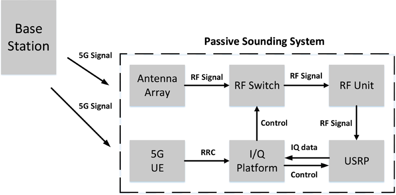
Figure 1: The diagram of passive sounding system.
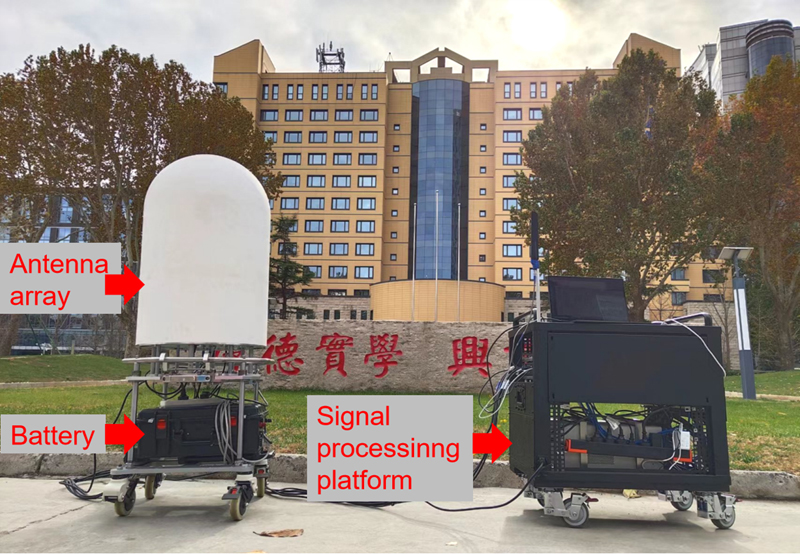
Figure 2: The photo of passive sounder.
The antenna array receives the electromagnetic signal transmitted from 5G base station and transforms it to the RF signal. Due to the high complexity and cost brought from massive RF channels, we adopt the RF switch to receive the signal alternatively with the time-division multiplexing (TDM) strategy. The switch interval should be no shorter than the 5G signal downlink period, e.g., ms for synchronization signal block (SSB) period, so that each antenna can receive an intact downlink signal. The RF unit, composed of filter and low noise amplifier (LNA), is able to eliminate the interference of out-of-band signals and strengthen the quality of in-band signals. An USRP device is used to convert the RF analogy signal to the I/Q digital signal with frequency conversion and sampling operations. The I/Q platform, namely a high performance workstation, is used to store and process the baseband I/Q signal transmitted from USRP. As to acquire the configuration of 5G cellular network, a 5G UE is used to obtain the radio resource control (RRC) parameters of the serving cell.
Figure 2 illustrates the practical photo of our developed passive sounder. The left-hand side contains antenna array and integrated RF switch, and the right-hand side contains the RF unit, USRP, I/Q platform and 5G UE. In order to receive the multipath impinging from various directions, a cylindrical antenna array with dual-polarized antenna elements is equipped. The radiation pattern of element and beam pattern of array for GHz are illustrated in Fig. 3. It is notable that the radiation pattern of antenna array has been calibrated with the over-the-air (OTA) method, e.g., multi-probe anechoic chamber and reverberation chamber [10] [11].
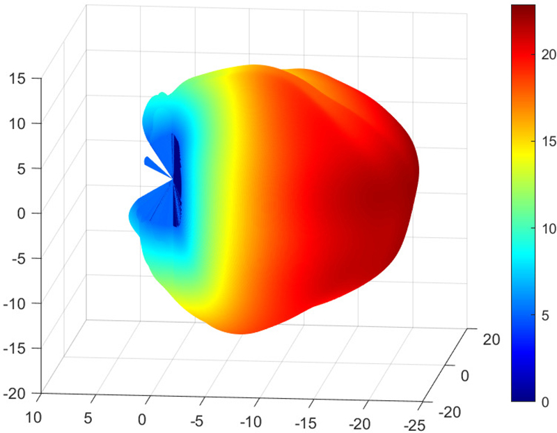
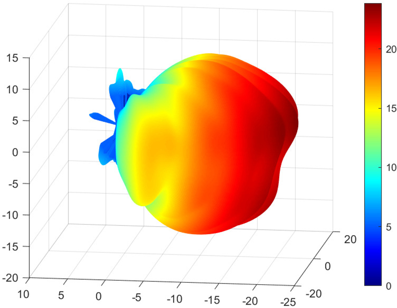
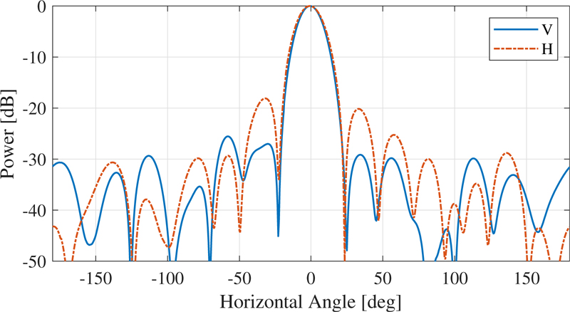
Figure 3: The radiation pattern of element and beam pattern of array: (a) element pattern of V, (b) element pattern of H, and (c) beam pattern in horizontal range..
III. DATA PROCESSING
A. 5G downlink signal extraction
The key of the passive sounding method is to utilize the 5G downlink signal, which is transmitted from the BS, to analyse the channel environment of 5G commercial cellular network. Thus, how to extract the 5G downlink signal efficiently and accurately is the prerequisite to perform the channel measurement. According to the 3rd generation partnership project (3GPP) physical layer specifications [12], the 5G BS is supposed to transmit several specific signals periodically over the cells, e.g., SSB and channel state information reference signal (CSI-RS).
The SSB signal, composed of the primary synchronization signal (PSS), secondary synchronization signal (SSS) and physical broadcast channel (PBCH), is the significant broadcast signal of 5G network. 5G UE is able to utilize the SSB signal to perform the time-frequency resource synchronization, cell search and master information block (MIB) acquisition. Each SSB consists of four consecutive orthogonal frequency division multiplexing (OFDM) symbols in time domain and twenty consecutive resource blocks (RBs) in frequency domain. The more details of SSB generation and transmission can be found in 3GPP technical specifications [12].
The extraction of SSB can be summarized as a three-step procedure. Firstly, determine the primary cell identify (PCI) and secondary cell identify (SCI) of serving cell by searching the peak of correlation between the received signals and the candidate signals generated by [12], e.g., PSS and SSS. Secondly, determine the SSB pattern and SSB index of the received SSB signal to obtain the location and sequence of demodulated reference signal (DMRS) for PBCH with the correlation-peak searching algorithm. Finally, with the known DMRS of PBCH, we can easily solve the MIB of serving cell by performing the channel estimation and decoding. Figure 4 illustrates the magnitude and phase of channel frequency response (CFR) of the extracted SSB burst, composed of eight TDM distributed SSBs, for 5G current network, respectively. It is indicated that the magnitude and phase of CFR vary over different SSBs, since each SSB is transmitted with different beam weights to cover different serving areas.
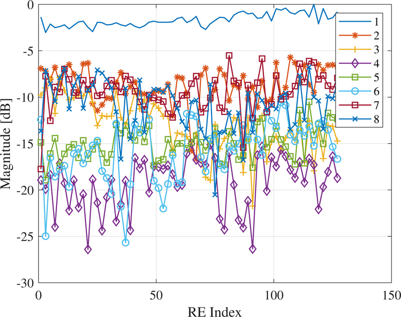
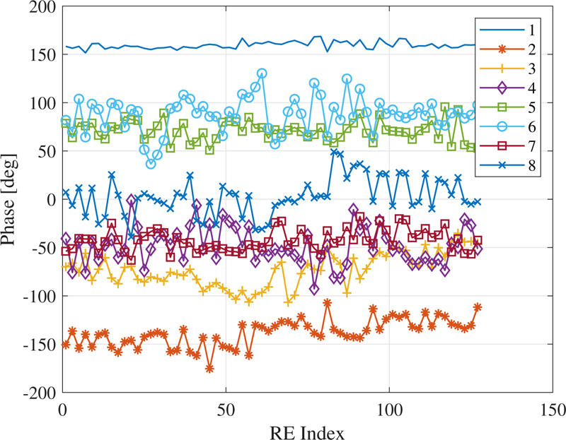
Figure 4: The (a) magnitude and (b) phase of CFR for different SSBs.
As to acquire the channel state information between BS and UE, 5G serving cell is supposed to transmit channel state information reference signal (CSI-RS) to the connected UE in a periodic or non-periodic manner. The application of CSI-RS can be categorized as these aspects: downlink channel state information acquisition, beam management, fine time-frequency tracking, and mobility management. Different from the SSB, the CSI-RS can be configured as multiple resources and ports in different multiplexing strategies, e.g., code division multiplexing (CDM). The configuration of CSI-RS for the serving cell, such as time-frequency locations and scrambling identity, is determined by the RRC parameters. However, acquiring the real-time RRC parameters of 5G network is technically complicated. Thus, we adopt the 5G commercial UE to establish a RRC connection with the serving cell, and then export the desired RRC parameters into our device. By combining the obtained RRC parameters and MIB, we can readily acquire the CFR of CSI-RS. Figure 5 illustrates the power delay profiler (PDP) comparison between CSI-RS and SSB of the same serving cell with the obtained CFR. It is indicated that the PDP of CSI-RS contains more spikes and burrs compared with that of SSB, since the bandwidth of CSI-RS, i.e., MHz, is much larger than that of SSB, i.e., MHz. That is to say, CSI-RS is more suitable for channel measurement, due to its higher resolution of delay domain.
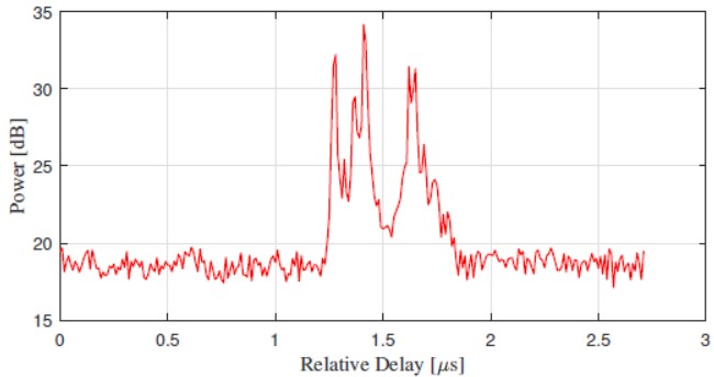
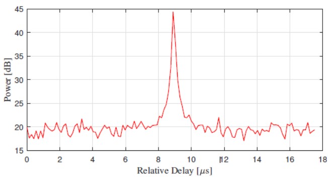
Figure 5: The PDP comparison between (a) CSI-RS and (b) SSB.
B. Multipath parameter estimation
After obtaining the channel transfer function between the BS and the sounder, it is crucial to analyse the propagation characteristics of channel environment. Many multi-dimensional parameter estimation algorithms have been proposed to solve the multipath component (MPC) parameters, e.g., maximum likelihood (ML) algorithm. The space-alternating generalized expectation-maximization (SAGE) algorithm [4], considered as a good choice for the low calculation complexity and high estimation accuracy, is utilized to extract the parameters of MPC in this paper.
Considering a stationary scenario, where the Doppler frequency is assumed to be , the complete observable signal of th frequency bin can be formulated as:
| (1) |
By introducing of the expectation-maximization (EM) concept [13], the SAGE algorithm is able to solve the MPC parameters with a low calculation complexity iteratively. The estimation of MPC parameter derived by SAGE algorithm can be expressed as:
| (3) | ||
| (4) |
Figure 6 illustrates the estimation result with the SAGE algorithm, where the background denotes the estimated power angular spectrum (PAS). The blue dots and arrows denote the estimated paths and its polarization directions. It is noted that the size of blue dot denotes the power of estimated path. Four specular paths have been resolved with the SAGE algorithm, and each of them locates at the peak of estimated PAS. It is indicated that the SAGE algorithm is able to extract the incident paths from different arrival directions efficiently.
IV. RESULTS AND ANALYSIS
A. Measurement environment
The channel measurement campaign is carried out in the office campus of China academy of information and communications technology, located in Beijing, China. Figure 7 illustrates the satellite photo of the measurement environment. As shown in Fig. 7, this office campus is a complicated UMa scenario, surrounded by buildings and parking lots. It is noted that the red lines and letters represent the measurement path. For instance, route is the road in front of the building .
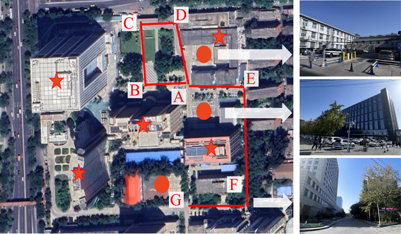
Figure 7: The satellite photo of measurement environment, where the star denotes the building and the solid dot denotes the parking lot.
The total measurement route is m length, covering the main roads of this office campus. In this measurement, total points are measured with m spacing and channel segments are collected at each point. Finally, a total of channel segments are obtained. Moreover, Table 1 lists the parameters of the measurement campaign. It is noted that the CSI-RS is chosen to analyse the MPC parameters for propagation environment due to its high resolution of delay domain.
Table 1: Measurement parameters
| Measurement Length | m |
| Measurement Step | m |
| Channel Segments | |
| Frequency Band | (MHz) |
| Subcarrier Spacing | kHz |
| Bandwidth | MHz |
| Signal to Analysis | CSI-RS |
| CSI-RS Periodicity | ms |
B. Multipath parameters
As to illustrate the multipath extraction process more deeply, two channel sounding results of typical LOS and NLOS scenarios are provided in Fig. 8 and Fig. 9, respectively. As depicted in Fig. 8 (a), the estimated PAS of LOS scenario contains two specular peaks, which contributes to the LOS path and ground reflection path respectively, since these two PAS peaks have similar horizontal angles but symmetrical elevation angles. We can observe that the estimated paths locate in the areas of estimated PAS with high power, implying that the multipath extraction algorithm is quite effective over the spatial domain. Moreover, it is noted that the polarization direction of estimated path is omitted for the sake of simplicity.
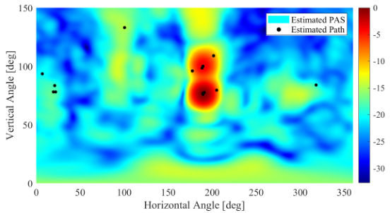
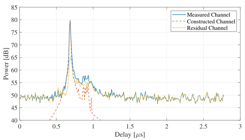
Figure 8: The extracted multipath result of LOS scenario: (a) estimated PAS and paths, and (b) channel construction of PDP.
Figure 8 (b) indicates the channel construction results in PDP domain, where the constructed channel denotes the CIR generated with the estimated paths and the residual channel denotes the subtraction of measured and constructed channel. We can observe that the PDP shapes of measured and constructed channel are quite similar, indicating that the measured channel is reconstructed well with the estimated multipath. Moreover, the residual channel still exists in Fig. 8 (b), whose PDP peak is dB lower that that of measured channel, probably caused by the dense multipath component(DMC) [14].
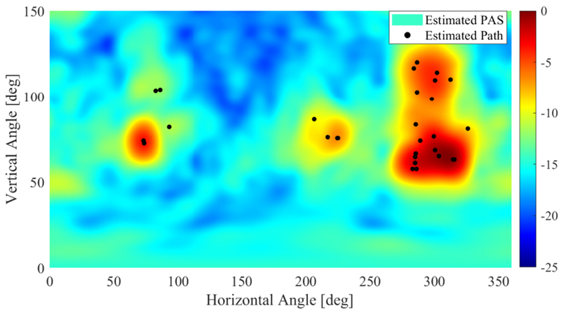
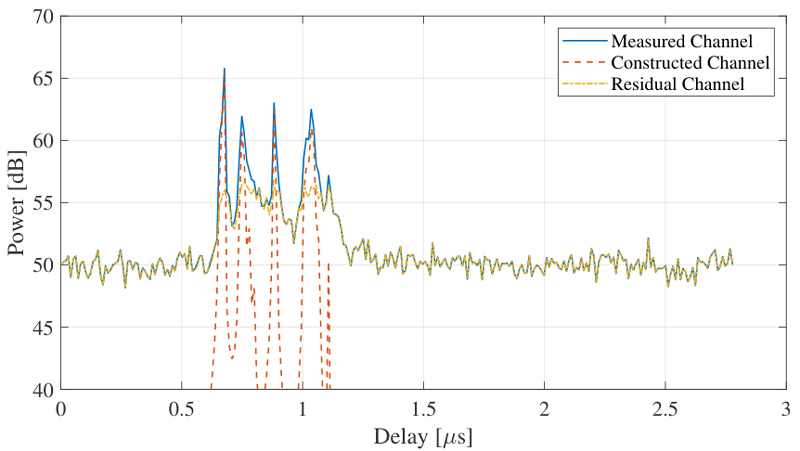
Figure 9: The extracted multipath result of NLOS scenario: (a) estimated PAS and paths and (b) channel construction of PDP.
Figure 9 provides the extracted multipath result of NLOS scenario. It can be indicated that the channel of NLOS scenario has a more dispersive distribution over spatial and delay domain, since the estimated PAS and PDP spectrums have more peaks than that of LOS scenario. Moreover, the measured channel can still be reconstructed well with the estimated multipath, indicating that we can extract the multipath efficiently both in LOS and NLOS scenarios.
C. Path loss and shadow fading
The path loss (PL) and shadow fading (SF) are of great significance to estimate the link budget and coverage of 5G cellular network. In the passive sounding framework, it is typically assumed that the transmission power of BS is constant. Thus, the receiving power, which is the superposition of transmission power and propagation loss, can be used to reflect the PL and SF of wireless channel. In this paper, as to eliminate the interference of neighbour cell, we adopted the power of constructed power for CSI-RS, illustrated in Fig. 8 (b) and Fig. 9 (b), as the receiving power of serving cell. According to the close-in (CI) free space reference distance model, the PL and SF can be written as:
| (7) |
Figure 10 illustrates the comparison between our measured model, 3GPP model and free space model. , denoting the power difference between the measured site with distance and the reference site with distance , is adopted to model the PL and SF of propagation environment, due to the lack of absolute transmission power of BS [9]. In this campaign, we chose measurement data located in the route to analysis the PL and SF, composed of a total measurement segments. From the fitted model, we can solve the PLE and the standard deviation . Compared with the 3GPP model, i.e., , and free space model, i.e., , the obtained PLE is a little larger, since we adopt the planar distance between the BS and measurement location. Moreover, the standard deviation is smaller than that of 3GPP model due to the few obstacles existed in the measurement environment.
D. RMS spreads
The root mean square (RMS) spread of extracted MPC parameters is further discussed with the obtained SAGE results to analyse the statistical characteristics of channel environment for measured scenario. The RMS spread of MPC parameter can be calculated as:
| (8) | ||
| (9) |
As depicted in Fig. 11, the calculated RMS spread of MPC parameters in logarithmic form for LOS and NLOS scenarios can be well fitted with the normal distribution. It can be observed that the RMS spread of NLOS scenario is larger than that of LOS scenario, due to more scatters and reflectors of propagation environment. That also can be illustrated in Fig. 8 and Fig. 9 that the MPC parameters of NLOS scenario have a more dispersive distribution over spatial and delay domains.
Table 2 lists the comparison between the calculated mean value and standard deviation and those presented in 3GPP 38.901 [16]. It shows that our results are commonly smaller than those of 3GPP, probably due to the effect of beamforming from 5G BS. According to 3GPP specifications, 5G BS is supposed to focus the transmit power on one or several directions, i.e., beamforming, to compensate the propagation path loss. That is to say, the recorded channel is actually the integration of beamforming effect from 5G BS and physical propagation environment, resulting in smaller spreads of spatial and delay domains.
Table 2: The comparison of RMS spread between measurement and 3GPP[16] results
| RMS Spread | Measured | 3GPP | |||
| LOS | NLOS | LOS | NLOS | ||
| ASA | 1.366 | 1.621 | 1.81 | 1.96 | |
| 0.450 | 0.285 | 0.20 | 0.11 | ||
| ESA | 1.028 | 1.173 | 0.95 | 1.38 | |
| 0.179 | 0.275 | 0.16 | 0.16 | ||
| Delay | -7.90 | -7.36 | -7.03 | -6.44 | |
| 0.502 | 0.502 | 0.66 | 0.39 |
V. CONCLUSION
In this paper, a channel sounding system available for 5G cellular network based on passive sounding method is proposed to analyse the channel characteristics of realistic commercial network. This system, which regards the 5G BS as the transmitter, is able to receive and decode the 5G downlink signal with the TDM scheme. Based on the decoded 5G downlink signal, e.g., SSB and CSI-RS, the proposed system can extract the MPC parameters between the 5G BS and the sounder with the SAGE algorithm. Moreover, a measurement campaign is carried out at a typical office campus. The measured results indicate that the proposed system is able to capture the channel characteristic of 5Gnetwork.
REFERENCES
[1] M. Agiwal, A. Roy, and N. Saxena, “Next generation 5G wireless networks: A comprehensive survey,” IEEE Communications Surveys and Tutorials, vol. 18, no. 3, pp. 1617-1655, Thirdquarter 2016.
[2] C.-X. Wang, J. Bian, J. Sun, W. Zhang, and M. Zhang, “A survey of 5G channel measurements and models,” IEEE Communications Surveys and Tutorials, vol. 20, no. 4, pp. 3142-3168, Fourthquarter 2018.
[3] C. U. Bas, R. Wang, S. Sangodoyin, S. Hur, K. Whang, J. Park, J. Zhang, and A. F. Molisch, “28 GHz propagation channel measurements for 5G microcellular environments,” The Applied Computational Electromagnetics Society Journal (ACES), vol. 34, no. 02, pp. 363-364, July 2021.
[4] B. Fleury, M. Tschudin, R. Heddergott, D. Dahlhaus, and K. Ingeman Pedersen, “Channel parameter estimation in mobile radio environments using the SAGE algorithm,” IEEE Journal on Selected Areas in Communications, vol. 17, no. 3, pp. 434-450, Mar. 1999.
[5] J. Huang, Y. Liu, C.-X. Wang, J. Sun, and H. Xiao, “5G millimeter wave channel sounders, measurements, and models: Recent developments and future challenges,” IEEE Communications Magazine, vol. 57, no. 1, pp. 138-145, Jan. 2019.
[6] X. Cai, X. Yin, X. Cheng, and A. Pérez Yuste, ‘‘An empirical random-cluster model for subway channels based on passive measurements in UMTS,” IEEE Transactions on Communications, vol. 64, no. 8, pp. 3563-3575, Aug. 2016.
[7] T. Zhou, C. Tao, S. Salous, L. Liu, and Z. Tan, “Implementation of an LTE-based channel measurement method for high-speed railway scenarios,” IEEE Transactions on Instrumentation and Measurement, vol. 65, no. 1, pp. 25-36, Jan.2016.
[8] X. Cai, J. Rodríguez-Piñeiro, X. Yin, N. Wang, B. Ai, G. F. Pedersen, and A. P. Yuste, “An empirical air-to-ground channel model based on passive measurements in LTE,” IEEE Transactions on Vehicular Technology, vol. 68, no. 2, pp. 1140-1154, Feb. 2019.
[9] T. Wu, X. Yin, L. Zhang, and J. Ning, “Measurement-based channel characterization for 5G downlink based on passive sounding in sub-6 GHz 5G commercial networks,” IEEE Transactions on Wireless Communications, vol. 20, no. 5, pp. 3225-3239, 2021.
[10] H. Pei, X. Chen, X. Huang, X. Liu, X. Zhang, and Y. Huang, “Key issues and algorithms of multiple-input-multiple-output over-the-air testing in the multi-probe anechoic chamber setup,” Science China Information Sciences, vol. 65, no. 131302, Feb. 2022.
[11] J. Yi, C. Dong, W. Xue, and X. Chen, “A switchable metamaterial absorber for fine- tuning of the coherence bandwidth in a reverberation chamber,” IEEE Transactions on Antennas and Propagation, vol. 70, no. 6, pp. 4908-4913, 2022.
[12] NR; Physical Channels and Modulation, vol. 16.3.0, 3rd Generation Partnership Project (3GPP), Technical Speciation (TS) 38.211, Sep.2020.
[13] M. Feder and E. Weinstein, “Parameter estimation of superimposed signals using the EM algorithm,” IEEE Transactions on Acoustics, Speech, and Signal Processing, vol. 36, no. 4, pp. 477-489, Apr. 1988.
[14] S. Jiang, W. Wang, Y. Miao, W. Fan, and A. F. Molisch, “A survey of dense multipath and Its impact on wireless systems,” IEEE Open Journal of Antennas and Propagation, vol. 3, pp. 435-460, 2022.
[15] J. Zhang, D. Dong, Y. Liang, X. Nie, X. Gao, Y. Zhang, C. Huang, and G. Liu, ‘‘Propagation characteristics of wideband MIMO channel in urban micro-and macrocells,” pp. 1-6, 2008.
[16] Study on channel model for frequencies from 0.5 to 100 GHz, vol. 14.2.0, 3rd Generation Partnership Project (3GPP), Technical Report (TR) 38.901, Sep. 2017.
BIOGRAPHIES

Hao Sun received the master’s degree from the Beijing University of Posts and Telecommunications, Beijing, China, in 2021. He is currently an engineer with the China Academy of Information and Communications Technology, Beijing. His current research interests include over-the-air testing, channel measurement and channel modeling.

Lei Li received the master’s degree from the Beijing University of Posts and Telecommunications, Beijing, China, in 2016. He is currently a senior engineer with the China Academy of Information and Communications Technology, Beijing. His current research interests include over-the-air testing for 5G devices and C-V2X, channel measurement and channelmodeling.

Wenqiang Tian received his Ph.D. degree from University of Chinese Academy of Sciences in 2015. Now, he is a senior Standardization Engineer of Guangdong OPPO Mobile Telecommunications Corp., Ltd. He has participated in the 5G standardization work and focused on physical layer design in 3GPP R15 and R16. Since 2018, he has started the research of B5G/6G and led the study on AI empowered PHY.
ACES JOURNAL, Vol. 39, No. 10, 927–935
doi: 10.13052/2024.ACES.J.391011
© 2024 River Publishers