Calculative Method on Electromechanical Strength for Rectangular and T-Shaped Rail over a Flat Surface Armature
M. N. Saravana Kumar, R. Murugan, J. Lydia, and S. Leones Sherwin Vimalraj
1Department of Electronics and Communication Engineering
Kings Engineering College, Chennai, Tamil Nadu, India
dr.mnskphd@gmail.com
2Department of Electrical and Electronics Engineering
Bharath Institute of Higher Education and Research, Chennai, Tamil Nadu, India
ramumurugan_r@rediffmail.com
3Department of Electrical and Electronics Engineering
Easwari Engineering College, Chennai, Tamil Nadu, India
lydia.jeec@gmail.com
4Department of Electronics and Communication Engineering
Panimalar Engineering College, Chennai, Tamil Nadu, India
sherwin_leo@yahoo.com
Submitted On: September 12, 2023; Accepted On: October 25, 2024
ABSTRACT
The electromagnetic railgun launching (EMRL) system is a type of long-range projectile launch that does not require any chemical propellant and can accelerate masses ranging from milligrams to kilograms to velocities of more than several kilometers per second. To make the rail stronger, electromechanical strength analysis was performed by calculating the area’s moment of inertia and critical velocity. One of the most essential mechanical aspects of rails is their moment of inertia, which has a direct impact on critical velocity and launch performance. Geometry and material both have an impact on the rails’ electromechanical performance. This paper describes the increase in electromechanical performance achieved by constructing two types of rail cross-sections - rectangular rails and T-shaped rails - based on structural analysis and current distribution from coupled electromagnetic (EM) simulation. The investigation found that T-shaped rails have higher moments of inertia than rectangular rails for the same cross-sectional area and width. However, the mechanical performance differences between the two geometries are not significant. Therefore, the advantage of larger moments of inertia for a given cross-sectional area is limited. EM analysis has been extended to a 3-D finite element method (FEM) for both rails by linking it with Simplorer using the Maxwell-Simplorer coupled (MSC) method with a flat surface C-shaped armature. When compared to rectangular and T-shaped rails, the T-shaped rail has a lower current density at the inner curvature but a greater at the contact interface.
Index Terms: Area’s moment of inertia, armature velocity, critical velocity, dynamic analysis, electromagnetic railgun launching, electromechanical strength, Maxwell-Simplorer coupled.
I. INTRODUCTION
That a significant dynamic response with a moving armature might happen during railgun launch is a challenging event, because the rails are exposed to a hostile load environment. The rail-armature interface experiences significant contact pressure variations, which can cause damage under certain situations. High current density in railguns can cause high temperatures, resulting in strength loss, melting and erosion. Thus, launch performance depends on the mechanical characteristics as well as the current distribution of the rails.
Geometry and material are key factors influencing electromechanical performance. Zhou et al. [1] have scrutinized railgun key parameters such as height, width and separation between the rails for different cross-sections of rails. They investigated the changes in thickness, width, spacing and other rail geometric parameters which affect inductance gradient (L’), current density (J) and magnetic flux density (B). They implemented finite element analysis for examining the key parameters for different rail cross-sections. They assumed the rail is brass, 1 MA current and 60 Hz frequency. They simulated the geometries under Eddy current A.C. analysis and determined the result for geometries cross-sections of rail. Keshtkar [2] examined the effect of key parameters on varying the dimensional parameters of the railgun. Models of two-dimensional (2-D) finite element simulations were performed for the various w (width), h (height) and s (separation) values. L’ values for different geometrical parameters were calculated, and a table presented. Keshtkar concluded that to increase L’ the thickness and width of rails must be decreased whereas separation between rails ought to increase. Jin et al. [3] designed a cross-sectional geometry for calculating the area’s moment of inertia, one of the important properties of the rails that affects the critical velocity as well as the launch. They concluded that a convex rail cross-section shows larger inertia moment and current density distribution is smaller at the bore-side rail surface but greater at the contact surface, especially at the trailing edge of the armature.
The three-dimensional structure illustrated in Fig. 1 represents the dimensional parameters by considered rail to be at finite length with an armature placed between the rails to complete the current path. When the current flowing in Rail_1 passes through the armature it is returned back through Rail_2 and completes the circuit. As a result, a magnetic field is established in the space between the rails. This field interacts with the current to produce Lorentz forces.
Figure 1: Schematic three-dimensional geometric model of a railgun.
This paper investigates the moment of inertia for cross-sections of rectangular and T-shaped rails. Finite element method (FEM) simulations of rail dynamics are conducted for different rail types under identical conditions. The Maxwell-Simplorer coupled (MSC) technique is used for electromagnetic (EM) simulations to estimate current distributions.
II. STRUCTURAL ANALYSIS OF EM RAILS
During the railgun launch action, the rail receives a huge peak value and a brief duration of current pulses. The skin effect causes the pulse current to scatter in a very thin layer near the surface of each conductor. This complicates the EM study of the railgun. This study uses the finite element method to calculate the railgun inductance gradient.
Because real equipment is rather sophisticated, the simulation model in this research is simplified using the following assumptions. The two rails are spatially symmetrical, with identical constructions and materials. In comparison to the rail’s height and width, the rail’s length is adequate to construct a 2-D equivalent model. A 2-D model can be further simplified by considering the field distribution’s perfect symmetry [4].
The differential form of Maxwell’s equation is:
| (1) | ||
| (2) | ||
| (3) |
Therefore:
| (4) |
and Eddy current density:
| (5) |
The rail is supplied with a short period of high magnitude 300 kA pulsed current, resulting in a non-uniform current distribution and a hotspot at the rails’ inner corners. The rail will undergo many alterations during armature motion as a result of contact pressure and contact damage. This causes a rise in temperature, loss of mechanical strength, melting and erosion [3, 5]. The mechanical strength of the rail cross-section is explored by finding the area moment of inertia and critical velocity which determines the most efficient rail cross-section that might be used for EM launch.
Area cross-section is considered to be 1500 mm, and Fig. 2 depicts the dimensional parameters. For a rectangular rail the cross-sections are H40 mm, W37.5 mm. For a T-shaped rail the cross-sections are H40 mm, W38.5 mm, m4 mm and d30 mm [6, 7]. A comparison was done between the essential characteristics of the rectangular and the T-shaped rail cross-sections, which minimized the current hotspot appropriate for launch.
Figure 2: Cross-sectional geometry of rectangular and T-shaped rails.
The cross-sectional area for the rectangular rail:
| (6) |
The cross-sectional area for the T-shaped rail:
| (7) |
Table 1: Comparison of L’, J, B and F over the rectangular and T-shaped rail cross-sections
| Rail Cross-Section | L’ (H/m) | J10 (A/m) | B [T] | F (kN) |
| Rectangular | 0.46305 | 0.54381 | 4.6284 | 132.801 |
| T-shaped | 0.48481 | 0.34753 | 5.8247 | 129.387 |
Table 1 shows the design essential parameters such as inductance gradient (L’), current density (J), magnetic flux density (B) and Lorentz force (F) for the two rails. According to researchers [8, 9], both the rectangular and T-shaped rail cross-sections have an acceptable inductance gradient value. As a result, the current density concentration is limited across both rails.
The area’s moment of inertia for rectangular and T-shaped rail cross-section under consideration can be calculated by the following equations:
Moment of inertia for rectangular rail cross-section along the X’-X and Y’-Y axis as shown in Fig. 3.
Figure 3: Cross-section of rectangular rail.
| (8) | ||
| (9) |
Centroid for rectangular rail cross-section:
| (10) | ||
| (11) |
Moment of inertia for T-shaped rail cross-section along the X’-X and Y’-Y axis as shown in Fig. 4.
Figure 4: Cross-section of T-shaped rail.
| (12) | |||
| (13) |
Centroid for rectangular convex rail cross-section:
| (14) | ||
| (15) |
where:
Railgun launches can cause the rail to respond dynamically due to magnetic pressure. When the armature reaches its critical velocity, resonance might develop, causing high-amplitude tension and strain during passage and potentially damaging the rails [10]. Timoshenko [12] investigated the vibration of Bernoulli-Euler beams on an elastic base. Lewis and Nechitailo [11] proposed an expression for critical velocity, based on [12].
Rails’ critical velocity:
| (16) |
where E is the modulus of elasticity, I is the moment of inertia of the beam cross-section, is the density of the rail material and A is the rail cross-sectional area.
The normalized rail critical velocity at the time of launch can be calculated by using equation (16). Though the mechanical strength of the rail purely depends on the material property. So, the material chosen for the rail was [1–4] having modulus of elasticity (E) as 117 GPa, moment of inertia (I) of the beam cross-section, density () of the rail material as 8933 kg/m, rail cross-sectional area (A) as 1500 mm and foundation stiffness (K) as 610 N/m. The resultant values of inertia moment for all rail cross-sectional geometries are tabulated. For a comparative approach, the simulated values and calculated values of moment of inertia are shown in Table 2.
Table 2: Comparison of moment of inertia
| Rail Cross-Section | Centroidal Axis (mm) | Moment of Inertia, I ( 10 mm) | V (m/s) | |
| Simulated (Using ANSYS Tool) | Calculated (Using Empirical Equations) | |||
| Rectangular | (18.75, 20) | 1.7578 | 1.7429 | 128.78 |
| T-shaped | (18.79, 20) | 1.7795 | 1.7524 | 129.18 |
Table 2 indicates that the found equations for determining the area’s moment of inertia produce the same results as those acquired through simulation. The T-shaped rail cross-section has a greater mechanical strength of 1.7 mm and a critical velocity of 129 m/s, indicating its ability to resist launch.
III. DYNAMIC ANALYSIS ON EM RAILGUN USING MSC METHOD
Railgun armature plays a crucial function in the EM launching process. Two types of armatures were chosen for experimental consideration: C-shaped armature and brush armature. At the end of the simulation, the C-shaped armature demonstrated higher efficiency than the brush armature. Higher current concentration in the armature causes a rise in local temperature, resulting in loss of mechanical strength and even melting [13]. The armature is built so that it may be correctly aligned with the rectangular and T-shaped railgun for a 1 meter rail.
Figure 5: Design chart of MSC method.
The three-dimensional geometry was initialized by properly selecting the properties of the materials copper for rail with conductivity 5.810 (S/m) with a relative permeability of 0.999991 and aluminum for armature with conductivity 3.510 (S/m) with a relative permeability of 1.0. The boundary conditions and excitation of rails about 300 kA are assigned to the railgun by meshing it properly. The parameter sweep is used to calculate current density and magnetic field strength as the armature position moves in increments until it exits the rails. The ANSYS Maxwell EM solver is coupled with Simplorer to accomplish the MSC method, and simulation flow is clearly represented in Fig. 5.
Figure 6 depicts a 3040 mm flat surface armature that has been proposed to improve railgun performance by meeting the required railgun essential criteria such as minimal current density concentration and maximum EM armature force.
Figure 6: A 3040 mm flat surface C-shaped armature.
Wing angle of the armature tail (11.7), thickness of the armature (d13 mm), length of the armature tail (d35 mm), thickness of the armature tail (d6 mm), height of the armature spearhead (d22 mm), length of the armature (d50 mm), width of the armature (d40 mm), height of the armature (d30 mm), thickness of the armature spearhead (d7 mm), curvature radius of the armature throat (r8 mm) and curvature radius joining leading edge to armature spearhead (r11 mm). During the pre-processing stage the meshing is properly configured with 28234 domain elements, 5940 boundary elements and 790 edge elements. Degrees of freedom (DOF) for flat surface C-shaped armature are 18629 with internal DOF’s as 4882.

Figure 7: Pulsed power supply system.
Figure 7 depicts the pulsed power supply (PPS) system with pulsed capacitor circuit, switching circuit and pulse shaping elements that is outfitted with the railgun to generate 300 kA capacitive discharge pulse current, as shown in Fig. 8, to improve railgun performanceanalysis.
Figure 8: Capacitor discharge current.
The railgun model being fed with 300 kA of pulsed current from 0 to 2 ms and then reduced from 2 ms to 5 ms is illustrated in Fig. 7. This calculates the current density concentration between the armature and the rail for an armature distance of 40 mm from the rail’s breech end.
Figure 9: MSC method of computational system.
Figure 9 depicts the electrical equivalent circuit model of a railgun, which is used to determine the velocity and distance traveled by the projectile using the ANSYS coupled Simplorer. The subsystem model is provided with capacitor bank-based PPS, and the resulting emerging force causes the armature to move. The armature’s location is sensed and given back to the subsystem model by computing its velocity anddisplacement.
The closed loop model contains a discharge capacitor C1, input resistance R1, pulse shaping inductance equivalent model of the railgun system, a translational mass “MASS_TRB1”, a translational motion setting “S_TRB1” and time-controlled switches S1 and S2. The railgun will act as a subsystem which is initialized by current excitation which passes through the rails and the bullet. The output of the rail model is the Lorentz force “FORCE1_N” that is generated on the armature. This generated force propels the mass with the delta change in position to the delta change in time which is sensed and recorded by the displacement sensor “SM_TRB1”. This process is carried out until the bullet exits the rails.
IV. ELECTROMAGNETIC POST PROCESSING RESULTS
In the post processing stage, EM field plots and output parameter graphical plots can be obtained. To compute the armature velocity, a project variable has been developed for a flat surface C-shaped armature with an armature volume of 3.303910 m and an armature density of 1816.045 kg/m for a 60 gram armature.
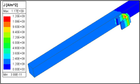
Figure 10: Current density field plot for rectangular railgun at armature distance of 40 mm.
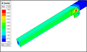
Figure 11: Magnetic flux density field plot for rectangular railgun at armature distance of 40 mm.
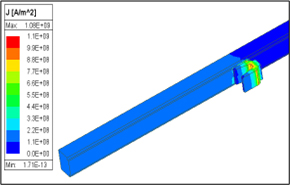
Figure 12: Current density field plot for T-shaped railgun at armature distance of 40 mm.
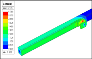
Figure 13: Magnetic flux density field plot for T-shaped railgun at armature distance of 40 mm.
On observing the field plots from Figs. 10–13, the current density concentration over the center curvature of the armature of the rectangular railgun is greater (1.179010 A/m) compared with the T-shaped railgun (1.070610 A/m). The current hotspot in the center curve of the armature causes melting due to temperature rise, resulting in damage to the armature before it leaves the muzzle.
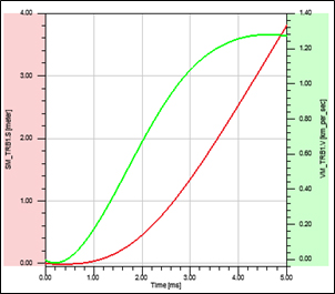
Figure 14: Armature velocity (VM_TRB1.v) of 1.25 km/s for rectangular railgun.
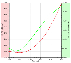
Figure 15: Armature velocity (VM_TRB1.v) of 0.9182 km/s for T-shaped railgun.
Figures 14 and 15 show the velocity and acceleration graphs for the rectangular and T-shaped railguns with 60 grams armature. For both types of railguns, the velocity obtained is nearly equivalent to 1 km/s for 60 grams of armature. When the parameters m and d of the T-shaped railgun are further dimensioned, the current density concentration will be reduced by raising the value of uniform current distribution to obtain maximum velocity.
V. CONCLUSION
In this paper, the area’s moment of inertia is investigated for rectangular and T-shaped rail cross-sections, and FEM simulations of railgun dynamics are done under identical circumstances. ANSYS MSC simulations are run for the two different rail geometries. The findings reveal the following:
The cross-sectional area was kept constant at 1500 mm by modifying the rail’s dimensional properties. T-shaped rails have a greater moment of inertia than flat rails for the same cross-sectional area and rail width. The high moment of inertia can delay the occurrence of maximum displacement, although this impact is subtle since the critical velocity is determined by the fourth root of the moment of inertia. As a result, the T-shaped rail cross-section has a higher mechanical strength (1.7 mm) and critical velocity (129 m/s), allowing it to withstand the launch.
Simulations of rail dynamics using a flat surface C-shaped armature show no significant changes in mechanical performance between the two rail designs. As a result, the benefits of bigger moments of inertia for a given cross-sectional area arelimited.
Compared to rectangular and T-shaped rails, T-shaped rails have lower current density at the inner curvature but higher at the contact interface.
REFERENCES
[1] Y. Zhou, P. Yan, W. Q. Yuan, J. Wang, and M. T. Li, “Current distribution and inductance gradient calculation at different rail geometric parameters,” in 2009 IEEE Pulsed Power Conference, Washington, DC, pp. 1290-1293, 2009.
[2] A. Keshtkar, “Effect of rail dimension on current distribution and inductance gradient,” in 2004 12th Symposium on Electromagnetic Launch Technology, Snowbird, UT, pp. 359-362, 2004.
[3] L. Jin, B. Lei, Q. Zhang, and R. Zhu, “Electromechanical performance of rails with different cross-sectional shapes in railgun,” IEEE Transactions on Plasma Science, vol. 43, no. 5, pp. 1220-1224, May 2015.
[4] S. Liu, J. Ruan, Z. Du, D. Wang, and C. Zhao, “Calculation of railgun inductance gradient by 2-D finite element method,” in 2008 International Conference on Electrical Machines and Systems, Wuhan, pp. 4057-4060, 2008.
[5] L. Jin, B. Lei, Z. Li, and Q. Zhang, “Comparison simulation of friction heat and joule heat in electromagnetic railgun,” Applied Mechanics and Materials, vol. 203, pp. 401-405, 2012.
[6] M. N. Saravana Kumar and R. Murugan, “Analysis of inductance gradient and current density distribution over different cross-section of rails,” International Journal of Electrical and Computer Engineering, vol. 8, no. 02, pp. 723-729,2018.
[7] M. N. Saravana Kumar, R. Murugan, and Shivkumar Poorani, “Inductance gradient and current density distribution for T-shaped convex and concave rail cross-sections,” International Journal of Engineering & Technology (UAE), vol. 7, no. 01, pp. 237-240, 2018.
[8] A. Keshtkar, Z. Jafari Khorrami, and L. Gharib, “Comparison of inductance gradient and electromagnetic force in two types of railguns with two projectiles by finite element method,” IEEE Transactions on Plasma Science, vol. 45, no. 8, pp. 2387-2392, 2017.
[9] M. S. Bayati, A. Keshtkar, and S. V. A.-D. Makki, “Analyzing the current distribution, magnetic field and inductance gradient at the circular rail in comparison to rectangular rail,” in 2012 16th International Symposium on Electromagnetic Launch Technology, Beijing, China, pp. 1-5, 2012.
[10] K. Daneshjoo, M. Rahimzadeh, R. Ahmadi, and M. Ghassemi, “Dynamic response and armature critical velocity studies in an electromagnetic railgun,” IEEE Trans. Magn., vol. 43, no. 1, pp. 126-131, Jan. 2007.
[11] K. B. Lewis and N. V. Nechitailo, “Transient resonance in hypervelocity launchers at critical velocities,” IEEE Trans. Magn., vol. 43, no. 1, pp. 157-162, Jan. 2007.
[12] S. Timoshenko, “Method of analysis of statistical and dynamical stresses in rail,” in Proc. 2nd Int. Congr. Appl. Mech., Zürich, Switzerland, pp. 1-12, 1927.
[13] J. Gallant and P. Lehmann, “Experiments with brush projectiles in a parallel augmented railgun,” IEEE Transactions on Magnetics, vol. 41, no. 1, pp. 188-193, 2005.
BIOGRAPHIES

M. N. Saravana Kumar received a bachelor’s degree in Electronics and Communication Engineering from Bhajarang Engineering College, Chennai, India, in 2009. He received his master’s degree in Power Electronics and Drives from Rajalakshimi Engineering College, Chennai, India, in 2013, and Ph.D. degree in Electrical and Electronics Engineering from St. Peter’s Institute of Higher Education and Research, Chennai, India, in 2019. His main areas of interest are power electronics and drives, electric machine designing, electromagnetic field computation and modelling.

R. Murugan received a bachelor’s degree in Electrical and Electronics Engineering from University of Madras, Tamil Nadu, India, in April 1996. He received his master’s degree in High Voltage Engineering from College of Engineering, Anna University, Guindy, Chennai, Tamil Nadu, India, in February 1999, and Ph.D. degree in Electrical and Electronics Engineering from Anna University, Chennai, Tamil Nadu, India, in 2011. His main areas of interest are electromagnetic field and high voltage engineering.

J. Lydia has completed her Ph.D. degree under the Faculty of Electrical Engineering, Anna University, Chennai, India. She received the B.E. degree in Electrical and Electronics Engineering from Easwari Engineering College, Chennai, India. She received the M.E. degree in Power Electronics and Drives from the Karunya Institute of Technology and Sciences, Deemed University, in 2006. She is currently an Assistant Professor with the Department of Electrical and Electronics Engineering, Easwari Engineering College, and works in the fields of electromagnetic fields and high-voltage engineering. She is a member of MISTE.

S. Leones Sherwin Vimalraj is a Professor in the Department of Electronics and Communication Engineering, Panimalar Engineering College, Chennai, India. He completed his B.E. in Electronics and Communication Engineering from Karunya Institute of Technology, Bharathiar University, India, in 2001. He obtained his M.E. in Optical Communication Engineering (2004) from College of Engineering, Guindy, Anna University, and Ph.D. in Wireless Communication Engineering (2015) from Dr. MGR Educational and Research Institute, Deemed University, Chennai, India. His research areas include wireless communication, network engineering, computing and evolutionary algorithms.
ACES JOURNAL, Vol. 39, No. 9, 823–830
doi: 10.13052/2024.ACES.J.390908
© 2024 River Publishers