Wideband Cup Dielectric Resonator Antenna With Stable Omnidirectional Patterns
Shuxin Zheng, Nan Yang, Xiaoming Chen, Zhen-Yuan Zhang, Bingyi Qian, and Ahmed A. Kishk
1School of Information and Communications Engineering
Xi’an Jiaotong University, Xi’an 710049, China
zheng21761@stu.xjtu.edu.cn, xiaoming.chen@mail.xjtu.edu.cn, Qianbingyi@stu.xjtu.edu.cn
2School of Electronics and Information Technology (School of Microelectronics) and Guangdong Provincial Key
Laboratory of Optoelectronic Information Processing Chips and Systems
Sun Yat-sen University, Guangzhou 510006, China
yangnan6@mail.sysu.edu.cn
3Department of Electrical and Electronic Engineering
South University of Science and Technology of China, Shenzhen 518055, China
Zhangzhen-yuan@outlook.com
4Department of Electrical and Computer Engineering
Concordia University, Montreal, QC H3G 1M8, Canada
kishk@encs.concordia.ca
Submitted On: September 13, 2023; Accepted On: August 30, 2024
ABSTRACT
A wideband omnidirectional cup dielectric resonator antenna (CDRA) is designed by utilizing three modes (DR TM, coil, and monopole modes) for the first time. It deploys the modified coil feeding structure comprising four coil segments and two close-by probes. The four coil segments provide an equivalent magnetic-current loop and the two probes act as an electric monopole. Thus, the modified feeding structure can excite the DR TM mode and two neighbor resonances extending the operating bandwidth. All of these modes have omnidirectional characteristics. To verify the idea, a CDRA is designed, fabricated, and measured. The CDRA is (where is the free-space wavelength at the center frequency) with a bandwidth of 67.7% (3.28-6.64 GHz). The antenna has stable omnidirectional radiation patterns, high radiation efficiencies, and a low cross-polarized level within the operating bandwidth.
Index Terms: Dielectric resonator antenna (DRA), omnidirectional, wideband.
I. INTRODUCTION
Dielectric resonator antennas (DRAs) have attracted tremendous attention for their compact sizes, various radiation patterns, bandwidths, and high efficiencies. Omnidirectional DRAs can be used for various wireless communications because of their broad coverage [1–4]. However, designing a wideband and compact DRA with a stable omnidirectional pattern is nontrivial.
Many omnidirectional antennas exist in the literature [1–30]. There are various traditional methods to realize omnidirectional antenna, such as a wire in free space [5], exciting the circular patch antenna’s higher-order modes [5], and loading the circular patch antenna with an annular ring [6–8]. Antennas, with four bent dipoles [9], based on substrate integrated waveguides (SIWs) [10], and with surface wave [11], all had omnidirectional radiation patterns. However, the antennas’ bandwidths are usually narrow (less than 10%). Exciting multiple modes can broaden antennas’ bandwidths [12, 13]. An electrically small and omnidirectional antenna with a bandwidth of 32% was presented [12]. Antenna arrays are usually used to extend bandwidth [14]. A circular dual-band monopole antenna array was designed in [14]. Omnidirectional DRAs have been designed in different shapes, including rectangles [15, 16], hemispheres [17], and cylinders [18–26]. A three-dimensional (3-D) printed omnidirectional multi-ring DRA was excited in three DR modes (TM, TM, and TM modes) with a bandwidth of 60.2% [24]. Combining a monopole antenna and a DRA is an effective way to realize an omnidirectional wideband antenna [27–30] at the expense of raising the profile. A hybrid antenna could offer an impedance bandwidth of up to 138% [30]. Most existing works try to extend the bandwidth at the cost of increasing the antenna’s dimensions [24] or sacrificing the stability of the radiation pattern [13, 30].
A coil feeding structure was first used in [19] to realize an omnidirectional cup dielectric resonator antenna (CDRA) with a 29.5% bandwidth. By improving the structure and the coil feeding mode, three modes are excited and the bandwidth reaches 67.7% with a stable omnidirectional pattern.
The modified coil feeding structure, with two ends excited equally and in phase, comprises four coil segments and two probes. The four coil segments have an equivalent magnetic-current loop and two probes act as a single monopole. Optimizing the coil and dielectric resonator (DR) parameters, the coil excites the TM mode of the CDRA and two omnidirectional modes (coil and monopole modes) at neighbor frequencies simultaneously. Thus, a wideband omnidirectional CDRA is achieved. Then, a prototype is fabricated and measured to demonstrate the scheme. The measured and simulated results are in reasonable agreement. The size of the CDRA is 0.61 0.32 ( is the free-space wavelength at the center frequency). The CDRA’s bandwidth is 67.7% from 3.28 GHz to 6.64 GHz. Within the operating band, the CDRA has high radiation efficiencies, stable radiation patterns, and low cross polarizations. As listed in Table 1, the proposed antenna has a broader bandwidth and a smaller size.
Table 1: Comparison between proposed omnidirectional CDRA and relevant works first
| Ref. | AntennaTypes | Dimensions(Diameter Height) | Band-width | Omnidirectional Pattern |
| [19] | DRA | 29% | Stable | |
| [24] | Multi-ring DRA | 60% | Stable | |
| [25] | DRA | 42% | Unstable | |
| [26] | DRA | 34% | Stable | |
| [30] | DRA + Monopole | 138% | Unstable | |
| ThisWork | DRA | 68% | Stable |
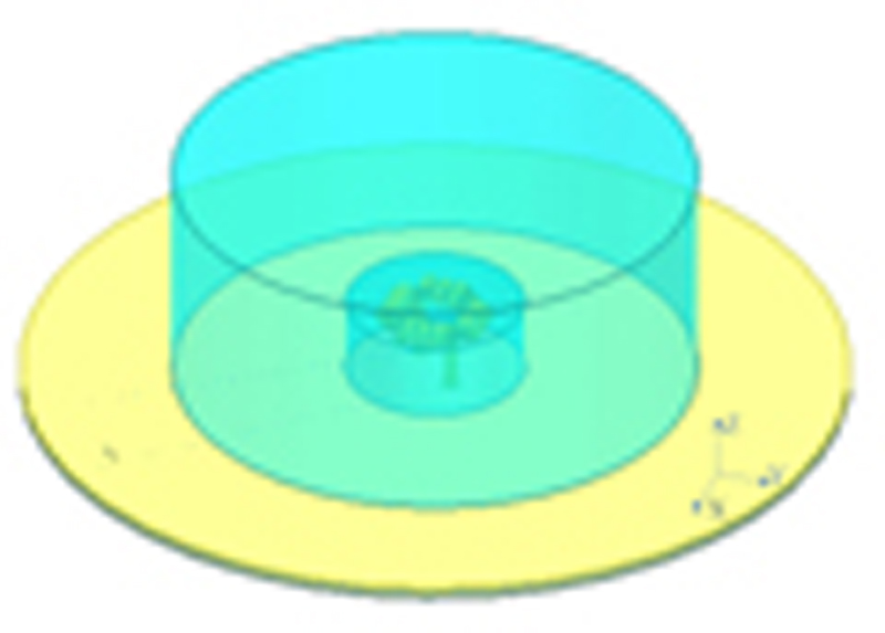
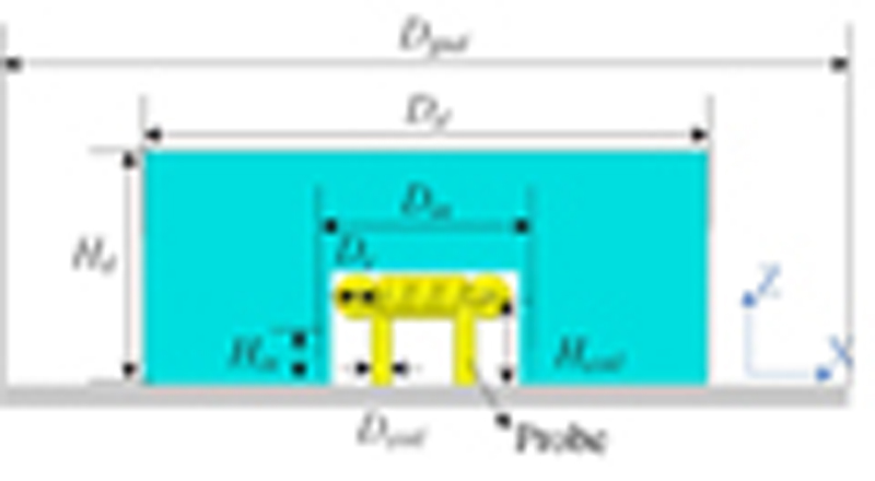
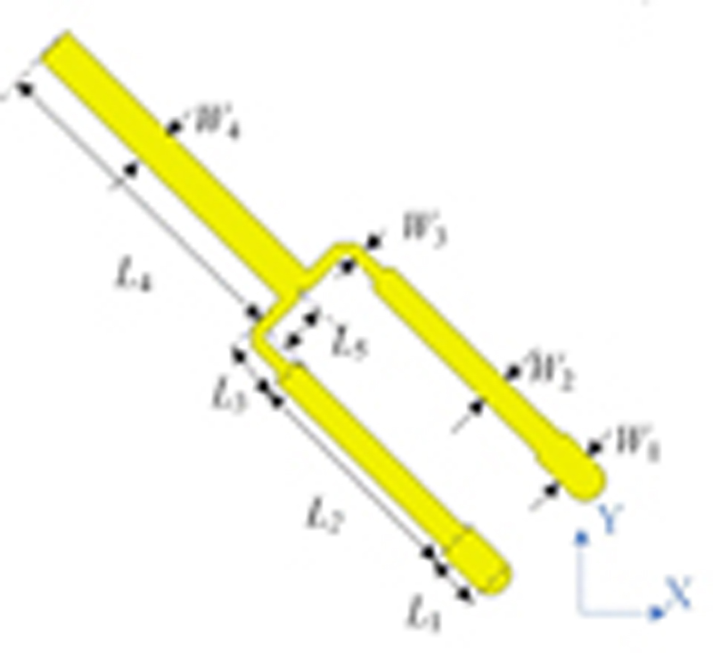
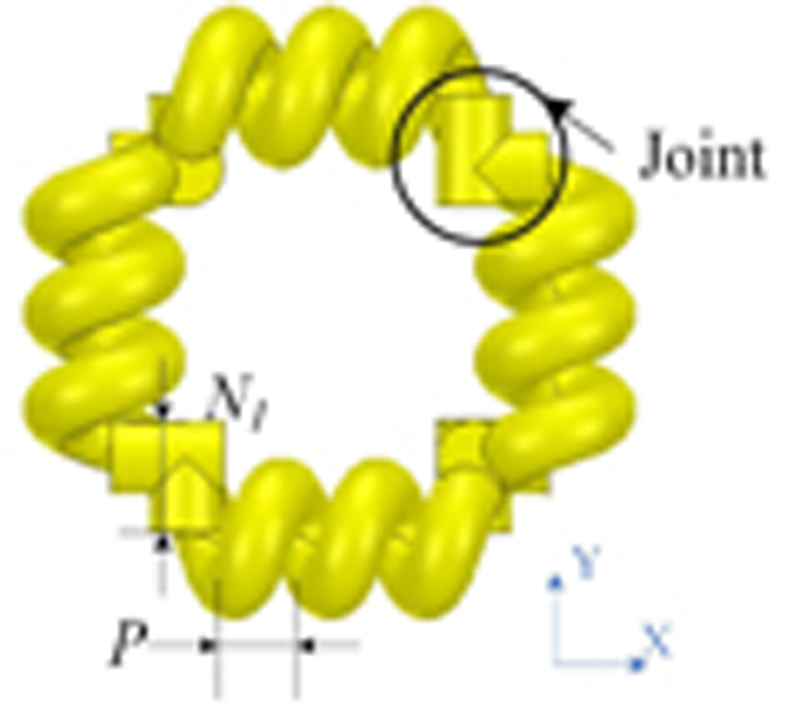
Figure 1: CDRA: (a) isometric view and (b) front view. Top view of (c) T-junction power divider and (d) feeding structure.
II. ANTENNA STRUCTURE
The CDRA’s configuration is shown in Fig. 1. The cup dielectric (D, H, D, H) manufactured of K9-glass (6.9) is located on a circular substrate with a diameter of D, as can be seen in Fig. 1 (b). FR-4 (4.3) is the substrate material with a loss tangent of 0.025 and a thickness of 0.8 mm. The coil feeding structure is made of a copper wire with a diameter of D. The coil’s pitch, height, turns, and inner diameter are represented by H, P, N, and D, respectively. As described in Fig. 1 (d), the joint length between the two coils is N. The T-junction power divider, as shown in Fig. 1 (c), is loaded on the dielectric surface side of the FR-4 substrate. All dimensions of the CDRA are listed in Table 2.
Table 2: Dimensions of the CDRA (unit: mm)
| D | D | H | D | H | H |
| 60 | 14.6 | 16.5 | 37 | 5.6 | 5 |
| D | P | D | L | L | L |
| 1 | 1.2 | 0.6 | 3 | 9.2 | 2 |
| L | L | W | W | W | W |
| 8 | 2.7 | 1.5 | 1.15 | 0.55 | 1.5 |
| N | N | ||||
| 3 | 1 |
III. OPERATING MECHANISM
The basic coil, creating an equivalent magnetic-current loop, excites two modes (DR TM mode and coil mode) to realize an omnidirectional CDRA with a bandwidth of 29% [19]. Based on that, a modified coil excites an additional resonance (probe mode) to double the bandwidth of the CDRA. The evolution process of the CDRA can be divided into three steps.
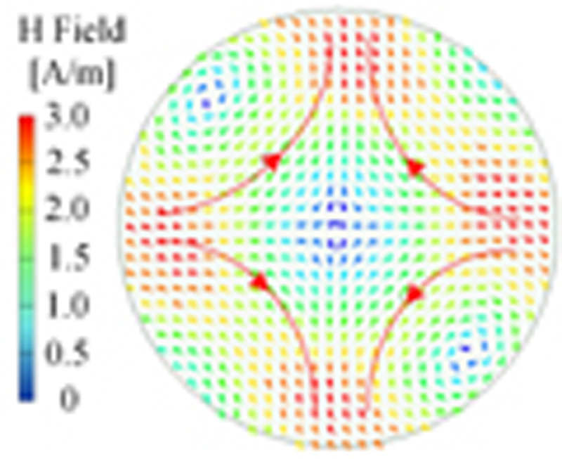
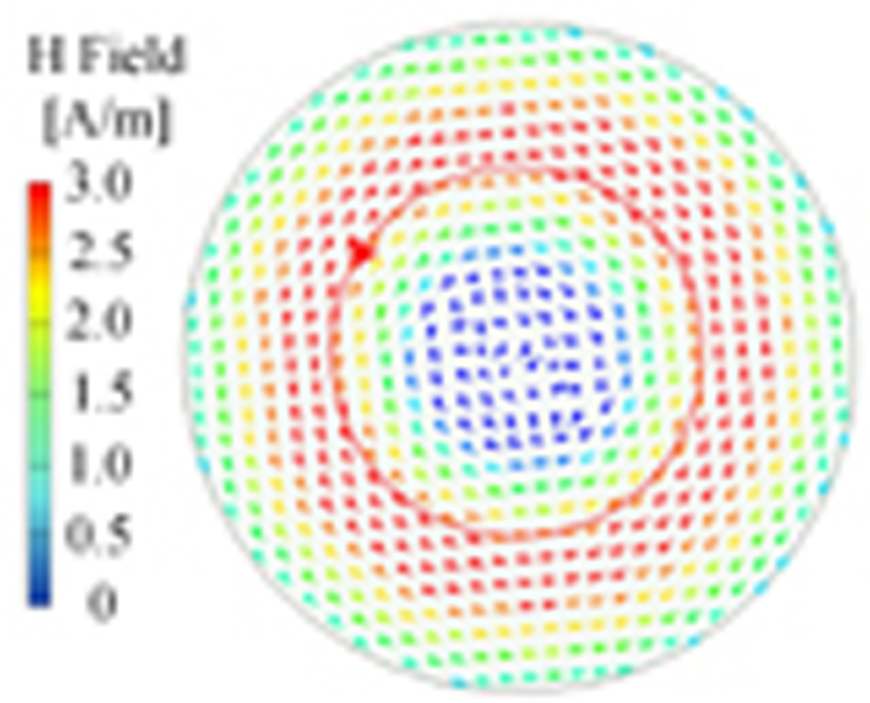
Figure 2: Magnetic field of (a) HEM mode (the distance between two probes is 14.3 mm) and (b) monopole mode (the distance between two probes is 7.6 mm).
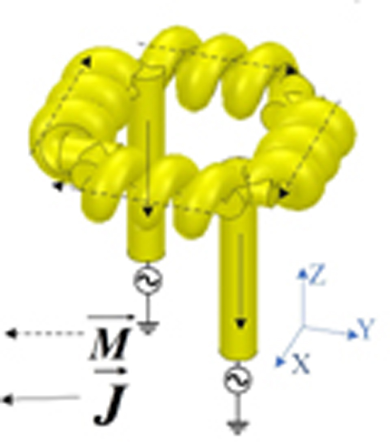
Figure 3: Equivalent magnetic-current loop and monopole of a coil feeding structure.
Step 1: Introduce probe mode. In [19], the probes only support the coil to control the height of the coil. The probe lengths are short for the coil image to be close to the original coil. Thus, the equivalent magnetic-current loop and its image are very close to each other and constructively contribute to the increase of the antenna gain. The probes are elongated to enhance their influence. The increased diameter of the copper and shortened helical coil pitch are used to maintain the strength of the magnetic field. The probes’ current directions change as the probes’ length increases. The probes are excited equally and in phase to have their electrics in the same direction. However, the two probes excite the HEM mode of the DR, which undermines the omnidirectional property.
Step 2: Avoid exciting the HEM mode. As depicted in Fig. 2, the excited mode (HEM mode or monopole mode) is determined by the distance between the two probes. When the distance is short enough, the two probes are equivalent to a monopole, which excites an omnidirectional mode. The bending direction of the joint between two coils [as shown in Fig. 1 (d)] is reversed, and the helical coil pitch is decreased to shorten the distance. However, the probe resonance frequency is much higher than those of the coil and DR TM modes. Thus, a dual-band omnidirectional CDRA is observed.
Step 3: Achieve a wideband omnidirectional CDRA. The resonance frequencies of the coil and probe modes are mainly affected by the coil. The TM mode’s resonance increases with the larger size of the DR. Compared with the coil and probe modes, the TM mode’s frequency is easy to control. The height of the DR rarely affects the frequency of the TM mode and influences the coupling between the coil and TM modes. Therefore, the diameter of the DR becomes larger to increase the TM mode’s frequency. Finally, a wideband omnidirectional CDRA is designed.
The modified feeding structure, with two ends excited equally and in phase, is composed of four coil segments and two probes, as shown in Fig. 3. Given the current distribution of the coils, the winding direction of each side is reversed to achieve an equivalent magnetic-current loop. Two probes can be equivalent to a centered electric monopole. Thus, the modified coil can create a vertical monopole and a magnetic-current loop simultaneously. The monopole and the magnetic-current loop excite omnidirectional modes at the adjacent frequencies of the TM mode. Hence, the structure supports three modes with omnidirectional radiation providing wideband performance by the modified coil.
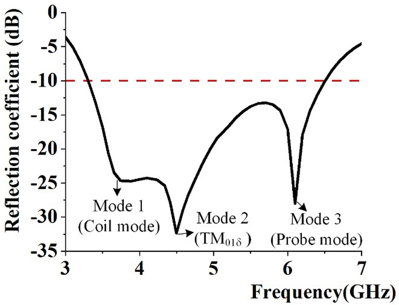
Figure 4: Simulated reflection coefficient of the CDRA.
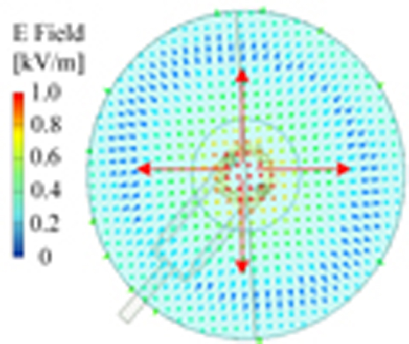
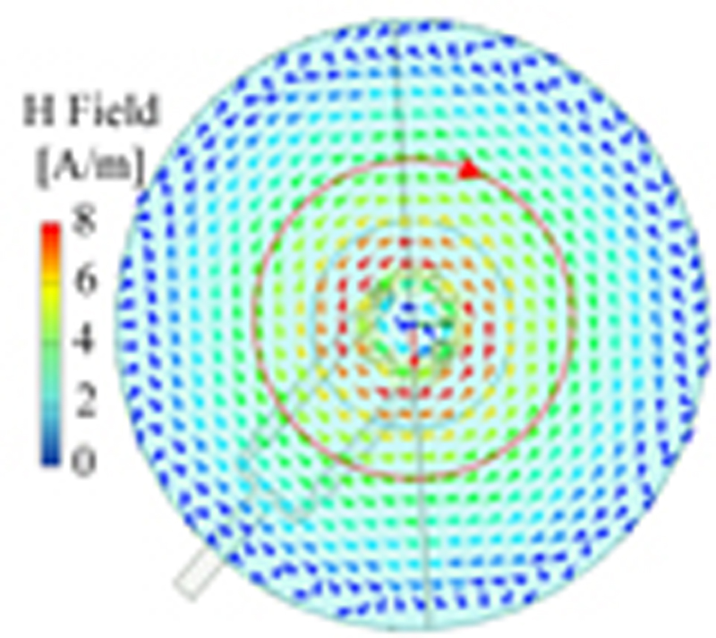
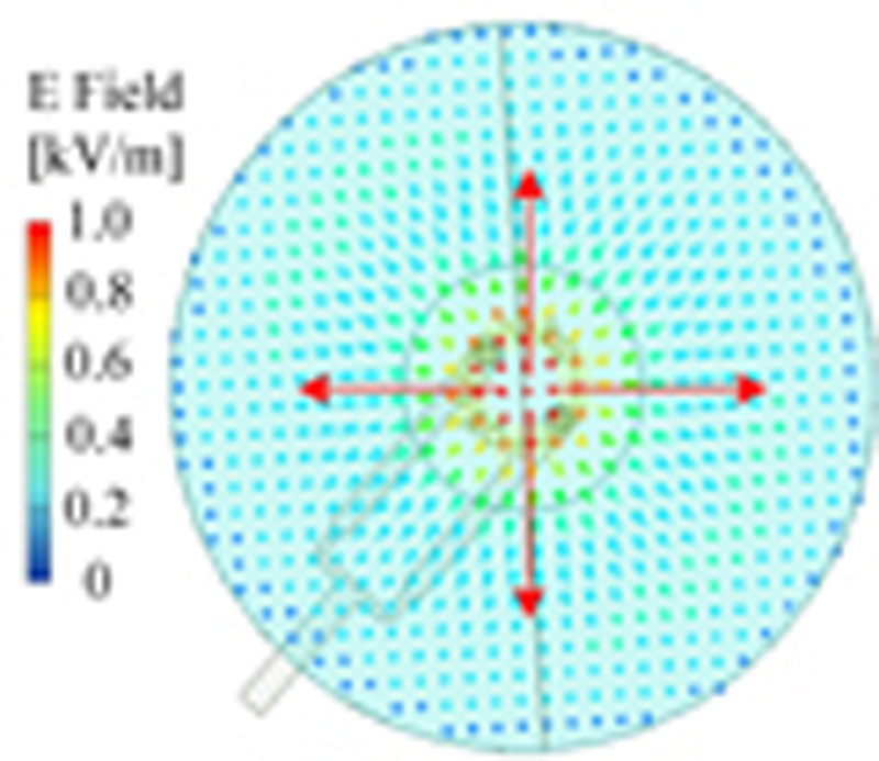
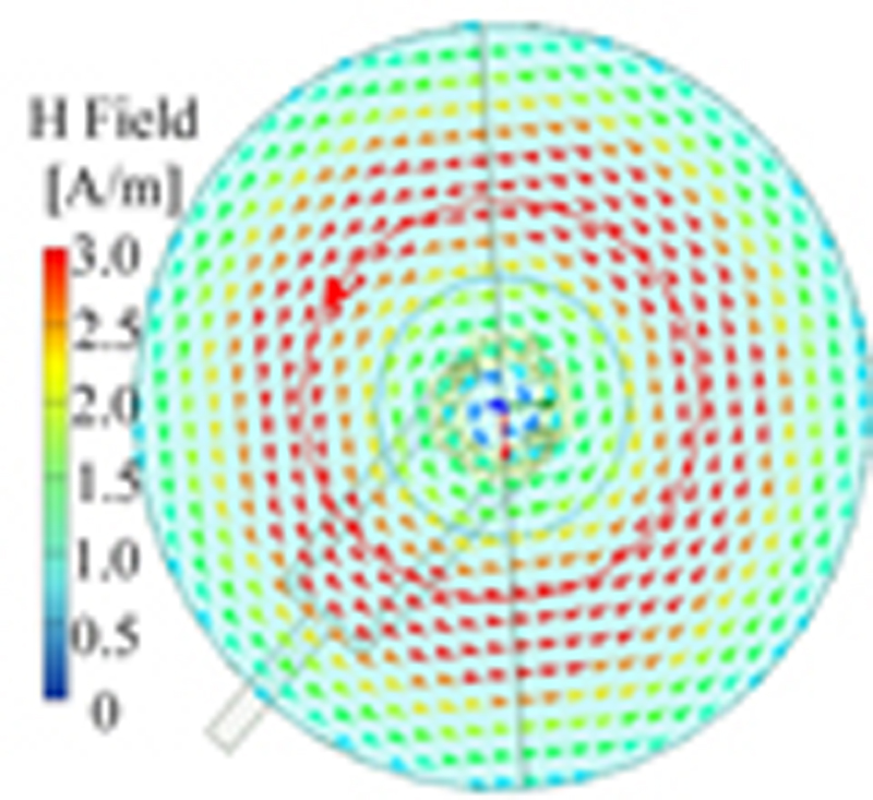
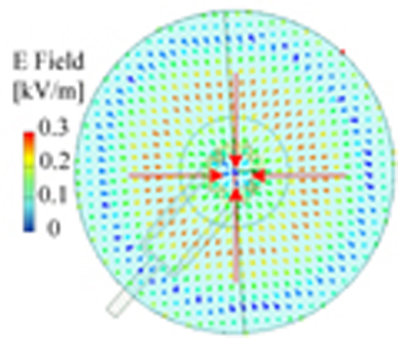
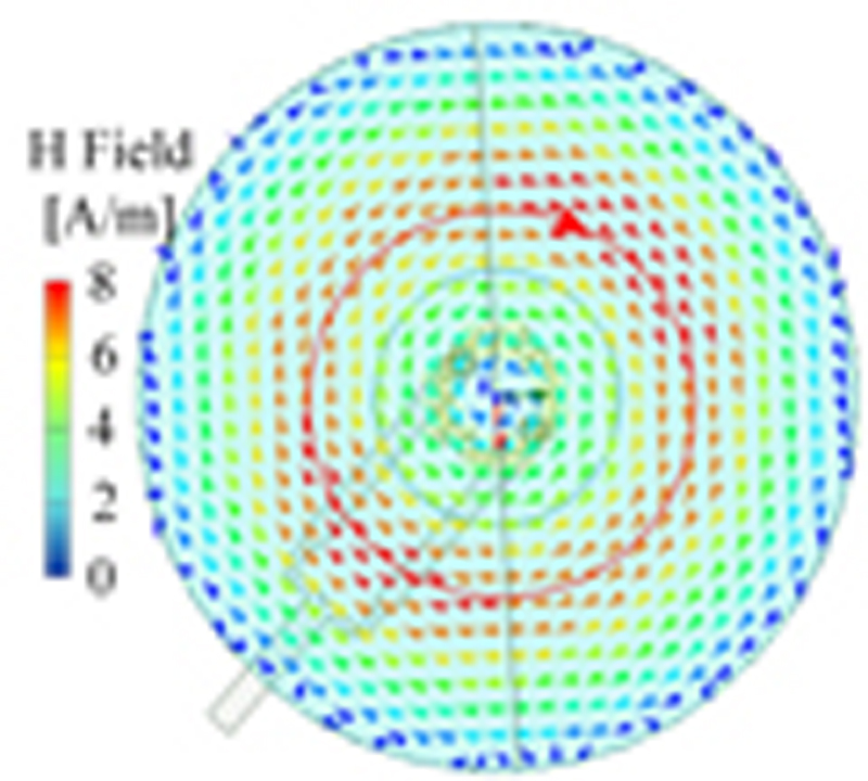
Figure 5: Simulated electric field (a), (c), and (e) and magnetic field (b), (d), and (f) at 3.65, 4.40, and 6.05 GHz, respectively.
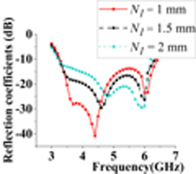
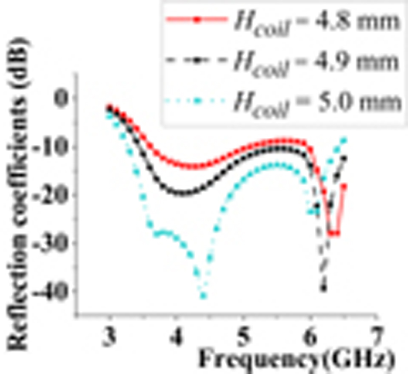
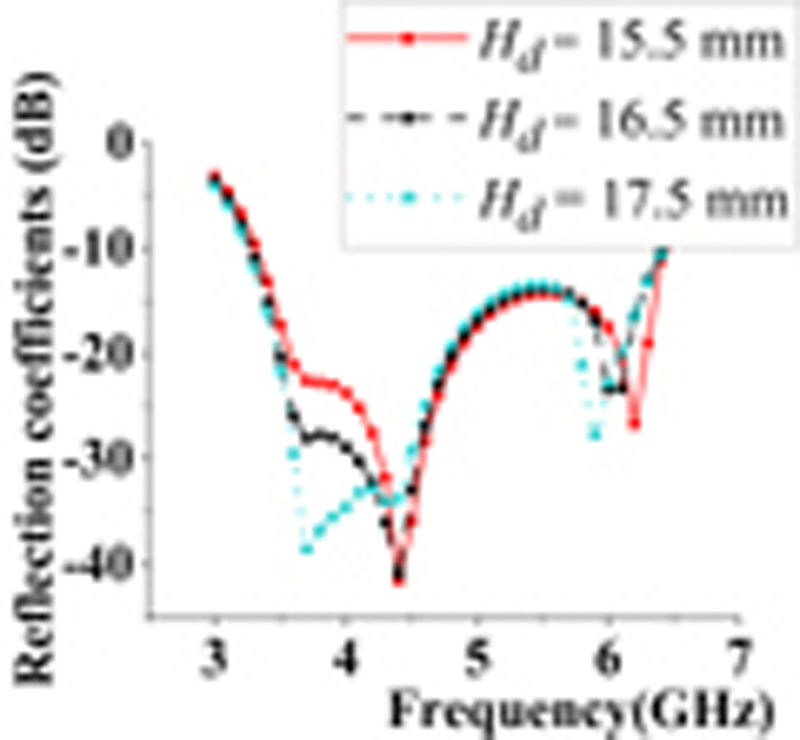
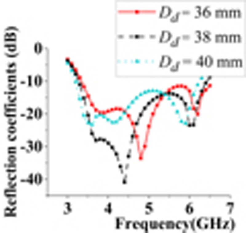
Figure 6: Reflection coefficients versus antenna parameters: (a) length of joint N, (b) coil height H, (c) dielectric height H, and (d) dielectric diameter D.
The simulated reflection coefficient of the CDRA is shown in Fig. 4 using the full-wave simulation software ANSYS HFSS. There are three distinct resonances within the operating bandwidth. Modes 1, 2, and 3 correspond to the coil, DR TM, and probe modes at 3.65, 4.40, and 6.05 GHz, respectively. Mode analysis will be explained in Section IV. The simulated magnetic and electric fields at these frequencies are shown in Fig. 5. The magnetic and electric fields of the coil and probe modes are similar to that of TM mode.
IV. PARAMETER STUDY
In this section, the antenna performances with different parameters are investigated by simulations. Firstly, the corresponding modes of three resonant frequencies are determined. Modes 1, 2, and 3 resonate at 3.65, 4.40, and 6.05 GHz, respectively. By exciting the cup DR with a single probe, the resonant frequency of the DR TM mode is 4.35 GHz, corresponding to the second resonant frequency. The reflection coefficients with different lengths of joint between two coils are shown in Fig. 6 (a). The length of the joint greatly influences the frequencies of modes 1 and 2, yet hardly affects the frequency of mode 3. Mode 3 corresponds to the monopole mode, and mode 1 corresponds to the coil mode.
Figure 6 (b) shows the reflection coefficients with different probe heights. As the probe gets longer, its corresponding resonant frequency gets lower. The probe height is the coil height from the ground plane, which decides the distance between the coil and the DR. Such height is related to the coupling between the DR and the equivalent magnetic-current loop, which obviously influences the impedance matching of the coil and DR TM modes. The reflection coefficients with different DR heights are shown in Fig. 6 (c). The probe resonant frequency is affected by the DR height. The resonant frequency of the monopole mode decreases as the DR height increases. The DR height has a negligible impact on the DR TM mode but a significant effect on the impedance matching of the coil mode. The DR diameter is related to the frequencies of all the modes. The frequencies of the modes with smaller DR diameters are higher. Their corresponding reflection coefficients are shown in Fig. 6 (d). As a result of the coupling among the CDRA, the magnetic-current loop, and the monopole, the resonant frequencies of the DR TM, coil, and monopole modes are interrelated.
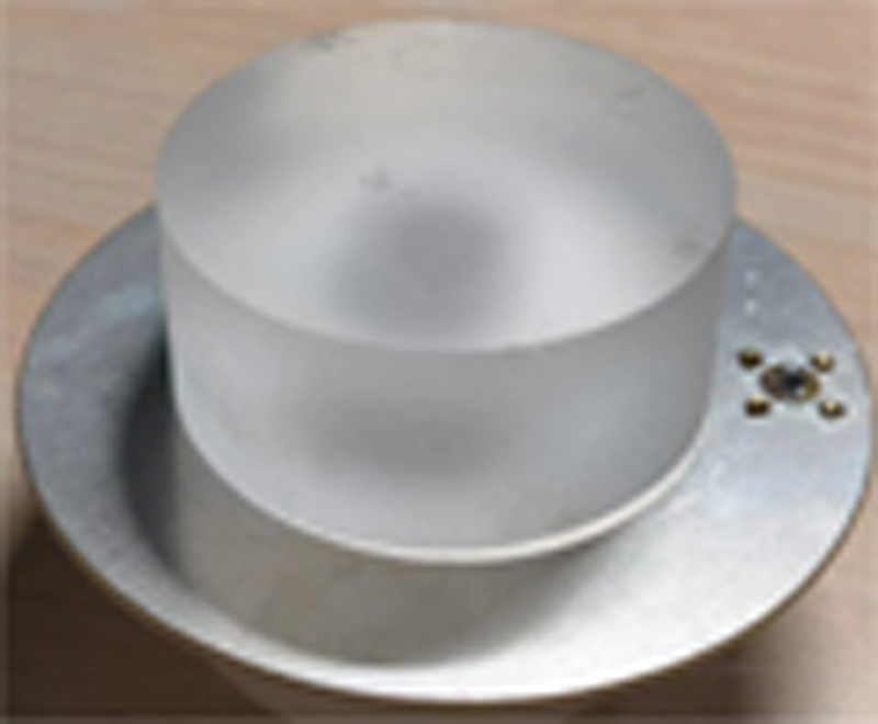
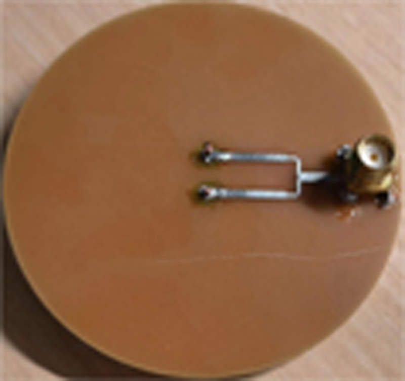
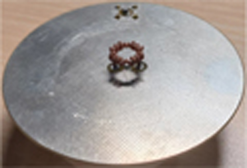
Figure 7: Prototypes of CDRA: (a) isometric view, (b) bottom view, and (c) coil.
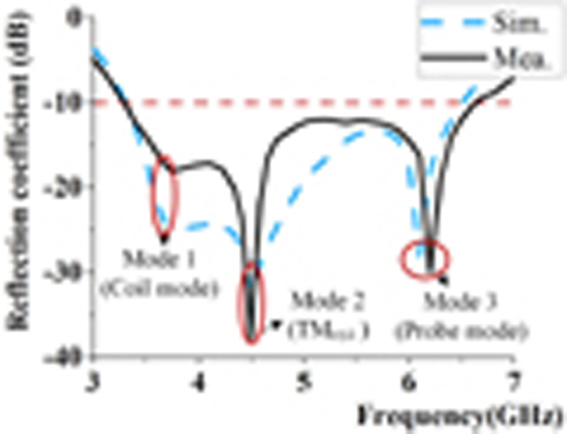
Figure 8: Simulated and measured reflection coefficients of the CDRA.
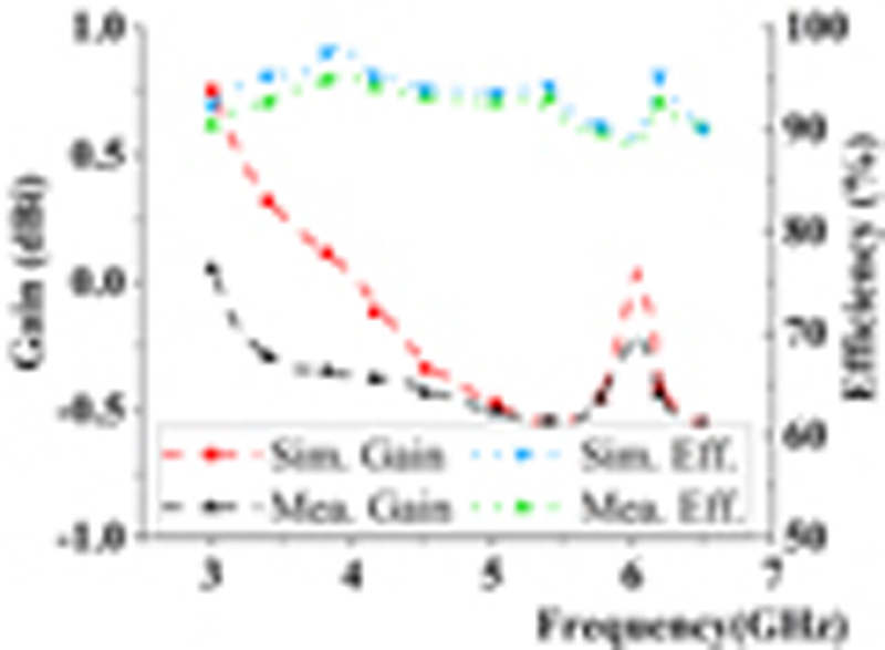
Figure 9: Simulated and measured gains and efficiencies of the CDRA.
V. RESULTS
A prototype of the CDRA is fabricated and measured as shown in Fig. 7. The CDRA is 37 mm 20 mm (0.61 0.32), while the cavity is 14.6 mm 5.6 mm to house the coil. The ground plane is 900 mm. The coil feeding structure is fabricated using the 3D-printing approach.
The simulated and measured reflection coefficients of the CDRA are shown in Fig. 8. There are three distinct resonances within the operating bandwidth. The measured bandwidth of the CDRA (with S -10 dB) is more than 67.7% (3.28-6.64 GHz), which is sufficient for 5 GHz WLAN bands. The measured reflection coefficient is wider than the simulated one because of extra loss in the prototype. The 3-D printed coil has a fabrication tolerance of 0.1 mm and a rough surface, which mainly influences the coil mode’s coupling.
Due to the limitation of the test equipment, the maximum test frequency is 6.5 GHz. The measured gain and efficiency are compared with the simulated in 3-6.5 GHz. As shown in Fig. 9, the simulated and measured efficiencies of the CDRA are better than 90% and 85%, respectively. The curves of gain are shown in Fig. 9. The gain variations of the CDRA are less than 1.5 dB in the operating band, which means the antenna has stable radiation patterns.
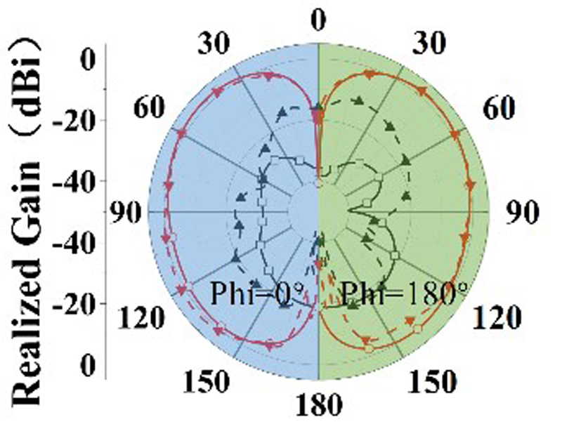
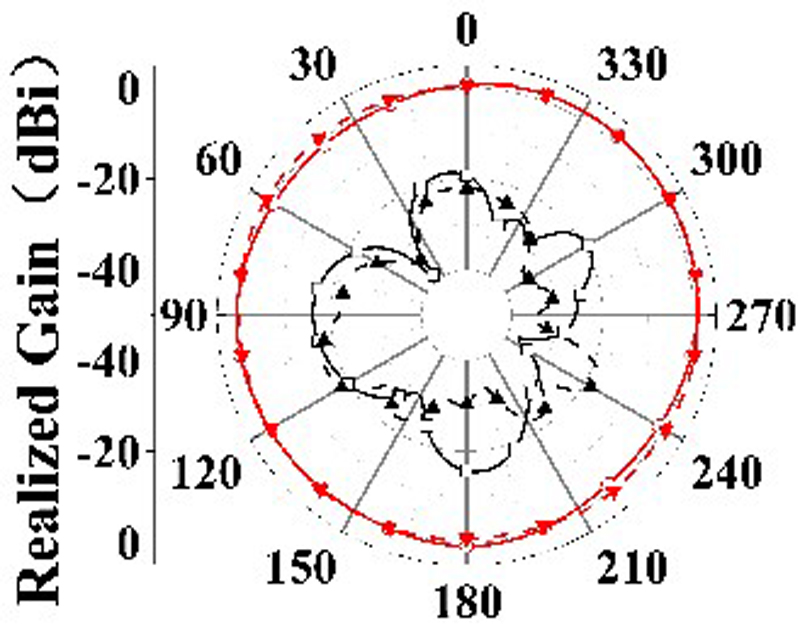
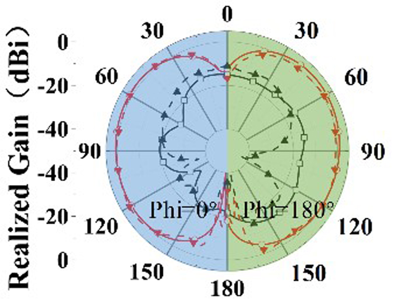
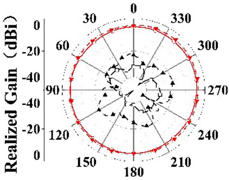
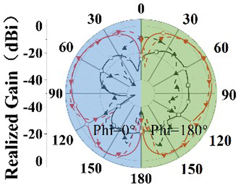
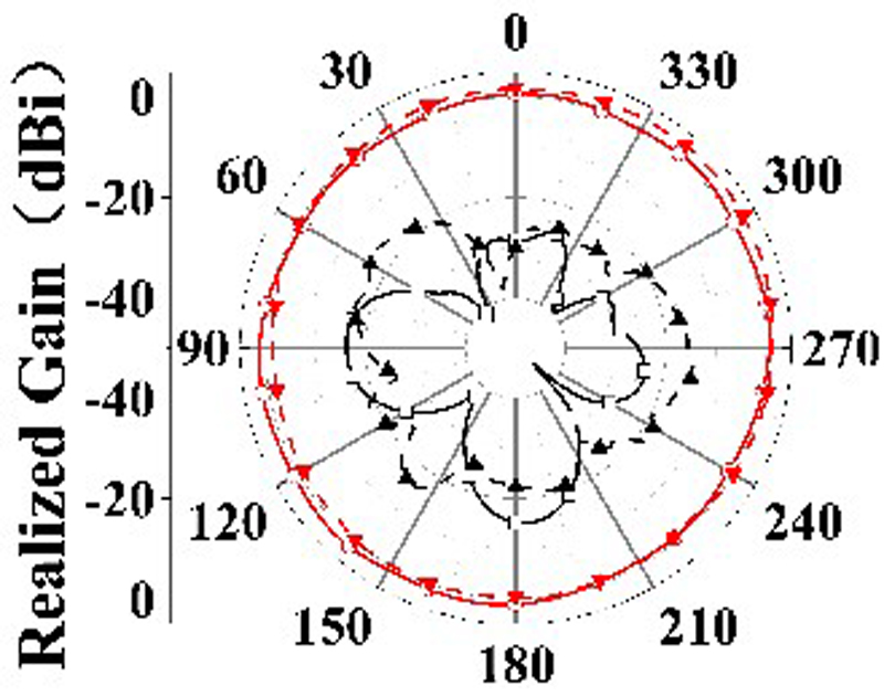
Figure 10: Simulated and measured radiation patterns in x-z plane (a), (c), and (e) and x-y plane (b), (d), and (f) at 3.65, 4.40, and 6.00 GHz, respectively.
Figure 10 shows the simulated and measured radiation patterns in the xz- and xy-plane at 3.65, 4.40, and 6.05 GHz. As can be seen, the CDRA maintains stable omnidirectional radiation patterns and a low cross-polarization level within the operating band. The measured radiation efficiency is better than 80%, and the simulated one is better than 85% across the impedance passband. The measurements and simulations are in reasonable agreement, with the differences caused by measurement perturbation and manufacturing tolerance.
VI. CONCLUSION
A modified coil feeding structure has been used to realize an omnidirectional wideband CDRA with three resonant modes (TM coil, and monopole modes). The modified coil has been formed by combining four coil segments and two probes, which could create an equivalent magnetic-current loop and a monopole simultaneously. Using the proper DR dimensions and feeding structure has excited the DR TM mode and two omnidirectional modes (i.e., coil and monopole modes) at neighboring frequencies to realize an omnidirectional antenna with a 67.7% measured bandwidth (3.28-6.64 GHz). The CDRA has a diameter of 0.61 and a height of 0.32 . The stable radiation patterns have been observed with high radiation efficiencies within the operating band.
REFERENCES
[1] K. W. Leung, E. H. Lim, and X. S. Fang, “Dielectric resonator antennas: From the basic to the aesthetic,” Proc. IEEE, vol. 100, no. 7, pp. 2181-2193, July 2012.
[2] K. W. Leung, Y. M. Pan, X. S. Fang, E. H. Lim, K.-M. Luk, and H. P. Chan, “Dual-function radiating glass for antennas and light covers Part I: Omnidirectional glass dielectric resonator antennas,” IEEE Trans. Antennas Propag., vol. 61, no. 2, pp. 578-586, Feb. 2013.
[3] N. Yang and K. W. Leung, “Size reduction of omnidirectional cylindrical dielectric resonator antenna using a magnetic aperture source,” IEEE Trans. Antennas Propag., vol. 68, no. 4, pp. 3248-3253, Apr. 2020.
[4] M. Zou and J. Pan, “Investigation of resonant modes in wideband hybrid omnidirectional rectangular dielectric resonator antenna,” IEEE Trans. Antennas Propag., vol. 63, no. 7, pp. 3272-3275, July 2015.
[5] C. A. Balanis, Antenna Theory: Analysis and Design, Hoboken, NJ: Wiley, 2005.
[6] J. Huang, “Circularly polarized conical patterns from circular microstrip antennas,” IEEE Trans. Antennas Propag., vol. 32, no. 9, pp. 991-994, Sep. 1984.
[7] D. M. Kokotoff, R. B. Waterhouse, and J. T. Aberle, “An annular ring coupled to a shorted patch,” IEEE Trans. Antennas Propag., vol. 45, no. 5, pp. 913-914, May 1997.
[8] H.-T. Chen, H.-D. Chen, and Y.-T. Cheng, “Full-wave analysis of the annular-ring loaded spherical-circular microstrip antenna,” IEEE Trans. Antennas Propag., vol. 45, no. 11, pp. 1581-1583, Nov. 1997.
[9] Y. Yu, J. Xiong, and H. Li, “Compact omni-directional circularly polarized antenna utilising bended dipoles and integrated baluns,” IET Microw. Antennas Propag., vol. 11, no. 10, pp. 1409-1414, July 2017.
[10] C. M. Wu, J. H. Choi, H. Lee, and T. Itoh, “Magnetic-current-loop-induced electric dipole antenna based on substrate integrated waveguide cavity,” IEEE Antennas Wireless Propag. Lett., vol. 13, pp. 519-522, Mar. 2014.
[11] A. Al-Zoubi, F. Yang, and A. Kishk, “A low-profile dual-band surface wave antenna with a monopole-like pattern,” IEEE Trans. Antennas Propag., vol. 55, no. 12, pp. 3404-3412, Dec. 2007.
[12] Y. Duan, M.-C. Tang, Z. Wu, Z. Zhang, D. Yi, and M. Li, “Omnidirectional-radiating, vertically polarized, wideband, electrically small filtenna,” IEEE Trans. Circuits Syst. II Exp. Briefs, vol. 70, no. 4, pp. 1380-1384, Apr. 2023.
[13] Y. Feng, L.-K. Zhang, J.-Y. Li, Y.-H. Yang, S.-G. Zhou, and X.-J. Yu, “A compact share-aperture antenna with pattern/polarization diversity for 5G sub-6G applications,” IEEE Trans. Circuits Syst. II Exp. Briefs, vol. 70, no. 3, pp. 954-958, Mar. 2023.
[14] D. D. Patil, K. S. Subramanian, and N. C. Pradhan, “3D-printed dual-band rectenna system for green IoT application,” IEEE Trans. Circuits Syst. II Exp. Briefs, vol. 70, no. 8, pp. 2864-2868, Aug. 2023.
[15] Y. M. Pan and K. W. Leung, “Wideband omnidirectional circularly polarized dielectric resonator antenna with parasitic strips,” IEEE Trans. Antennas Propag., vol. 60, no. 6, pp. 2992-2997, June 2012.
[16] C. Wang, Z. Han, H. Liu, P. Wen, L. Wang, and X. Zhang, “A novel single-feed filtering dielectric resonator antenna using slotline stepped-impedance resonator,” IEEE Trans. Circuits Syst. II Exp. Briefs, vol. 68, no. 11, pp. 3426-3430, Nov. 2021.
[17] D. Guha, B. Gupta, C. Kumar, and Y. M. M. Antar, “Segmented hemispherical DRA: New geometry characterized and investigated in multi-element composite forms for wideband antenna applications,” IEEE Trans. Antennas Propag., vol. 60, no. 3, pp. 1605-1610, Mar. 2012.
[18] S. H. Ong, A. A. Kishk, and A. W. Glisson, “Rod-ring dielectric resonator antenna,” Int. J. Rf. Microw. C. E., vol. 14, no. 5, pp. 441-446, Sep. 2004.
[19] S. Zheng, Z.-Y. Zhang, X. Chen, and A. A. Kishk, “Wideband monopole-like cup dielectric resonator antenna with coil feeding structure,” IEEE Trans. Antennas Propag., vol. 70, no. 8, pp. 7118-7123, Aug. 2022.
[20] N. Yang, K. W. Leung, K. Lu, and N. Wu, “Omnidirectional circularly polarized dielectric resonator antenna with logarithmic spiral slots in the ground,” IEEE Trans. Antennas Propag., vol. 65, no. 2, pp. 839-844, Feb. 2017.
[21] M. H. Seko and F. S. Correra, “Excitation of dielectric resonator antennas by loop coupling,” IEEE Antennas Wireless Propag. Lett., vol. 18, no. 4, pp. 656-658, Apr. 2019.
[22] W. Li, K. W. Leung, and N. Yang, “Omnidirectional dielectric resonator antenna with a planar feed for circular polarization diversity design,” IEEE Trans. Antennas Propag., vol. 66, no. 3, pp. 1189-1197, Mar. 2018.
[23] W. W. Li and K. W. Leung, “Omnidirectional circularly polarized dielectric resonator antenna with top-loaded Alford loop for pattern diversity design,” IEEE Trans. Antennas Propag., vol. 61, no. 8, pp. 4246-4256, Aug. 2013.
[24] Z.-X. Xia, K. W. Leung, and K. Lu, “3-D-printed wideband multi-ring dielectric resonator antenna,” IEEE Antennas Wireless Propag. Lett., vol. 18, no. 10, pp. 2110-2114, Oct. 2019.
[25] H. Tang, L. Wu, D. Ma, H. Li, J. Huang, X. Deng, J. Zhou, and J. Shi, “Wideband filtering omnidirectional substrate-integrated dielectric resonator antenna covering Ku band,” IEEE Antennas Wireless Propag. Lett., vol. 22, no. 7, pp. 1746-1750, July 2023.
[26] X. S. Fang, L. P. Weng, and Z. Fan, “Design of the wideband and low-height omnidirectional cylindrical dielectric resonator antenna using arced-apertures feeding,” IEEE Access, vol. 11, pp. 20128-20135, 2023.
[27] M. Lapierre, Y. M. M. Antar, A. Ittipiboon, and A. Petosa, “Ultra-wideband monopole/dielectric resonator antenna,” IEEE Microw. Wireless Compon. Lett., vol. 15, no. 1, pp. 7-9, Jan. 2005.
[28] K. S. Ryu and A. A. Kishk, “UWB dielectric resonator antenna having consistent omnidirectional pattern and low cross-polarization characteristics,” IEEE Trans. Antennas Propag., vol. 59, no. 4, pp. 1403-1408, Apr. 2011.
[29] D. Guha, B. Gupta, and Y. Antar, “Hybrid monopole-DRAs using hemispherical/conical-shaped dielectric ring resonators: Improved ultrawideband designs,” IEEE Trans. Antennas Propag., vol. 60, no. 1, pp. 393-398, Jan. 2012.
[30] C. Ozzaim, F. Ustuner, and N. Tarim, “Stacked conical ring dielectric resonator antenna excited by a monopole for improved ultrawide bandwidth,” IEEE Trans. Antennas Propag., vol. 61, no. 3, pp. 1435-1438, Mar. 2013.
BIOGRAPHIES

Shuxin Zheng received the B.Sc. degree in electronics and information engineering from Xi’an Jiaotong University, Xi’an, China, in 2021, where she is currently pursuing the Ph.D. degree in electronics science and technology from Xi’an Jiaotong University, Xi’an. Her current research direction is antenna design.

Nan Yang received the B.Sc. and M.Eng. degrees in electronic engineering from Zhejiang University (ZJU), Hangzhou, China, in 2008 and 2012, respectively, and the Ph.D. degree from the City University of Hong Kong, Hong Kong, in 2016. He was a Post-Doctoral Fellow with the City University of Hong Kong from 2016 to 2020. He is currently an Associate Professor with the School of Electronics and Information Technology (School of Microelectronics), Sun Yat-sen University (SYSU), Guangzhou, China. His current research interests include dielectric resonator antennas, lens antennas, multiple-input-multiple-output (MIMO) antennas, transparent antennas, and microwave and millimeter-wave circuits.

Xiaoming Chen received the B.Sc. degree in electrical engineering from Northwestern Polytechnical University, Xi’an, China, in 2006, and M.Sc. and PhD degrees in electrical engineering from Chalmers University of Technology, Gothenburg, Sweden, in 2007 and 2012, respectively. From 2013 to 2014, he was a postdoctoral researcher at the same University. From 2014 to 2017, he was with Qamcom Research & Technology AB, Gothenburg, Sweden, Since 2017, he has been a professor at Xi’an Jiaotong University, Xi’an, China. His research areas include 5G multi-antenna techniques, over-the-air (OTA) testing, and reverberation chambers.

Zhen-Yuan Zhang received the B.S. degree in electronic science and engineering from the Nanjing University of Posts and Communications, Nanjing, China, in 2011, and the M.S. and Ph.D. degrees from The Chinese University of Hong Kong, Hong Kong, in 2013 and 2019, respectively. Currently, he is a Post-Doctoral Fellow with the Southern University of Science and Technology, Shenzhen, China. His current research interests include circularly polarized antenna design, wideband base station antenna design, and antenna break decoupling techniques.

Bingyi Qian received the B.S. degree in electronics and information engineering from Xidian University, Xi’an, China, in 2020, where he is currently pursuing the Ph.D. degree in electronics science and technology from Xi’an Jiaotong University, Xi’an. His current research interests include microstrip antenna design, mutual coupling reduction and 5G mobile antennas.

Ahmed A. Kishk received the Ph.D. degree from the University of Manitoba, Winnipeg, MB, Canada, in 1986. In 1986, he joined the University of Mississippi, Oxford, MS, USA, first as an Assistant Professor and then a Professor. Since 2011, he has been a Professor and a Tier 1 Canada Research Chair in advanced antenna systems with Concordia University, Montreal, QC, Canada. He has published over 340 refereed journal articles and 450 conference papers. He is a co-author of four books and several book chapters, and an editor of three books. His research interest includes millimeter-wave antennas, beamforming networks, dielectric resonator antennas, microstrip antennas, and electromagnetic band gap (EBG).
ACES JOURNAL, Vol. 39, No. 10, 908–915
doi: 10.13052/2024.ACES.J.391009
© 2024 River Publishers