Optimization of PMSM for EV based on Vibration and Noise Suppression
Mingwei Zhao1,2, Xiangyu Wang2, Lijun Liu1,2*, Xiaowei Tu1, and Qinghua Yang1*
1School of Electromechanical Engineering and Automation
Shanghai University, Shanghai, 200444, China
xznu_zmw@163.com, xznu_llj@163.com, yqh_lw@163.com
2School of Electrical Engineering and Automation
Jiangsu Normal University, Xuzhou, 221116, China
wxyinjsnu@163.com, tuxiaowei@shu.edu.cn
*Corresponding Author
Submitted On: September 18, 2023; Accepted On: February 4, 2024
ABSTRACT
The key to the suppression of vibration and noise for PMSM is the optimization of electromagnetic excitation force. The method of motor body optimization can effectively reduce the radial excitation force of the motor, so as to suppress the vibration and noise of the motor. Firstly, the stator structure of the motor is optimized with V-shape skew slot based on the analytical modeling of the radial electromagnetic excitation force of the motor. Then, the structural parameters of the motor that affect the electromagnetic excitation force of the motor are determined, and the average torque, torque ripple and radial electromagnetic excitation force generated by tangential electromagnetic excitation force are taken as the optimization objectives. The sensitivity analysis and classification of the structural parameters of the motor are carried out. The multi-objective genetic algorithm and response surface method are combined to optimize the structural parameters of the motor. Finally, the finite element analysis, modal analysis, multi-speed vibration and noise analysis of the optimized motor are done. The performance comparisons before and after optimization have proved that the peak of equivalent sound power level have decreased by 8.65% after the optimization of V-shaped skewed slot structure. After the optimization of structural parameters, the power level of permanent magnet synchronous motor has been reduced by 9.22%. For the vibration noise caused by resonance and the main frequency of vibration noise harmonics, the suppression effects are also better than those of V-shape skewed slots optimization, and the ERPL values are reduced by 9.22% and 10.12%, respectively, in two cases. The results show that the vibration and noise of permanent magnet synchronous motor are effectively suppressed.
Index Terms: genetic optimization algorithm, multi-objective hierarchical optimization, PMSM, skewed slots optimization, vibration and noise suppression.
I. INTRODUCTION
The problem of Noise, Vibration, Harshness (NVH) of vehicles is one of the issues of great concern to major new energy vehicle manufacturers. The NVH problem involves all parts of the vehicle, but as a new energy electric vehicle, the motor is the core component of the power system and the most important incentive source of NVH. The interior permanent magnet synchronous motor (IPMSM) has the advantages of small size, light weight, high efficiency and high power density, and the electric drive system with it as the core has the characteristics of excellent comprehensive performance indicators. Therefore, vibration and noise suppression of the IPMSM is one of the hot spots in the field of electric vehicle research at present [1].
Electromagnetic stress and modal parameters are two key factors affecting electromagnetic vibration noise of motor. Electromagnetic waves include tangential and radial electromagnetic waves, and tangential force waves can cause torque pulsation, resulting in vibration noise [2]. The radial electromagnetic wave will cause periodic deformation of the motor core and cause vibration, which is the main source of vibration noise [3]. The influence of motor mode and radial electromagnetic force on noise was studied in [4–5], showing that larger vibration noise would be caused when the frequency of radial electromagnetic wave was close to the mode frequency.
The main method to suppress the electromagnetic vibration noise of PMSM is to optimize the motor body at present. It can be divided into two categories. One is to suppress the noise by optimizing the air gap shape, permanent magnet structure and structure of stator and rotor. In [6], segmented skew pole optimization was carried out for the motor, but only for a step skew pole optimization, and no further optimization was carried out. The IPMSM using single and double permanent magnet rotors was analyzed, which showed that the electromagnetic noise performance of double permanent magnet yoke was better in [7]. In [8], a virtual tooth structure between poles was used to weaken the six frequency vibration noise of the surface mounted permanent magnet motor, and the third, fifth and seventh harmonics were weakened at the same time, but the weakening effect on other harmonics was missing. NVH could be optimized by means of stator tooth chamfering [9]. In [10], a method was proposed to cut auxiliary slots in the top of the stator teeth and to optimize the parameters of the slots. In [11], the magnetic amplitude was reduced to near the resonant frequency by optimizing the slot width. However, only the optimization of radial electromagnetic excitation force was considered, and the tangential electromagnetic torque was not analyzed in [7–11].
The other is to reduce the vibration noise of PMSM from the structural parameters. In [12], a three-dimensional finite element analysis method was proposed to analyze the influence of parameters of stator and rotor on the resonant frequencies of reducing the total sound power, so as to avoid the occurrence of resonance phenomenon. However, only single-stage optimization of structural parameters was carried out, which was inferior to hierarchical optimization in terms of optimization efficiency and optimization fitness. In [13], the electromagnetic force density of the air gap is analyzed and derived, and the minimum peak value of the electromagnetic force density distributed along the air gap circumference of the motor was taken as the optimization objective, and the optimization values of the stator skew-slot shape, magnetic steel size and air gap size were determined based on the sensitivity analysis results, but only a single objective optimization was carried out without comprehensive analysis of multiple objectives. As the complexity of motor structure increases, it is proposed that the randomness and global nature of multiple samples in optimization have a great impact on the global nature of optimization results, so a multi-objective optimization algorithm is adopted to comprehensively consider the optimization effect of multiple objectives [14]. In [15], the multi-objective optimization of the torque ripple and the peak value of radial electromagnetic force distributed along the circumference of the air gap was carried out for the structural parameters of the motor, and the parameters were graded according to the sensitivity analysis results, so as to obtain a better optimization effect. However, only the angle of the step skewed slots was optimized as a structural parameter.
A 40 kW 48-slot 8-pole IPMSM are taken as an example in this paper. Two aspects of optimization are adopted at the same time based on the analytical modeling of the radial electromagnetic force of the motor. On the one hand, the skewed slot structure optimization is carried out, and the effects of various skewed slot optimization structures are compared and analyzed, and the best skewed slots structure scheme is selected. On the other hand, multi-objective optimization of motor structure parameters affecting electromagnetic vibration noise is carried out with the objectives of minimum radial electromagnetic force peak, minimum torque ripple and maximum average torque. Based on the sensitivity analysis of motor structure parameters, the motor structure parameters are divided into three levels: high sensitivity parameters, low sensitivity parameters and irrelevant parameters. The multi-objective genetic algorithm and response surface method are combined to optimize the high and low structural parameters of the motor. The effectiveness of the proposed method is verified by comparing the radial electromagnetic force space harmonics, torque pulsation and equivalent radiated power level (ERPL) of the IPMSM before and after optimization.
II. RADIAL ELECTROMAGNETIC FORCE THEORY OF IPMSM
A. Radial electromagnetic excitation stress model of IPMSM
The radial electromagnetic force, the main source of electromagnetic vibration and noise, is mainly generatedby a series of stator and rotor magnetic field harmonics [16]. The magnetic field established by synchronous motor armature reaction magnetomotive force is:
| (1) |
where is the initial phase, is the frequency of three-phase current in the stator winding, and is the -order harmonic magnetic density amplitude of the armature reaction magnetic field, and can be expressed as:
| (2) |
where is the air gap magnetic density for no load, considering the salient pole effect of the rotor, is the per-unit value of direct axis armature reaction reactance, is per-unit value of load current, is the number of pole pairs of the fundamental wave of the stator magnetomotive force (number of motor rotor pole pairs), and the order of harmonics , .
The magnetic field established by the rotor magnetomotive force of the synchronous motor, that is, the no-load airgap magnetic field is:
| (3) |
where is the magnetic density amplitude of the -order harmonic of the main pole magnetic field under load.
| (4) |
where is the magnetic density amplitude of the fundamental wave, is the polar arc coefficient, and is the number of stator slots. The first term in (3) is the magnetic field generated by the rotor magnetomotive force in the uniform air gap, the second term is the additional magnetic field caused by the stator slots.
When the synchronous motor is running under load, the air gap magnetic field is the sum of the armature reaction magnetic field and the rotor magnetomotive force magnetic field, that is:
| (5) | ||||
According to Maxwell stress tensor, the radial force under load is:
| (6) | ||||
After expansion of (6), the term that has a greater impact on electromagnetic noise is retained, so (6) can be simplified as:
| (7) |
The orders of each force wave are , , and . , and can be expressed as:
| (8) |
where .
The first item in (7) is the force waves generated by the alone action of the same order harmonics of the rotor magnetic field itself. The second term is the force waves generated by the combined modulation of different order harmonics of the rotor magnetic field itself. The third and fourth terms are the force waves generated by the interaction between the stator and rotor harmonic magnetic fields.
B. Force waves that may cause strong vibration noise of the motor
When the motor is running under load, whether a series of force waves included by radial force can cause strong vibration and noise of the motor depends on the three elements of force wave, including size, order and change frequency [17]. It can be seen from (8) that the frequency of radial force wave during load operation of synchronous motor is an integer multiple of twice the frequency of power supply, that is:
| (9) |
where is the power supply frequency, and .
Accordingly, the vibration frequency caused by radial force wave is also an integer multiple of twice the power supply frequency . Relative to the rotor rotation frequency, the frequency of the radial force wave is the times the rotor rotation frequency, that is, the time order of the radial force wave is order, namely, the number of vibrations of the rotor rotating a full circle is an integer multiple of the number of poles. In addition, according to each order of radial force wave in (6), the lowest non-zero order of spatial force wave of synchronous motor is during load operation.
The radial force waves that need to be paid attention to when the synchronous motor is loaded are as follows:
(1) Radial force waves with frequency produced by the main wave magnetic field
Namely, the first force wave in (7), when , corresponds to the radial force wave caused by the main wave magnetic field (harmonic order ) with the pole pairs .
(2) Lower order force wave generated by the interaction between the first order tooth-harmonic magnetic field of stator and the -order harmonic magnetic field of rotor
When the synchronous motor is running without load, the radial force wave generated by the interaction between the -order harmonic of the rotor main pole magnetic field with the pole number and frequency and the first order tooth-harmonic of the rotor main wave with the pole number and frequency , is the main source of electromagnetic vibration noise which corresponds to the radial force wave of the 2nd term of (7) when .
When or is the integer closest to , the number of slots per pole, the orders of two lower order dangerous force waves, i.e., or , appears as a minimum.
In the case of the synchronous motor load operation, the radial force wave generated by the interaction between the stator first order teeth harmonic magnetic field of the armature winding and the -order harmonic magnetic field of the rotor is the 3rd term of (7) when .
When or is the integer closest to , the number of slots per pole, the 3rd term in (7) contains two low-order dangerous force waves. The minimum value of the orders of these two force waves, i.e., or , is most likely to cause electromagnetic vibration noise of synchronous motor load.
(3) Radial force wave generated by the interaction between the stator and the rotor harmonic magnetic field
When the synchronous motor is running under load, the radial force wave generated by the interaction between the stator -order harmonic magnetic field and the rotor -order harmonic magnetic field is the 3rd term of (7), and the orders of dangerous force waves with lower order are:
| (10) |
where is the denominator of the number of slots of per pole per phase.
When is closest to or , the minimum value of appears, and the generated force wave is most likely to cause electromagnetic vibration noise of the synchronous motor load.
(4) Radial force waves generated by interaction between stator tooth-harmonic magnetic field and permanent magnet rotor field
The 4th term of (7) contains the lower order dangerous force waves generated by interaction between stator tooth-harmonic magnetic field and permanent magnet rotor field and the orders of dangerous force waves are, respectively:
| (11) |
and
| (12) |
For the integer slot winding, when and are closest, or and are closest, appears the minimum value, and the generated force wave is most likely to cause the electromagnetic vibration noise of the synchronous motor load.
Table 1: Operating parameters of motor
| Parameters | Value | Parameters | Value |
|---|---|---|---|
| Rated power/kW | 40 | Rated speed/Maximum speed/rpm | 3000/6000 |
| Rated torque/Maximum torque/N.m | 127.3/318.3 | Efficiency (at rated speed) | 85% |
| Rated voltage/V | 126 | Operating temperature/cel | 120 |
| Material of iron core | DW310_35 | Material of magnetic steel | NdFe35 |
Table 2: Structure parameter of motor
| Parameters | Value | Parameters | Value |
|---|---|---|---|
| 220 | 142 | ||
| 144 | 48 | ||
| 7.5 | 0.73 | ||
| 0.5 | 1.5 | ||
| 0.5 | 10 | ||
| 23 | 5 | ||
| 2.5 | 149 | ||
| 5.2 | 4.6466 | ||
| 7.5 | 37.6638 |
III. NUMERICAL ANALYSIS OF RADIAL ELECTROMAGNETIC FORCE
A. Initialization design of IPMSM
In order to reduce the electromagnetic noise of the motor, a 48-slot 8-pole IPMSM is selected. The working parameters of the motor are shown in Table 1, including rated power, rated speed and rated voltage. Motor structure parameters are shown in Table 2. They are stator outer diameter , stator inner diameter , slot Angle , slot height , slot shoulder height , slot width height , slot width , slot center width , slot bottom width , rotor outer diameter, rotor inner diameter , pole arc coefficient , magnetic bridge thickness , cross axis magnetic path width , cross axis magnetic path height , magnetic steel thickness , core length , and the distance between rotating shaft and magnetic steel , respectively. The motor model is established based on the parameters above, and the cross section and main structural parameters of the motor are shown in Fig. 1. The stator slot adopts a pear-shaped slot, and its structure and main parameters are shown in Fig. 2.
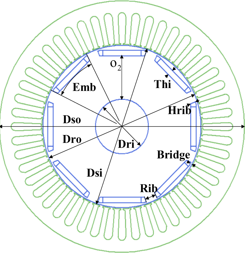
Figure 1: Cross-section of the motor model.
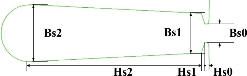
Figure 2: Stator groove structure of motor.
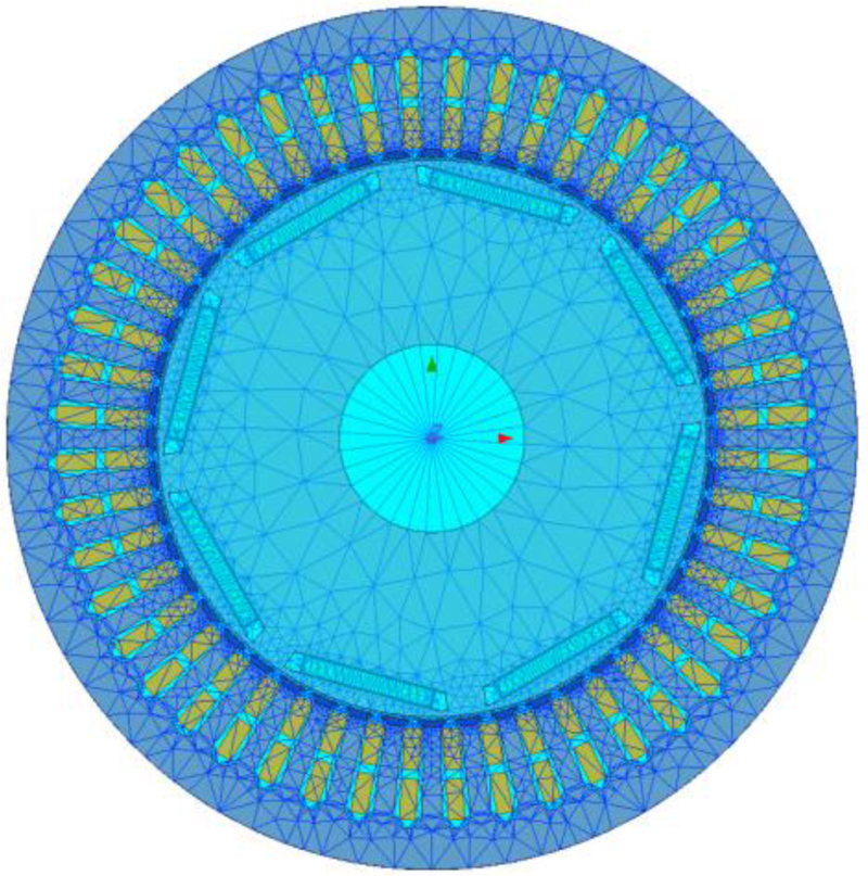
Figure 3: Maxwell 2D finite element model of motor with mesh division.
The 2D finite element model of the motor is shown in Fig. 3. The rotation region and boundary of the model are set, respectively. In order to improve the running accuracy of the model, the model is discretized by mesh generation and the finite element solution is carried out. The current source excitation of the motor finite element model is .
The distribution of magnetic induction intensity and magnetic field line of the motor are shown in Fig. 4, which shows the density of magnetic field line A at each position of the stator and rotor and the magnetic induction intensity at different positions at a certain time. It can be seen more intuitively that the magnetic field line always passes along the path with small magnetoresistance.
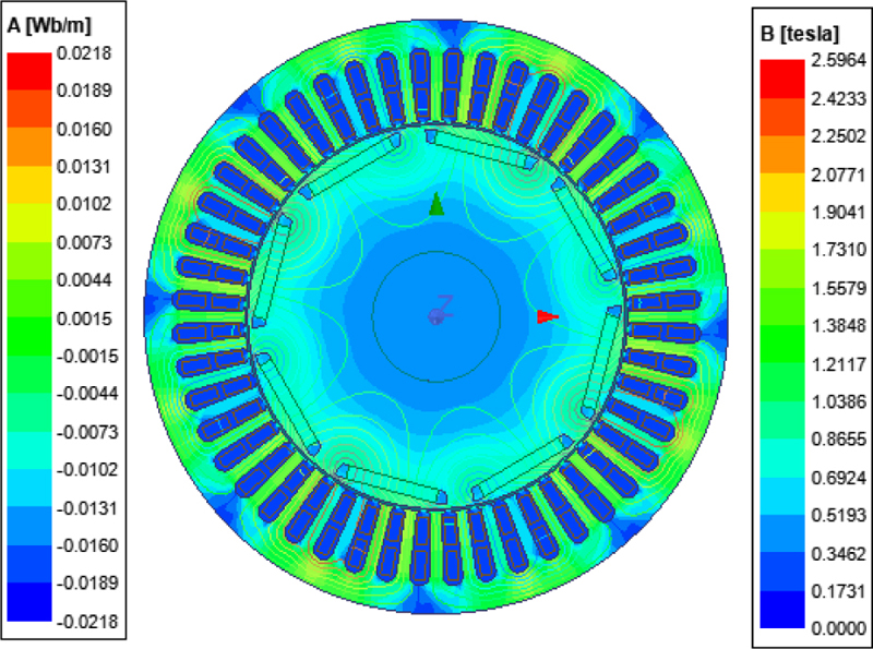
Figure 4: Distribution of magnetic induction intensity and field line of motor.
B. Calculation and analysis of radial excitation force
The Cartesian coordinate system is used to simulate and solve the motor, and then the field calculator is adopted to post-process the results. The radial magnetic induction intensity is converted according to the following formula:
| (13) |
where is the angle between the x axis and the column coordinate, and are the components of the magnetic induction intensity in the direction of x axis and y axis, respectively.
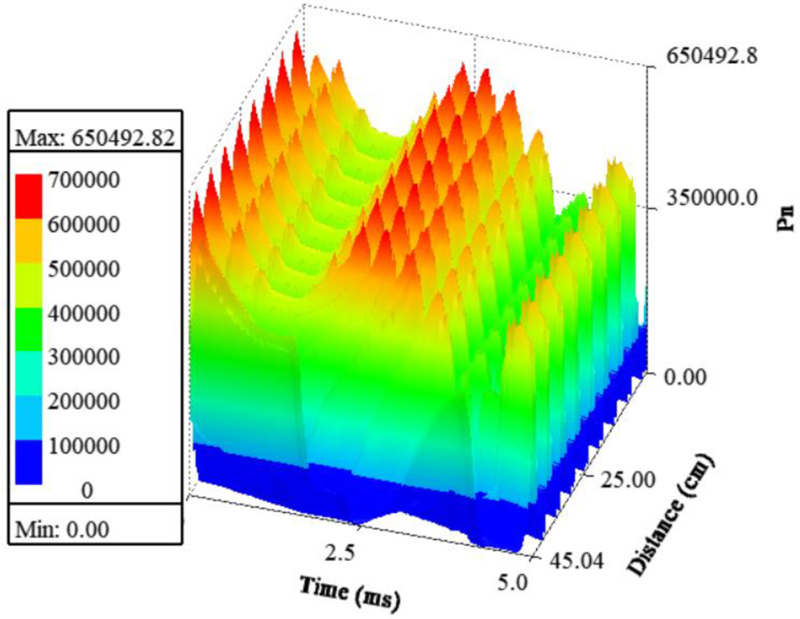
Figure 5: 3D diagram of radial electromagnetic stress with time and space.
The variation of radial electromagnetic waves along the air gap circumference of the motor model with time and space is shown in Fig. 5. Due to the influence of stator teeth and slots, the radial electromagnetic force changes periodically with the space position, and it is also a periodic function of time. Therefore, the harmonic response analysis of the radial electromagnetic force can further analyze its influence on electromagnetic vibration.
IV. OPTIMIZATION OF SKEWED SLOTS STRUCTURE OF IPMSM
A. Skewed slots optimization method
(1) Step skewed slots
When the stator slots are skewed, the tooth-harmonics of the stator and rotor magnetic fields are weakened, and the radial force wave has phase displacement along the axial direction. Therefore, the average radial force along the axial direction is reduced, reducing the electromagnetic vibration and noise of the motor effectively [18]. The skewed slots structure of stator is shown in Fig. 6. The relevant parameters are identified in the figure, where is the identification of the stator axial direction, is the skewed slots distance, i.e., arc length, R is the outer radius of the stator, is the angle of the skewed slots, and is the length of stator core.
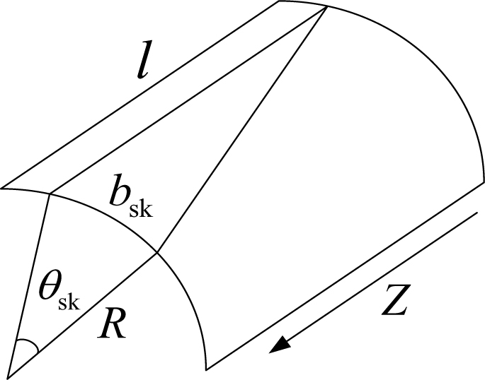
Figure 6: Schematic diagram of skewed slot structure of stator.
When the stator slots are skewed, and the rotor slots are straight, the radial exciting force generated by the interaction between the stator -order harmonic magnetic field and the -order harmonic magnetic field generated by the fundamental wave current of the rotor is integrated along the direction of core length and then the average radial force, that is, the axial zero-order vibration radial force , can be expressed as:
| (14) | ||||
where refers to the amplitude of 0-order radial force when no skewed slots.
The skewed slots coefficient is defined as:
| (15) |
where is the slot distance of stator.
The theoretical analysis shows that the average amplitude of the 0-order radial force wave along the axial direction is:
| (16) |
In addition, due to the role of the skewed slots, the skewed slots coefficient of the tooth-harmonics, that is, the most important magnetic field harmonics in the motor, is very small or even 0, which greatly reduces the vibration noise caused by tooth-harmonics.
(2) V-shape skewed slot
Although the unidirectional skewed slots can reduce the vibration noise caused by tooth-harmonics, it will cause transverse current and torsional moment, thus increasing the additional loss, generating additional axial force and torsional vibration [18]. In order to avoid the above side effects, V-shape skewed slots measures can also be used. Its structure is characterized by dividing the stator into two halves along the axial length, each half is equivalent to a skewed slots stator, and two parts are twisted in the opposite directions, forming a ”V” shape, as shown in Fig. 7. The relative tooth-harmonics of the two parts of the stator are just in reverse phase, and the harmonic torque generated by the first-order and odd-order tooth-harmonics in the two stator segments cancels each other, which is more conducive to reducing the vibration and noise of the motor.
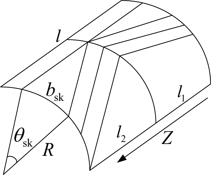
Figure 7: Diagram of V-shape skewed slots structure.
B. Motor skewed slots optimization design
The skewed slots are set based on the initial design of motor model. The structure of the segment skewed slots are adopted, the motor stator is divided into five sections, and two skewed slots schemes of step and V-shape are used, respectively. The parameter settings of each scheme are shown in Table 3.
Table 3: Parameters settings of skewed slots
| Mode of Skewed Slots | Step Skewed Slots | V-shape Skewed Slots |
|---|---|---|
| Number of segments | 5 | 5 |
| Best equivalent skewed slots angle | 7.5 | 7.5 |
| Angle set actually | 6 | 5 |
| Twist angle of segment 1 | -3 | 2 |
| Twist angle of segment 2 | 1.5 | 0.5 |
| Twist angle of segment 3 | 0 | -3 |
| Twist angle of segment 4 | 1.5 | 0.5 |
| Twist angle of segment 5 | 3 | 2 |
C. Evaluation index of motor skewed slots optimization scheme
The peak value of radial electromagnetic stress distributed along the circumference of air gap under different skewed slots schemes is taken as the evaluation index. The smaller is, the smaller vibration noise caused by the radial force is, and the better the optimization effect.
The expression of radial electromagnetic stress distribution along the arc of the center of the air gap is:
| (17) |
where is the arc radius of the center of the air gap, which can be expressed as:
| (18) |
where is the inner diameter of the stator and is the length of the air gap.
So the peak value of can be denoted by:
| (19) |
D. Optimization effect comparison of different skewed slots schemes
Figure 8 shows the distribution of stator in different segments of the motor under different skewed slots schemes. When the stator has no skewed slots, is 567578.7660N, and the average of the five-segment stator with step slots is 565186.2524N, which decreases 2392.5136N compared with that without skewed slots. The average of the five-segment stator with a V-shaped skewed slots is 552646.8741N, which decreases 14931.8919N compared with that without skewed slots. Therefore, the improvement degree of electromagnetic noise of IPMSM with stator V-shaped skewed slots structure is higher than that of the step skewed slots.
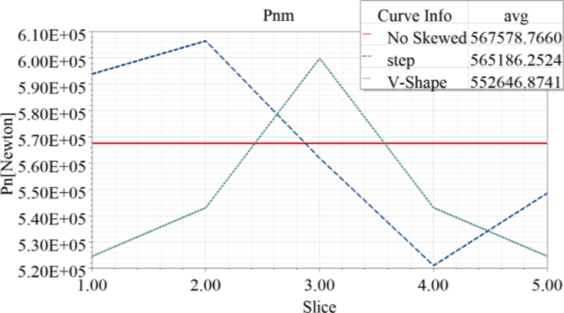
Figure 8: Distribution diagram of radial force peak under different schemes.
V. MULTI-OBJECTIVE HIERARCHICAL OPTIMIZATION OF IPMSM STRUCTURE PARAMETERS
The optimization principle of this paper is as follows: on the premise of not changing the external structure of the motor and not affecting other performance of the motor, the structural parameters of the motor are optimized based on V-shaped skewed slots optimization to reduce the radial electromagnetic force and electromagnetic torque ripple of the motor, so as to suppress the electromagnetic noise.
A. Determination of optimization objectives
The basis of optimization objectives selection is:
(i) The peak value of radial electromagnetic force and tangential electromagnetic torque ripple are related to the magnitude of vibration and noise directly, and the suppression of these two targets can produce better results;
(ii) Since the direct suppression process of vibration noise is coupled to multiple physical fields, there is a high demand for computer processors and hard disks, so the indirect suppression process of independent magnetic field calculation with higher efficiency under the same computing power is adopted.
Therefore, the indirect suppression of electromagnetic noise method has been adopted in this paper, and tangential electromagnetic torque has been taken into account to suppress electromagnetic noise. The optimization objective has been determined as follows.
(i) The peak value of radial electromagnetic stress distribution along the circumference of the air gap is the smallest, that is:
| (20) |
(ii) The torque ripple is minimal, that is:
| (21) |
is indicated as:
| (22) |
where , and are the maximum, the minimum and the average of the output torque, respectively.
(iii) The average of tangential electromagnetic torque is maximal, that is:
| (23) |
is denoted by:
| (24) |
where is the time of one cycle of the output torque waveform of the motor. is the output electromagnetic torque of the motor.
B. Determination of optimization variables
The magnitude of the radial excitation force harmonics (especially tooth-harmonics) is closely related to the size and shape of the pole arc, the length of the air gap and the size of the magnetic permeability wave caused by the slot of the stator and rotor. Therefore, these effective methods, i.e., optimizing the size and shape of the pole arc of IPMSM to make the radial excitation force density waveform close to sine as much as possible and optimizing the size of the stator and rotor slots (especially the notch), so as to reduce the electromagnetic vibration noise caused by the tooth and slot, can be used to reduce the electromagnetic noise of the motor. Table 4 shows the selected optimization variables and their corresponding value ranges.
Table 4: Initial value and variation range of optimization parameters
| Optimization Parameters | Initial Value | Value Range |
|---|---|---|
| 0.5 | 0.35 0.7 | |
| 0.5 | 0.35 0.7 | |
| 23 | 20 25 | |
| 2.5 | 1.9 4.1 | |
| 5.2 | 4 6 | |
| 7.5 | 6-8.6 | |
| 1 | 0.7 1.3 | |
| 5 | 2 8 | |
| 37.6638 | 37.0136 38.1787 | |
| 4.6466 | 4.0892 5.3504 |
C. Sensitivity analysis and parameter classification
OptiSLang software is used to analyze the sensitivity of structural parameters, and screen and grade structural parameters based on the prediction coefficient. IPMSM is analyzed and optimized under the V-shaped skewed slots scheme, and Advanced Latin Hypercube Sampling (ALHS) based on Monte Carlo sampling is adopted for sampling. A total of 100 samples were collected for the sample space composed of 10 structural parameters and their variation ranges. This method can not only ensure the accuracy of sensitivity analysis but also reduce the amount of calculation, and is suitable for sensitivity analysis when the number of parameters is less than 50. Furthermore, the influence of the irrelevant relationship between parameters on the subsequent sensitivity analysis results is minimized by introducing a random evolutionary strategy, so that relatively accurate results can still be obtained in the case of smallsamples [15].
In order to calculate more efficiently, the Coefficient of Prognosis (CoP), based on polynomial fitting, is used to evaluate the sensitivity of the target. Based on the collected samples and the corresponding solution results, the polynomial regression equation fitting the objective function to the analysis parameter is:
| (25) |
where is the determinant of the polynomial coefficient, is the fitting error, and is the polynomial about the structural parameters, which can be denoted by:
| (26) |
We define the total variation of the output as:
| (27) |
where is the actual value of the sample target, is the average of the sample target, and is the number of samples.
We define the sum of squares of all prediction errors as:
| (28) |
where is the corresponding calculated value for the .
The prediction quality evaluation index is:
| (29) |
The larger the value of , the greater the influence of structural parameters on optimization objective , and the higher the sensitivity.
Table 5: Sensitivity analysis results of structural parameters
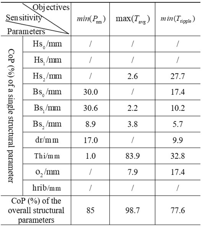
The optimization design of IPMSM can be simplified to the multi-stage and multi-physical field optimization through sensitivity analysis [19]. The sensitivity of each parameter to each optimization target and the overall sensitivity results are shown in Table 5 after the sensitivity calculation of structural parameters. The following conclusions can be drawn from Table 5:
(i) The values of CoP of overall structural parameters of the three optimization objectives are all above 75%, indicating that the determined structural parameters have high sensitivity to the three optimization objectives;
(ii) High sensitivity parameters: , , and have a high influence on one or more of the three optimization objectives. The values of CoP of them are bigger than 20%, so they are set as high sensitivity parameters.
(iii) Low sensitivity parameters: and only affect two objectives and the values of CoP are below 20%, and the sensitivity of to the three optimization objectives is all below 20%, so these three structural parameters are set as low sensitivity parameters.
(iv) Irrelevant parameters: , and don’t have corresponding CoP value, so they do not participate in the optimization in the next stage. The number of structural parameters to be optimized is reduced to 7.
D. Process of hierarchical optimization
The appropriate optimization method is adopted for each level of parameters to reduce the calculation amount and to improve the accuracy of optimization for each parameter based on the results of sensitivity classification [20]. The process of hierarchical optimization of structural parameters is shown in Fig. 9.
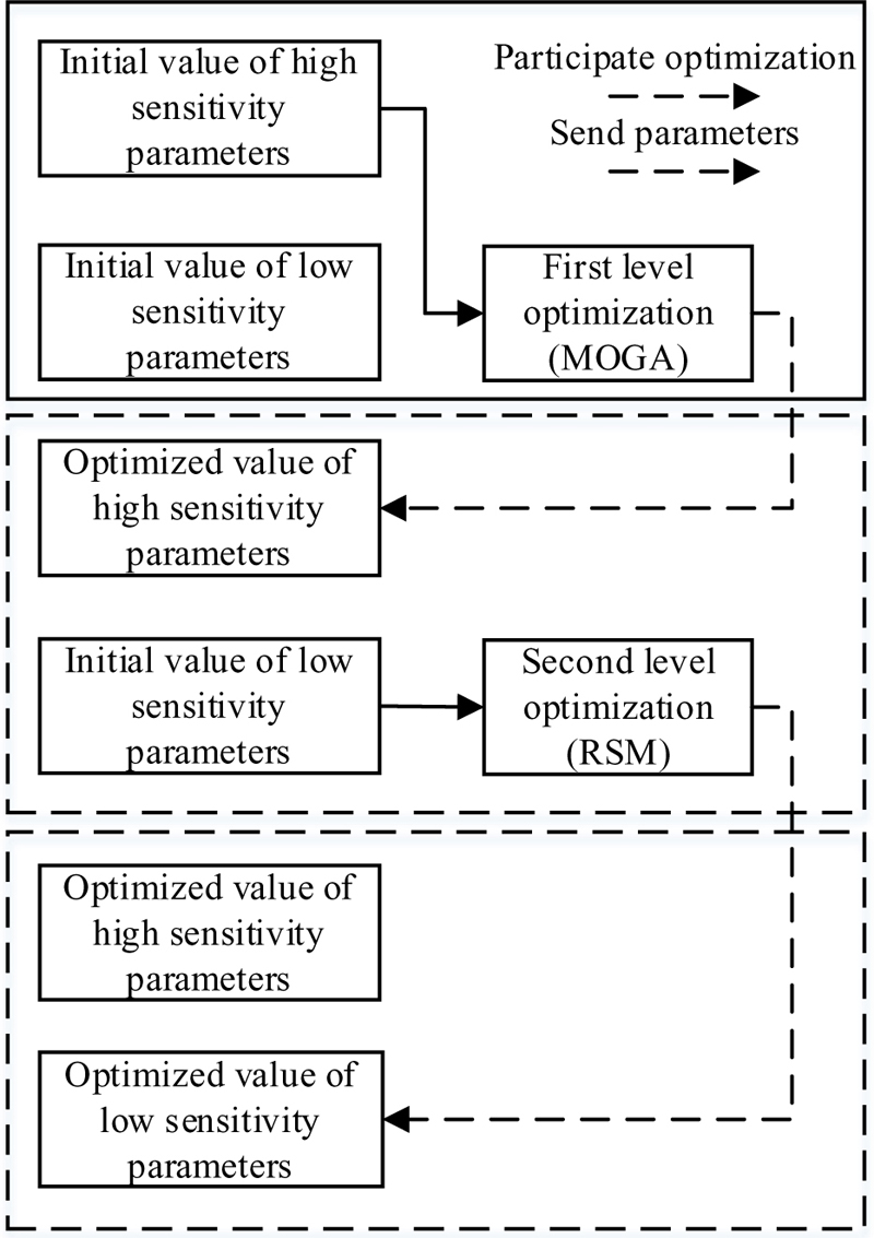
Figure 9: Optimization flow of structure parameter hierarchical optimization.
ALHS is used to sample in the optimization space and determine the initial samples of all levels of optimization, and an adaptive strategy is introduced to determine the samples of each iteration, so as to improve the randomness and global character of the initial samples and iterations and reduce their global influence on the optimization results [15].
After a round of hierarchical optimization being completed, the global nature of the optimization results under a given optimization environment is judged, and the optimized structural parameters are imported into the optimization process as initial values for the second round of optimization. If the difference between the value of the multi-objective optimization function after the second round optimization and the result of the first round is less than 2%, the first round result is judged to meet the global requirements, and the first round result is output as the final optimization result of the structural parameters. Otherwise, the next round of optimization is carried out based on the results of the second round of hierarchical optimization until the global demand is met. The overall judgment process of hierarchical optimization results is shown in Fig. 10.
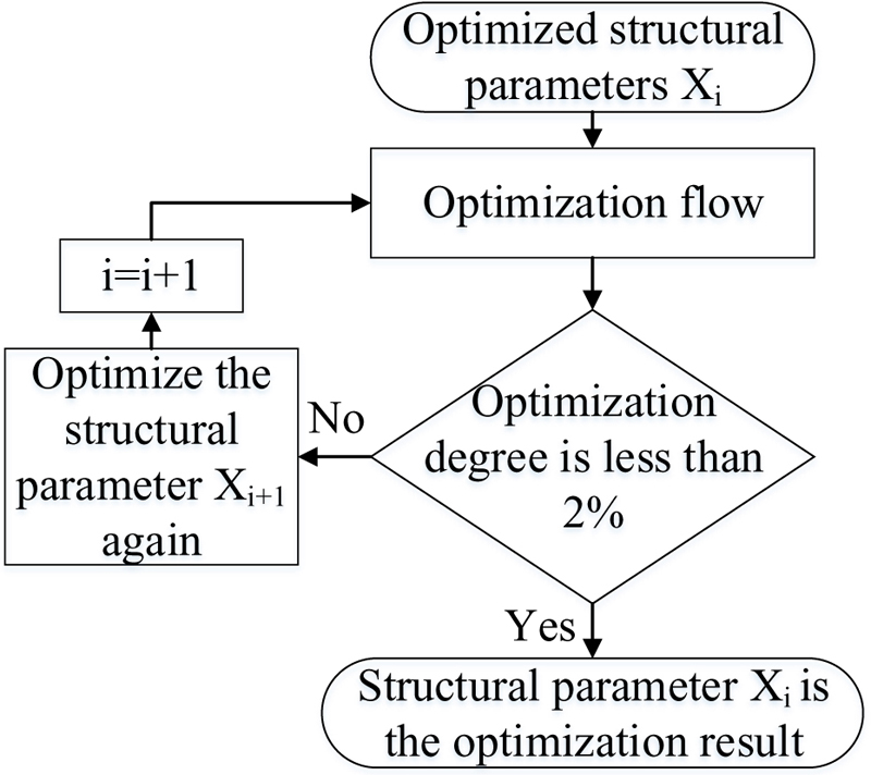
Figure 10: Global judgment process of optimization.
The optimal solution of Pareto solution set obtained by all levels of optimization in the optimization process can be selected by normalized weighting function, and the weighting function can be expressed as:
| (30) |
where , and are the maximum value of the optimized tangential electromagnetic torque mean value, the optimized radial electromagnetic force peak value and the minimum value of torque ripple, respectively. is the solution in the Pareto solution set. , and are result of each optimization scheme. , and are the weight coefficients of three optimization objectives [21]. Because the main purpose of this optimization is to suppress electromagnetic noise, the radial electromagnetic force density and torque ripple weight coefficient are higher, and the values of , and are set to 0.2, 0.4 and 0.4, respectively.
E. First round optimization of highly sensitive parameters
The highly sensitive parameter optimization includes four structural parameters and three optimization objectives, which belongs to multi-parameter and multi-objective optimization, and it is difficult to construct a direct functional relationship between structural parameters and optimization objectives. The four structural parameters have a great influence on the optimization objectives, which requires deep optimization and a large amount of calculation. The three optimization objectives of , and are contradictory and need to be considered in a compromise. Multi-objective genetic algorithm (MOGA) is used for global optimization. For multi-objective optimization and tradeoff among optimization objectives, the optimal solution set is given by using Pareto frontier.
The sample size is set to 200, the initial population is 20, the crossover probability is 50%, and the mutation probability is 14%. The generated Pareto frontier is shown in Fig. 11. The first round of optimization results obtained after selecting Pareto solution sets of high sensitivity parameters by using the normalized weighting function is shown in Table 6.
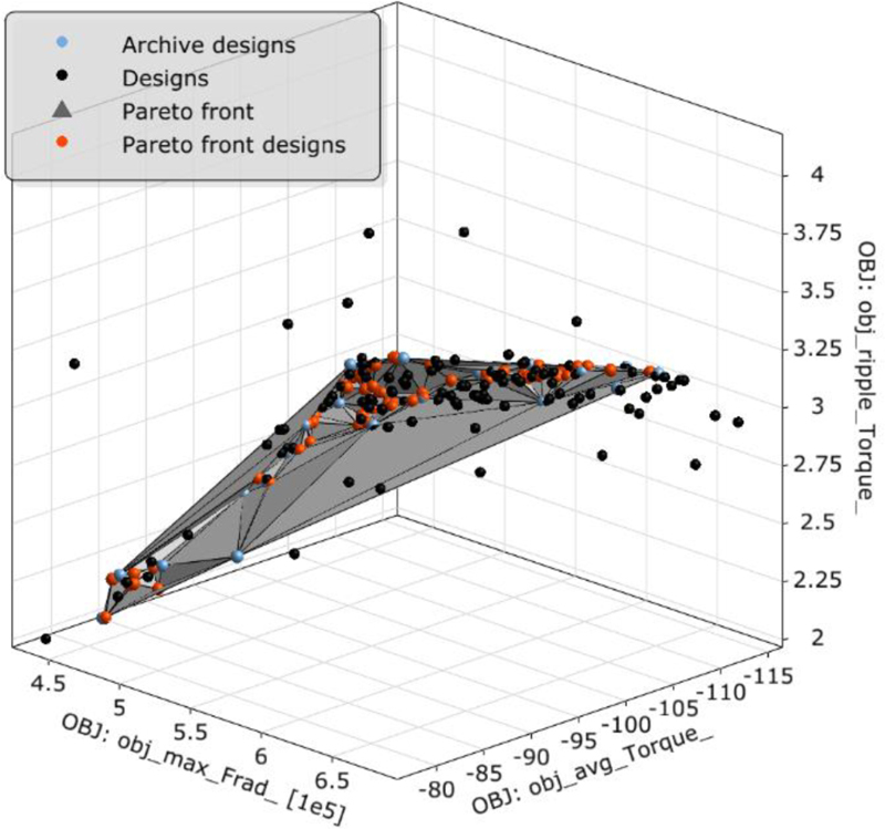
Figure 11: Pareto front surface of multi-objective optimization.
Table 6: Results of high sensitivity optimization
| Parameters/Objectives | Pre-optimization Value | Post-optimization Value |
|---|---|---|
| 2.5 | 2.012727 | |
| 5.2 | 5.851049 | |
| 23 | 21.34658 | |
| 5 | 5.49087 | |
| 552646.9 | 433154.7 | |
| 2.8476 | 2.424988 | |
| 103.83 | 104.3193 |
It can be seen from Table 6 that each optimization index of high sensitivity parameters has improved to some extent after optimization by . The peak of radial electromagnetic force density has decreased by 27.59%, the mean of tangential electromagnetic torque has increased by 0.47%, and the torque ripple has decreased by 17.43%. The values of the four highly sensitive parameters are modified to the optimized values after the optimization is completed, which are used as fixed values to participate in the subsequent optimization.
F. First round of optimization of low sensitivity parameters
The low sensitivity parameter optimization includes three structural parameters and three optimization objectives, which belongs to multi-parameter multi-objective optimization. The influence of the three parameters on the optimization objectives is smaller than that of the highly sensitive parameters, so it is unnecessary to collect many samples. Therefore, the response surface method is used to optimize the low sensitivity parameters. The low sensitivity optimization results can also be evaluated based on the multi-objective normalized optimization function in the optimization process. Table 7 shows the changes of parameters and target values after optimization of low sensitivity parameters.
It can be seen that after the low sensitivity parameters optimization, the peak of radial electromagnetic density has been reduced by 13.45%, the torque ripple has been reduced by 7.37%, but the mean of tangential electromagnetic torque has been reduced by 8.1%. The comprehensive optimization index has been improved to some extent.
Table 7: Results of low sensitivity optimization
| Parameters/Objectives | First Level Optimization Value | Second Level Optimization Value |
|---|---|---|
| 37.6638 | 37.016 | |
| 7.5 | 8.4408 | |
| 1 | 1.2984 | |
| 433154.7 | 374870 | |
| 2.424988 | 2.6218 | |
| 104.3193 | 96.634 |
G. Global judgement of hierarchical optimization results
The optimized results of Tables 6 and 7 are imported into the hierarchical optimization process again as the results of the first round of optimization, and the second round of hierarchical optimization is carried out. The comparison of the two rounds of optimization results is shown in Table 8. The multi-objective optimization function is reduced by 0.29%, and the improvement degree is less than 2% after the second round of optimization. According to the global judgment process, the final output is the optimization result of the first round. This shows that the results obtained by hierarchical optimization of the seven structural parameters have better global performance in the optimization space composed of the given initial optimization value and optimization range [15].
Table 8: Comparison of two rounds of hierarchical optimization results
| Parameters/Objectives | First Round Results | Second Round Results |
|---|---|---|
| 2.012727 | 2.169249 | |
| 5.851049 | 5.838322 | |
| 8.4408 | 8.5995 | |
| 21.34658 | 21.94714 | |
| 5.49087 | 5.596182 | |
| 1.2984 | 1.2988 | |
| 37.016 | 37.67575 | |
| 374870 | 373730 | |
| 2.6218 | 2.6313 | |
| 96.634 | 96.411 |
VI. VERIFICATION OF OPTIMIZATION EFFECT OF IPMSM
A. Finite element verification of hierarchical optimization results
Figure 12 shows the comparison of the distribution of electromagnetic excited force before and after the optimization of structural parameters. It can be seen that the peak value of radial force is 373534.2742N after the optimization of structural parameters, which decreases by 34.19% compared with that without skewed slots and 28.79% compared with the V-shaped skewed slots.
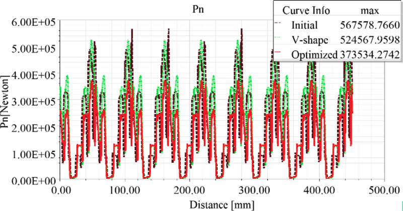
Figure 12: Comparison of radial force distribution before and after optimization of structural parameters.
Many radial electromagnetic force harmonics of different orders and frequencies will be generated in the air gap of PMSM when the electromagnetic fields of the stator and rotor interact, which are the main factors leading to radial vibration of the stator core of the motor. The harmonic optimization of the radial electromagnetic force wave is shown in Fig. 13. list the spatial distance X and amplitude Y of force waves with different orders, and the relationship between force wave order and spatial distance X is expressed as:
| (31) |
where is the radius of the air gap circumference.
The major orders of space harmonics of radial electromagnetic waves converted by (31) are shown in Table 9. The 8th order force wave is the radial force wave with frequency , which is mainly generated by the magnetic field of the main wave. The 0th and 8th order force waves are also lower order force waves modulated by the first order tooth-harmonic magnetic field of the stator and the harmonic magnetic field of the rotor. The 48th, 96th and 144th order force waves are the radial force waves generated by the interaction between the stator and the rotor harmonic magnetic field, and also the radial force waves generated by the interaction between the stator tooth-harmonic magnetic field and the permanent magnet rotor magnetic field.
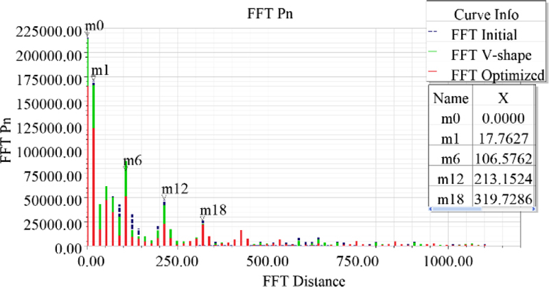
Figure 13: Harmonic optimization of radial electromagnetic waves.
Table 9: Optimization of the main spatial harmonic order of radial electromagnetic waves
| Point | Initial Force /N |
V-shape Force /N |
Optimized Force /N |
||
| m0 | 0.0000 | 0 | 216912.80 | 214192.01 | 165369.22 |
| m1 | 17.7627 | 8 | 170873.21 | 166385.01 | 121907.56 |
| m6 | 106.5762 | 48 | 77168.65 | 87619.53 | 51467.84 |
| m12 | 213.1524 | 96 | 47800.92 | 42057.04 | 23221.42 |
| m18 | 319.7286 | 144 | 25985.30 | 22815.83 | 21879.61 |
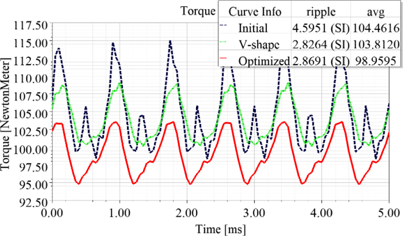
Figure 14: Ripple torque before and after optimization.
From Fig. 13 and Table 9, it can be seen that the fundamental, the 8th, 48th, and 96th order harmonics after the optimization of structural parameters are further reduced on the basis of the V-shaped skewed slots optimization, indicating that the electromagnetic vibration noise is effectively suppressed.
The comparison between torque ripple and average torque before and after optimization of structural parameters is shown in Fig. 14. After the compromise of multiple optimization objectives, the torque ripple after optimization is 2.8691, which is 41.44% lower than that before optimization and basically equivalent to the effect of V-shape skewed slots optimization. The average torque after optimization is significantly lower than the initial value and the V-shaped skewed slots, but the average torque in the V-shaped skewed slots is basically the same as the initial value.
B. Modal optimization analysis of IPMSM stator structure
Motor vibration not only depends on the stress of exciting vibration of motor, but also relates to the natural vibration characteristics of the motor structure, including the natural vibration mode and natural frequency of the motor structure itself. The motor stator is a circular structure, and the radial electromagnetic force directly acts on the teeth and magnetic poles of the stator. The natural vibration modes of this stator ring model are mainly the radial modes of different orders, and the order of the vibration mode of corresponding shape of the stator is usually defined by the order of the force wave, that is, [22].
The resonance effect will occur, making the motor produce larger vibration and noise, when the frequency and order of the radial electromagnetic excited force wave are close to or consistent with the corresponding natural frequency and natural vibration mode order of the motor stator.
The specific relationship between the natural frequency of each vibration mode and the motor structure can be summarized as follows:
(i) The natural frequency is closely related to the average radius of the stator yoke. The natural frequency is approximately inversely proportional to for breathing mode . The natural frequency is approximately inversely proportional to the square of and, the larger the radius, the lower the natural frequency for the other mode .
(ii) The natural frequency is also closely related to the order of the mode and is approximately proportional to the square of .
(iii) The natural frequency is also related to the yoke thickness , mainly the ratio of the thickness of the stator yoke to its average radius, i.e., . A large indicates that the stiffness of stator is large, and the natural frequency will be high. Small indicates that the stiffness of stator is small, and the natural frequency will be low.
The inherent modes of a certain order can be understood and the actual modes of each order can be predicted through modal analysis of IPMSM [7]. The natural vibration modes of the stator model corresponding to the 1st to 4th order are shown in Fig. 15.

Figure 15: Stator natural vibration modes of each order: (a) , (b) , (c) , and (d) .
Table 10: Comparison of motor natural frequency before and after optimization
| Orders Frequency/Hz Optimization |
r = 1 | r = 2 | r = 3 | r = 4 |
|---|---|---|---|---|
| Initial | 397.78 | 676.12 | 978.05 | 1503.9 |
| V-shaped | 404.29 | 706.49 | 992.45 | 1557.5 |
| Optimized | 403.64 | 705.9 | 992.09 | 1558.4 |
The comparison of natural frequencies of each order for stator skew slots optimization and structural parameter optimization is shown in Table 10. After the stator skew slots is used, the natural frequency is improved, and the natural frequency is slightly reduced after the structural parameter optimization, which proves that the optimization of motor body structure parameters can improve the natural frequency of motor stator structure and effectively reduce the resonance risk.
C. Optimization verification of vibration and noise suppression of IPMSM
The stator will produce a continuous steady state harmonic response when the periodic electromagnetic excitation force is applied to the stator of the motor, and the dynamic balance equation of the stator is expressed as:
| (32) |
where , , and are the mass, mechanical damping coefficient, and stiffness of the stator vibration system, respectively, is simple harmonic exciting force, and . is the vibration acceleration of the stator vibration system, is vibration speed and is vibration displacement.
Let the solution of (32) be:
| (33) |
Substitute (33) into (32) to get:
| (34) |
According to equation (34), when , the system will resonate, and the square of the resonant frequency is:
| (35) |
When the excitation frequency is far away from the resonance frequency, the damping coefficient is much less than , which is ignored, and (35) substituted into (34) obtains:
| (36) |
For the r-order vibration mode , the equivalent distributed stiffness of the stator core is approximately proportional to , that is:
| (37) |
Substitute (37) into (36) and take into account to get:
| (38) |
According to (38), the response of motor vibration system under simple harmonic excitation is still harmonic. The vibration amplitude is directly proportional to the excitation force . The response frequency is equal to the excitation force frequency. The system will resonate and produce a large amplitude when the exciting frequency of the exciting force is close to the natural frequency of the motor vibration system. In addition, is approximately inversely proportional to , so the smaller order r should be focused on.
(1) Vibration and noise evaluation criteria
Since the vibration frequency of the motor is mostly in the mid-frequency band (f=101000 Hz), the harm of mid-frequency vibration is mainly reflected in the transmission scale of vibration energy, such as the noise generated by vibration and fatigue damage of vibration components, and the vibration energy is proportional to the square of the vibration speed, so the vibration speed is used as the characteristic quantity in the vibration test.
The motor is regarded as a spherical radiator, and the radiation sound intensity is:
| (39) |
where is the relative radiated sound intensity of the spherical radiator, which can be obtained by the curve shown in Fig. 16, sound velocity is an inherent parameter of the medium, which depends on the density and elastic modulus of the medium, and can be expressed as:
| (40) |
The sound power radiated by the motor housing is:
| (41) |
where is the radius of the housing and is the length of the housing.
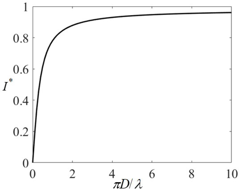
Figure 16: Relative radiated sound intensity of a spherical radiator.
According to (41), the equivalent radiated power of the motor is proportional to the square of the amplitude of vibration velocity of the motor stator housing. The amplitude of the vibration density can be expressed as the product of the vibration displacement amplitude and vibration frequency. ERPL is used to characterize the harmonic response of the motor [23], and the expression is:
| (42) |
where is the reference equivalent radiated power, generally taken as .
(2) Vibration and noise suppression optimization results
The air-gap electromagnetic stress of the stator housing after the structural parameter optimization is shown in Fig. 17. The red part is the imported electromagnetic excitation force, including radial electromagnetic force and tangential torque.
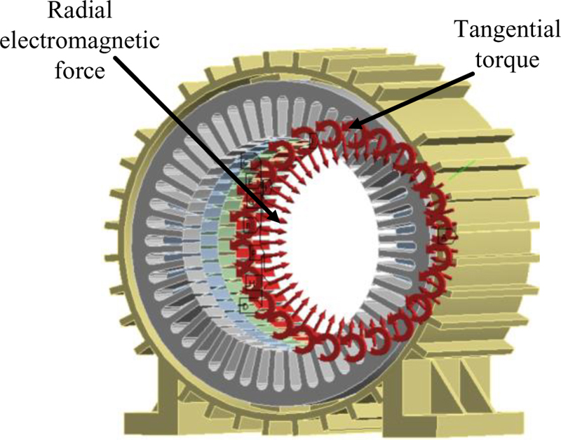
Figure 17: Radial electromagnetic force and torsional force model after optimization of structural parameters.
The chassis base is set as a fixed constraint, and the frequency band is considered as 601 segments. The modal superposition method is used to solve the multi-speed EPRL waterfall diagram of IPMSM, and the speed range is from 1000 rpm to 6000 rpm. The ERPL waterfall diagram of IPMSM is obtained in Fig. 18 after harmonic response analysis.
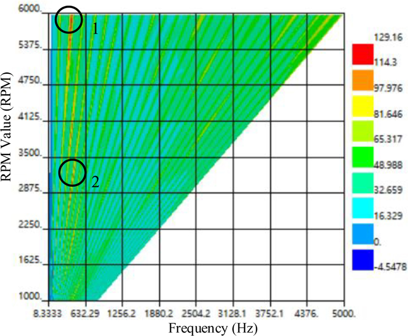
Figure 18: ERPL waterfall diagram of the initial motor model.
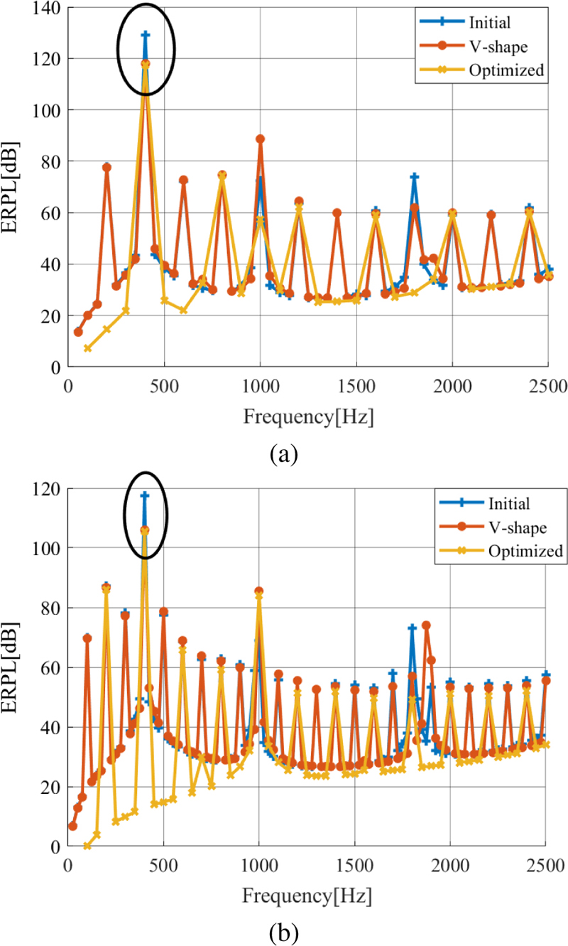
Figure 19: Line diagram comparison of ERPL before and after optimization: (a) line diagram comparison of ERPL on 6000 rpm and (b) line diagram comparison of ERPL on 3000 rpm
As can be seen from Fig. 18 corresponding to 6000 rpm, that is, at mark point 1, the color is the darkest and the ERPL value is the largest, reaching 129.16 dB. According to the electromagnetic force theory, this is because the vibration frequency of the motor housing is close to the natural frequency, it causes a large vibration noise. Another darker point corresponding to 3000 rpm, namely, mark point 2, has an ERPL value of 117.4 dB, which is generated by the interaction of the stator magnetomotive force harmonics themselves, and the vibration frequency is twice the fundamental frequency.
Figure 19 shows the ERPL line chart comparison of the motor before and after optimization. It can be seen from Fig. 19 (a) that the maximum value of ERPL is at the vibration frequency of 400 Hz at 6000 rpm, which is equal to the natural frequency at the vibration order. Moreover, the ERPL value is reduced from 129.16 dB to 117.98 dB to 117.25 dB from initial model to V-shaped skewed slots to structural parameter optimization. Compared with that of initial model, the optimized ERPL is reduced by 8.65% and 9.22%, respectively, indicating that the natural frequency of the stator housing of the motor can be changed through structural optimization and structural parameter optimization, so that the vibration and noise suppression caused by resonance is better. Figure 19 (b) shows that the maximum value of ERPL corresponding to 3000 rpm is also at the vibration frequency of 400 Hz, and the ERPL value decreases from 117.40 dB to 106.03 dB and then to 105.52 dB from initial model to V-shaped skewed slots and then to structural parameter optimization. After optimization, the ERPL is reduced by 9.68% and 10.12%, respectively, which proves that the harmonic components in the vibration response of the motor can be effectively reduced by optimization, so as to obtain better vibration noise suppression effect.
VII. CONCLUSION
The vibration and noise of 48-slot 8-pole IPMSM suitable for new energy vehicles are suppressed by combining structural optimization and structural parameter optimization, and the following conclusions are drawn:
(1) The radial force wave causing electromagnetic vibration noise is a spatiotemporal harmonic function, the main orders of the space harmonics are an integer multiple of the order 8 of main wave magnetic field, and the frequency of the time harmonics are an integer multiple of the power supply frequency twice.
(2) Compared with the step skewed slots optimization, the V-shape stator skewed slots structure is a better scheme for skewed slots structure optimization, and the radial force is reduced by 2.62%.
(3) The sensitivity of the motor structure parameters to the optimization objective has been calculated by the evaluation index of CoP, and the structure parameters have been classified into high sensitive parameters, including , , and , and low sensitive parameters, covering , , and , and irrelevant parameters, involving , and .
(4) MOGA and RSM have been integrated to optimize the structural parameters of the motor hierarchically, and global verification has been carried out.Considering the compromise of the three optimization objectives, the torque ripple increases slightly on the basis of the V-shaped skewed slots optimization, but decreases 41.44% compared with the initial value. The continuous reduction of the average torque results in the reduction of the peak value of the radial electromagnetic force by 28.79% on the basis of V-shaped skewed slots optimization, and significant reduction of the peak value of the major orders spatial harmonics of the electromagnetic force, which is in line with the expected optimization goal.
(5) The results of vibration and noise suppression optimization show that the optimization method proposed has obvious suppression effect on the larger amplitude of the vibration noise caused by resonance and the main order vibration and noise harmonics, and the ERPL values in the two cases are reduced by 9.22% and 10.12%, respectively, which is better than the vibration and noise suppression effect of V-shaped skewed slots optimization.
ACKNOWLEDGMENT
The authors would like to thank the National Natural Science Foundation of China (Grant no. 62173165) and the Modern Education Technology Research Project of Jiangsu Province (Grant no. 2021-R-91852), Jiangsu Normal University Graduate Research and Practice Innovation Project (2022XKT0162) for providing funds and equipment for this research.
REFERENCES
[1] R. Fu, “Design and parameter research of permanent magnet synchronous motor for electric bus,” Ph.D. thesis, Northwestern Polytechnical University, 2015.
[2] K. Luo, S. L. Wu, C. Ren, and Y. Liu, “Analysis and control of electromagnetic noise of permanent magnet synchronous motor for electric vehicle,” Electric Drive, vol. 52, no. 10, pp. 15-20, 2022.
[3] Z. Qian, T. X. Liu, W. Z. Deng, and Q. J. Wang, “Vibration and noise suppression of vehicle permanent magnet synchronous drive motor with current harmonic injection,” Electric Machines and Control, vol. 26, no. 07, pp. 115-124, 2022.
[4] D. Wang, C. Peng, J. Li, and C. Wang, “Comparison and experimental verification of different approaches to suppress torque ripple and vibrations of interior permanent magnet synchronous motor for EV,” IEEE Transactions on Industrial Electronics, vol. 70, no. 3, pp. 2209-2220, 2023.
[5] X. Li, W. He, and R. Zhao, “Modal analysis of the stator system of a permanent magnet synchronous motor with integer slot multi-pole pair for electric vehicles,” IET Electric Power Applications, vol. 16, no. 1, pp. 1-14, 2022.
[6] X. Y. Wang, X. Y. Luo, and P. Gao, “Rotor structure design based on optimization of vibration and noise of electric vehicle drive motor,” Proceedings of the CSU-EPSA, vol. 35, no. 1, pp. 44-50, 77,2023.
[7] Y. Xie, W. Xin, W. Cai, and Y. J. Fan, “Electromagnetic performance and electromagnetic vibration noise analysis of different rotor topologies of interior permanent magnet synchronous motor,” Electric Machines and Control, vol. 27, no. 1, pp. 110-119, 2023.
[8] Z. X. Li, J. K. Xia, T. Liu, and Z. Y. Guo, “Reduction of sixfold frequency vibration and noise of surface mounted permanent magnet motors based on virtual tooth structure between poles,” Transactions of China Electrotechnical Society, vol. 38, no. 5, pp. 1287-1298, 2023.
[9] Y. Li, S. P. Li, J. W. Zhou, and L. N. Li, “Vibration and noise reduction method of near-pole slot permanent magnet synchronous motor based on stator tooth cutting,” Transactions of China Electrotechnical Society, vol. 30, no. 6, pp. 45-52, 2015.
[10] Q. J. Wang, Y. D. Zheng, and X. Z. Liu, “Research on suppression of motor vibration and noise based on structural parameter optimization,” Journal of Electrical Engineering, pp. 1-10, 2023.
[11] T. Bdour and A. Reineix, “Global sensitivity analysis and uncertainty quantification of radiated susceptibility in PCB using nonintrusive polynomial chaos expansions,” IEEE Transactions on Electromagnetic Compatibility, vol. 58, no. 3, pp. 939-942, 2016.
[12] D. Torregrossa, F. Peyraut, M. Cirrincione, C. Espanet, A. Cassat, and A. Miraoui, “A new passive methodology for reducing the noise in electrical machines: Impact of some parameters on the modal analysis,” IEEE Transactions on Industry Applications, vol. 46, no. 5, pp. 1899-1907, 2010.
[13] J. C. Shi, C. Qian, and Y. Yu, “Evolutionary multi-objective optimization made faster by sequential decomposition,” 2017 IEEE Congress on Evolutionary Computation (CEC), Donostia, Spain, pp. 2488-2493, 2017.
[14] S. G. Zuo, C. G. Ma, and R. He, “Analysis and optimization of radial force wave sensitivity of permanent magnet synchronous motor for vehicles,” Vibration, Testing and Diagnosis, vol. 33, no. 3, pp. 357-363, 2013.
[15] Y. T. Luo and R. H. Lu, “Electromagnetic noise suppression of motor based on hierarchical optimization of structural parameters,” Transactions of China Electrotechnical Society, vol. 36, no. 14, pp. 2957-2970, 2021.
[16] W. Deng and S. Zuo, “Electromagnetic vibration and noise of the permanent-magnet synchronous motors for electric vehicles: An overview,” IEEE Transactions on Transportation Electrification, vol. 5, no. 1, pp. 59-70, Mar. 2019.
[17] J. Du, Y. Li, Z. Yu, and Z Wang, “Research on radial electromagnetic force and vibration response characteristics of squirrel-cage induction motor fed by PWM inverter,” IEEE Transactions on Applied Superconductivity, vol. 31, no. 8, pp. 1-4,2021.
[18] Y. X. Chen, Analysis and Control of Motor Noise, Hang Zhou: Zhejiang University Press, 1987.
[19] T. Song, H. Liu, and Q. Zhang, “Multi-physics and multi-objective optimization design of interior permanent magnet synchronous motor for electric vehicles,” IET Electric Power Applications, vol. 14, no. 11, pp. 2243-2254, 2020.
[20] X. Zhu, J. Huang, L. Quan, Z. Xiang, and B. Shi, “Comprehensive sensitivity analysis and multiobjective optimization research of permanent magnet flux-intensifying motors,” IEEE Transactions on Industrial Electronics, vol. 66, no. 4, pp. 2613-2627, Apr. 2019.
[21] L. Liu, Y. Huang, M. Zhao, and Y. Ruan, “Parametric Modeling and Optimization of Switched Reluctance Motor for EV,” Applied Computational Electromagnetics Society (ACES) Journal, vol. 37, no. 9, pp. 948-958, Sep. 2022.
[22] S. G. Zuo, Noise and Vibration of Vehicle Synchronous Motor, Bei Jing: Mechanical Industry Press, 2021.
[23] T. F. Song, “Research on electromagnetic vibration and noise suppression of permanent magnet synchronous motor for electric vehicle,” Ph.D. thesis, Beijing Jiaotong University, 2022.
BIOGRAPHIES

Mingwei Zhao was born in Shandong China, in 1975. He received the M.S. degree in power electronics and power drive from Nanjing University of Aeronautics and Astronautics, Nanjing, China, in 2012, and is currently pursuing the Ph.D. degree in control science and control engineering from Shanghai University, Shanghai, China.
Since 2006, he has been an experiment lecturer with the school of Electrical Engineering and Automation, Jiangsu Normal University, Xuzhou, China. He is the author of 10 articles. His research interests include the robot dynamic drive and cooperative control and industrial motion control system.

Xiangyu Wang was born in Jiangsu, China. He received the B.S. degree in electrical engineering from Jinling Institute of Science and Technology, Nanjing, China, in 2019, and is currently pursuing the M.S. degree in Electrical Engineering from Jiangsu Normal University, Xuzhou, China. His research interests include design and optimization of new energy electric drive system.

Lijun Liu was born in Shanxi, China, in 1977. She received the M.S. degree in power electronics and power drive from China University of Mining and Technology, Xuzhou, China, in 2006.
She is currently a lecturer with the school of Electrical Engineering and Automation, Jiangsu Normal University, Xuzhou, China. She has published more than 10 articles. Her research interests include design and optimization of new energy electric drive system and industrial motion controlsystem.

Xiaowei Tu received the Ph.D. degree from University of Technology of Compiegne (UTC), France in 1987. He worked as professor in UTC, and later he became a researcher in French National Research Center (CNRS) in early 1990s. Since 1997, he has been working also as a researcher and R&D project manager in different Canadian research institutes.
He is currently a professor at the School of Mechatronic Engineering and Automation, Shanghai University, China.

Qinghua Yang was born in Shandong, China, in 1981. Ph.D., Associate professor, master supervisor. His research interests include sensor design and development, aviation ground detection and integrated Testing, industrial measurement and control system development and embedded control.
ACES JOURNAL, Vol. 39, No. 1, 64–80
doi: 10.13052/2024.ACES.J.390109
© 2024 River Publishers