Study on Partial Coating Approach for Reducing Cavity Backscattering
Cong-Bo Zhang, Xiao-Wei Huang, and Xin-Qing Sheng
Institute of Radio Frequency Technology and Software
School of Integrated Circuits and Electronics, Beijing Institute of Technology, Beijing 100081, China
3120185390@bit.edu.cn, xwhuang@bit.edu.cn, xsheng@bit.edu.cn
Submitted On: October 1, 2023; Accepted On: September 16, 2024
ABSTRACT
Cavities are strong scattering parts for aircrafts, while coating the interior surface of cavities is a general approach for reducing cavity backscattering. In this paper, the discontinuous Galerkin (DG) method based on the self-dual integral equation (SDIE) is employed to efficiently simulate scattering from partially coated cavities. The distance sparse preconditioner (DSP) is applied to DG-SDIE for speeding up convergence instead of the conventional block-diagonal preconditioner (BDP). An efficient partial coating scheme is presented. The numerical results of straight cavity, S-shaped cavity and complex aircraft cavity demonstrate our coating scheme can achieve similar effect of reducing backscattering by using smaller coated interior surface regions. Useful conclusions about partially coating the cavity are summarized.
Index Terms: Coated cavity, discontinuous Galerkin (DG) method, distance sparse preconditioner (DSP), self-dual integral equation (SDIE).
I. INTRODUCTION
Scattering from cavity structures often contributes significantly to the overall electromagnetic (EM) scattering from aircraft. A major way to reduce EM scattering from these cavities is to coat their interior surface with EM absorbing materials. How to efficiently coat the cavity becomes an attractive problem.
Method of moments (MoM) is a powerful tool for the EM scattering problem [1–3]. The thin coating surface is usually approximated by the impedance boundary condition (IBC) [4]. Formulations of MoM based on the surface integral equation and IBC were developed in [5–8]. However, these early formulations suffered from drawbacks of an ill-conditioned matrix. A robust and efficient self-dual integral equation (SDIE) was developed for scattering from coated objects [9]. A more efficient formulation was recently developed by employing the combined field integral equation (CFIE) and IBC, shortened to C-SDIE [10]. The discontinuous Galerkin (DG) method was recently applied to C-SDIE (DG-C-SDIE) to further improve efficiency and flexibility for simulating scattering from non-uniform or partially coated cavities [11–14].
In this paper, DG-C-SDIE is employed to study scattering from partially coated cavities. A more efficient distance sparse preconditioner (DSP) is applied to DG-C-SDIE to replace the conventional block-diagonal preconditioner (BDP) used in [10]. Furthermore, a partial coating scheme is presented for more efficient coating. The numerical results of scattering from coated rectangular cavity, S-shaped curved cavity and realistic aircraft cavity demonstrate that our coating scheme can achieve the similar effects of reducing backscattering with a smaller coated surface region. Some useful results for partially coating a cavity to reduce backscattering are obtained and shown in section IV.
II. FORMULATION
Consider a coated cavity immersed in free space with permittivity and permeability . The cavity is illuminated by an incident plane wave (). Electric current J and magnetic current M on the cavity surface can be formulated by the CFIE as:
| (1) |
where denotes the outward normal vector of the cavity surface ,, , and . Operator and operator and are defined as:
| (2) | ||||
| (3) |
where denotes the free-space Green’s function with wavenumber and P.V. stands for the Cauchy principal value integration.
On the other hand, IBC can give the following relation between J and M as:
| (4) |
It should be noticed that is the normalized surface impedance of the cavity. Combining equations (1) and (4) and replacing J and M with and yields the C-SDIE equation (5).
According to the DG method, J and M are expanded with the RWG basis or half RWG basis g. The electric or magnetic current continuity between nonconformal meshes is inherently guaranteed by translating the term in the integral equation involving operator into the following four terms [14]:
| (6) |
where , are the number of the edges, g denotes either RWG basis or half RWG basis, and denotes the unit normal vector of the boundary edges.
It is found that the BDP used in [10] does not work well for a partially coated cavity. We here apply a simple and efficient preconditioner DSP to DG-C-SDIE. The entries of DSP matrix are:
| (7) |
where and represent the location of the testing and bases elements and is the free space wavelength.
III. NUMERICAL RESULTS
In the following numerical experiments, the multilevel fast multipole algorithm (MLFMA) [15] is applied to reduce CPU time and memory requirement.
A. Coating scheme
To efficiently coat the cavities, we first should select a suitable normalized surface impedance of the coating. According to [4], when the EM wave is vertically incident on the coating, the surface impedance of the coating can be equivalent as:
| (8) |
where is the thickness of the coating, and are relative permittivity and relative permeability respectively, and is the wave number in free space. The impedance boundary condition typically assumes a small tangential electric field and, therefore, the equivalent impedance at vertical incidence is generally regarded as a boundary approximation. The effectiveness of the impedance boundary condition has been extensively studied [14, 16]. To make a preliminary assessment of the wave-absorbing performance of coatings with different thicknesses, the following reflection coefficient formula for a normally incident semi-infinite space is commonly used for estimation:
| (9) |
In this paper, a real EM absorbing material with relative permittivity of (18.4, -1.09j) and relative permeability of (1.6, -1.67j) is used. The relation between reflectivity and thickness of the coat is shown in Fig. 1, where is the wavelength of absorbing material. The thickness of 0.117, 0.17 and 0.21 are chosen respectively as three coating cases (I, II, III) of the absorbing capacity from weak to strong. The normalized surface impedances are equivalent as (0.2819, 0.175j), (0.4936, 0.1302j) and (0.5927, -0.0396j), respectively.
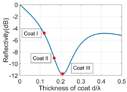
Figure 1: Relationship between reflectivity and the thickness of a coating with relative permittivity of (18.4, -1.09j) and relative permeability of (1.6, -1.67j), where is the wavelength in absorbing material.
Table 1: Comparison of numerical performance of NoP, BDP, DSP for the cavity in Fig. 2, where the degree of freedom is 5709
| Memory forPreC (MB) | CPU Time for PreC (s) | Iteration Number | IterationTime (s) | Total Time (s) | |
| NoP | —- | —- | 76 | 23.14 | 23.14 |
| BDP | 3927 | 1468.89 | 21 | 10.85 | 1479.74 |
| DSP | 277 | 6.62 | 16 | 5.79 | 12.41 |
Our coating scheme is as follows. When the frequency of the EM wave is higher than the cutoff frequency of the cavity dominant mode, the EM wave can enter the cavity. We coat the cavity interior surface area directly illuminated by the EM wave incident in all concerned angles. To further reduce the coated region, we can neglect the part which is illuminated by the EM wave incident in a small angle range and coat the part which is illuminated by the EM wave incident from a large incident angle range.
When the frequency of the EM wave is lower than the cutoff frequency of the cavity, the EM wave cannot enter the cavity. Therefore, we coat the external surface of the cavity.
B. Performance of DSP preconditioner
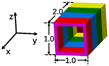
Figure 2: Rectangle cavity with coated interior surface (impedance ) and perfect electric conducting (PEC ) external surface.
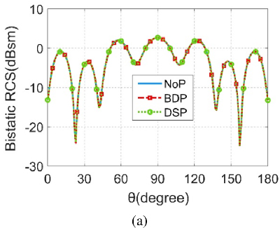
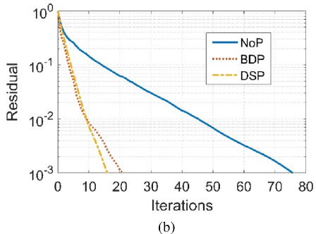
Figure 3: (a) Bistatic VV-polarized RCS and (b) iteration convergence history for the cavity in Fig. 2, applying different preconditioners.
The numerical example is a partially coated rectangular cavity whose dimension is and thickness is 0.1 m, shown in Fig. 2. The interior surface is an IBC boundary with impedance and the external surface is a perfect electric conducting (PEC) material. The cavity is illuminated by a plane wave of 300 MHz, propagating in the x-direction with the electric field polarized in the z-direction. The cavity is divided into 11 subdomains to speed up the inverse of BDP preconditioner. Each subdomain is discretized independently with mesh size . The degree of freedom (DoF) of the cavity is 5709, with 3366 DoFs for the external cavity surface and 2343 DoFs for the interior cavity surface. The numerical performance of no preconditioner (NoP), BDP and DSP are shown in Table 1. The bistatic RCS and iteration convergence history are shown in Fig. 3. From Table 1 and Fig. 3, we can observe that, compared with BDP, DSP has a little faster convergence speed but saves considerable time and memory for constructing the preconditioner matrix. Obviously, DSP is more efficient when dealing with the coated cavity problem with larger DoFs.
C. Coated straight cavity
The EM scattering properties of a partially coated straight cavity are first investigated. Let us consider a rectangular cavity with an interior surface of and a thickness of 0.1 m, as shown in Fig. 4. The surface impedance of coating is chosen as (0.2819, 0.175j). The RCS calculation angle is 6090 degrees in the -direction and 0.
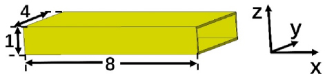
Figure 4: Parameters of the rectangular cavity (unit: meter).
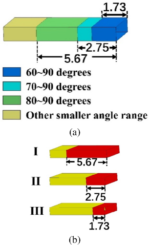
Figure 5: The four regions illuminated by the EM wave from different angular ranges in the direction and (b) the three partial coating schemes (red area is coated and the unit is meter).
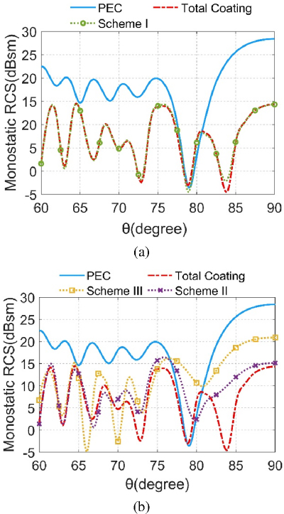
Figure 6: (a) Monostatic VV-polarization RCS of PEC cavity in which the total interior surface is coated and (b) cavity coated by three schemes in Fig. 5 (b), at a frequency of 600 MHz.
For a straight cavity, the entire cavity interior surface can be illuminated directly by the EM wave from our incident angle range. According to the surface area illuminated by EM waves in different incident angular ranges, the interior surface of the cavity can be divided into four surface regions, as shown in Fig. 5 (a). The blue region is illuminated by an incident angle range of 6090 degrees, the azure region by an incident angle range of 7090 degrees, the green area by an incident angle range of 8090 degrees and the yellow area by a much smaller incident angle range. For the straight cavity, coating the directly illuminated area is equivalent to coating the entire interior surface. According to our coating approach, three schemes are presented to further reduce the coated area, as shown in Fig. 5 (b). Scheme I coats the three regions of the blue, azure and green area; Scheme II coats the two regions of the blue and azure area; Scheme III only coats the blue region. We calculate the monostatic VV-polarization RCS of the PEC cavity, the cavity in which the total interior surface is coated (total coating), and the cavity coated by Scheme I, II and III at frequency 600 MHz.
Let us take the total coating as an example. The DoF of the cavity is 245709 with 128406 DoFs for the external cavity surface and 117303 DoFs for the interior cavity surface. The results are shown in Fig. 6. From Fig. 6, we see Scheme I has similar RCS reduction with the total coating. Scheme II also has comparable RCS reduction with the total coating, except for a little higher RCS at 8090 degrees. Scheme III has similar RCS reduction with total coating at the angle range of 6075 degrees, but less RCS reduction at the angle range of 7590 degrees, as we expected.
Next, we calculate the scattering from the above coated rectangular cavity at frequency of 15 MHz lower than the cavity dominant mode cutoff frequency of 37.5 MHz. The monostatic RCS of this coated cavity are shown in Fig. 7. As we expect, coating the interior surface of cavity cannot reduce RCS at all. For this case, coating the external surface of the cavity is the only way to reduce RCS.
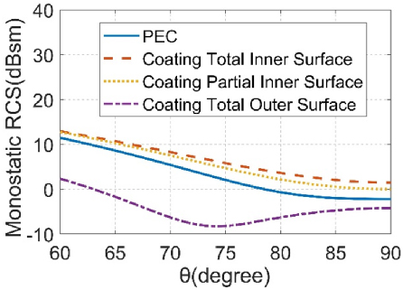
Figure 7: Monostatic VV-polarization RCS of a PEC cavity in which the total inner and partial inner surface is coated, and a cavity in which the total outer surface is coated, at frequency of 15 MHz.
D. Coated S-shaped cavity
We further investigate the EM scattering properties of the coated S-shaped cavity, which is widely used in the air inlet of stealth aircraft. As shown in Fig. 8, the model is a double S-shaped cavity with thickness 0.1 m and the specific parameters of the interior surface are as follows. The two S-shaped regions are 4.5 and 3.5 m long and offset distances in bending direction are 1.4 and 0.6 m long; The bottom is a round surface with radius of 2 m while the opening is trapezoid with a median of 3.75 m and height of 0.94 m. The surface impedance of the coat is (0.2819, 0.175j). The RCS calculation angle is 60120 degrees in the direction and 0.
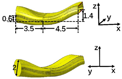
Figure 8: Parameters of double-S shaped cavity (unit: meter).
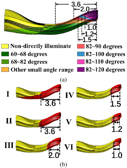
Figure 9: (a) Eight regions illuminated by an EM wave from different angular ranges in the direction and (b) six partial coating schemes (red area is coated and the unit is meter).
Based on the analysis of a coated rectangular cavity, the interior surface of the S-shaped cavity can be divided into different regions as shown in Fig. 9 (a). The yellow region is not illuminated directly by the EM wave; the dark green and light green regions are illuminated by incident angles of 6082 degrees; the red, blue, pink and purple regions are illuminated by an incident angle of 8290, 82100, 82110 and 82120 degrees; the orange region by a much smaller incident angle range. According to our coating approach, we have the following coating schemes. Scheme I only coats the region illuminated directly by the EM wave. Since the asymmetric structure of the S-shaped cavity makes the EM wave incident from large angles (82120 degrees) illuminate a small region on the upper interior surface and the EM wave incident from small angles (6082 degrees) illuminates a large region on the lower interior surface, Scheme II neglects the region on the lower surface and only coats the region corresponding to 82120 degrees. Based on Scheme II, we further neglect the orange, red, blue and pink area in turn, corresponding to Schemes III, IV, V and VI, respectively. These schemes are shown in Fig. 9 (b). The monostatic VV-polarization RCS from the PEC cavity, the total coating and the cavity coated by the above-mentioned schemes at 600 MHz are calculated. Taking the total coating as an example, the DoF of the cavity is 200893, with 104653 DoFs for the external cavity surface, and 96240 DoFs for the interior cavity surface. We here only show the monostatic VV-polarization.
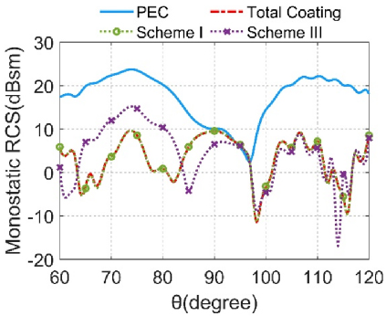
Figure 10: Monostatic VV-polarization RCS of PEC cavity in which the total interior surface is coated, and cavity coated by Scheme I and III in Fig. 9 (b), at a frequency of 600 MHz.
RCS of Scheme I and III in Fig. 10 and use the RCS from the PEC cavity and the total coating cavity as a comparison. It can be seen that Scheme I has nearly the same RCS reduction as total coating. Scheme III also has comparable RCS reduction as total coating, except for a little higher RCS at 6582 degrees, as we expected. To better demonstrate the effect of the coated area saving for reducing RCS, we defined the average reduction of RCS as:
| (10) |
where denotes the number of observation angles and 121 is used in this example, is the RCS of PEC cavity and is the RCS of the coated cavity. The relationship between the coated area ratio and the average reduction of RCS is shown as a red line in Fig. 11 and the points corresponding to Scheme IVI is marked. Clearly, coating the directly illuminated area (Scheme I) guarantees maximum (reliability for) RCS decrease and saves about 30% coating area while neglecting the area illuminated by a few angles (Scheme IIVI) saves about 5085% area respectively and maintains enough RCS reduction.
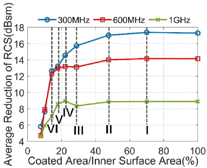
Figure 11: Relationship between average reduction of the monostatic VV-polarization RCS and coated area ratio. Frequency is altered from 300 MHz to 1 GHz.
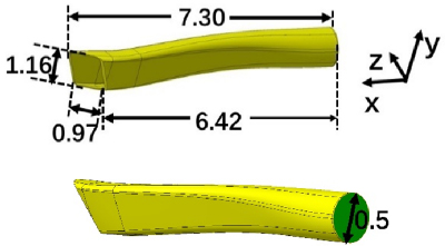
Figure 12: Parameters of a realistic air inlet (unit: meter).
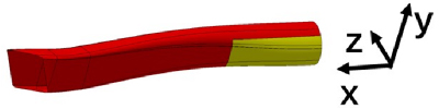
Figure 13: Partial coating scheme for cavity in Fig. 12 (red area is coated).
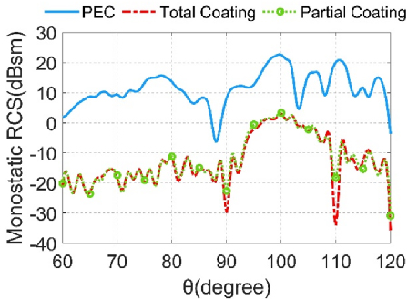
Figure 14: Monostatic VV-polarization RCS of PEC cavity in which the total interior surface is coated, and cavity partially coated by the scheme in Fig. 13, at a frequency of 4 GHz.
E. Feasibility for different frequency
In this part, the feasibility of our partial coating scheme for different frequencies is investigated. We employ the same impedance (0.2819, 0.175j), and set the different frequencies as 300 MHz, 600 MHz and 1 GHz; other parameters are the same as those in section IIID. The relationship between average reduction of the monostatic VV-polarization RCS and the coated area ratio for different coatings are shown in Fig. 11. As we see, the coated region directly illuminated (Scheme I) in the whole incident angle range has almost the same RCS reduction as the fully coated cavity for all frequencies. Moreover, we see Scheme II and III, which do not coat the interior surface illuminated by a small incident angle range, can also reduce enough RCS. All these demonstrate the applicability of our coatingscheme.
F. Complex and large cavity with partial coating
Finally, a complex and large cavity with partial coating is presented to show the performance of our partial coating scheme. We consider a real inlet of a stealth aircraft, a three S-shaped cavity, whose opening is a parallelogram of 1157*966 mm and bottom is a circle with radius of 0.5 m, as shown in Fig. 12. This cavity is 97 in length. The surface impedance of the coating is (0.4936, 0.1302j). We calculate the monostatic RCS in the incident angle range of 60120 degrees in the -direction and 0 degrees in the -direction at a frequencyof 4 GHz.
According to our partial coating scheme, a specific coating scheme is as follows. Coating the area of cavity directly illuminated in an incident angle range from 60 to 120 degrees, designated by the red area shown in Fig. 13. This coating scheme can save 11.1% coated area compared to total coating. The monostatic VV-polarization RCS of the PEC cavity, the total coating cavity and the cavity coated by our scheme are calculated. Take the total coating as an example. DoF of the cavity is 2828576 with 1464133 DoFs for the external cavity surface, and 1364443 DoFs for the interior cavity surface. RCS are shown in Fig. 14, and we can clearly see that our coating scheme can significantly reduce RCS and achieve almost the same results as the total coating.
IV. CONCLUSION
Scattering from partially coated cavities is studied efficiently and accurately by the improved DG-C-SDIE. The following useful conclusions can be obtained from the numerical experiments:
Coating the cavity interior surface region directly illuminated by the EM wave incident in whole angles can efficiently reduce backscattering and obtain almost the same RCS reduction as the total coating cavity.
The cavity interior surface illuminated by the EM wave incident in a small angle range can be further neglected and is not coated to further reduce the coated area with a little loss of RCS reduction.
For a working frequency lower than the cut-off frequency of the cavity, coating the interior cavity surface cannot reduce RCS. Instead, coating the external cavity surface is the only way to reduce the backscattering of the cavity.
ACKNOWLEDGMENT
This work was supported in part by the China National Postdoctoral Program for Innovative Talents under Grant BX20220376 and in part by the China Postdoctoral Science Foundation under Grant 2022M72041.
REFERENCES
[1] J. Hu, R. Zhao, M. Tian, H. Zhao, M. Jiang, X. Wei, and Z. P. Nie, “Domain decomposition method based on integral equation for solution of scattering from very thin, conducting cavity,” IEEE Trans. Antennas Propagat., vol. 62, no. 10, pp. 5344-5348, Oct. 2014.
[2] Z. Peng, K.-H. Lim, and J.-F. Lee, “A boundary integral equation domain decomposition method for electromagnetic scattering from large and deep cavities,” J. Comput. Phys., vol. 280, pp. 626-642, Jan. 2015.
[3] C.-B. Zhang and X.-Q. Sheng, “An efficient discontinuous Galerkin method for cavity design,” IEEE Antennas Wireless Propagat. Lett., vol. 20, no. 2, pp. 199-203, Feb. 2021.
[4] T. B. A. Senior, “Approximate boundary conditions,” IEEE Trans. Antennas Propagat., vol. 29, no. 5, pp. 826-829, Sep. 1981.
[5] K. M. Mitzner, “An integral equation approach to scattering from a body of finite conductivity,” Radio Sci., vol. 2, no. 12, pp. 1459-1470, Dec. 1967.
[6] J. Rogers, “Moment-method scattering solutions to impedance boundary condition integral equations,” Proc. Antennas Propagat. Soc. Int. Symp., vol. 22, pp. 347-350, June 1984.
[7] A. W. Glisson, “Electromagnetic scattering by arbitrarily shaped surfaces with impedance boundary conditions,” Radio Sci., vol. 27, no. 6, pp. 935-943, Jan. 1992.
[8] A. Bendali, M. B. Fares, and J. Gay, “A boundary-element solution of the Leontovitch problem,” IEEE Trans. Antennas Propagat., vol. 47, no. 10, pp. 1597-1605, Oct. 1999.
[9] S. Yan and J.-M. Jin, “Self-dual integral equations for electromagnetic scattering from IBC objects,” IEEE Trans. Antennas Propagat., vol. 61, no. 11, pp. 5533-5546, Nov. 2013.
[10] H.-W. Gao, M.-L. Yang, and X.-Q. Sheng, “A new SDIE based on CFIE for electromagnetic scattering from IBC objects,” IEEE Trans. Antennas Propagat., vol. 68, no. 1, pp. 388-399, Jan.2020.
[11] Z. Peng, K.-H. Lim, and J.-F. Lee, “A discontinuous Galerkin surface integral equation method for electromagnetic wave scattering from nonpenetrable targets,” IEEE Trans. Antennas Propagat., vol. 61, no. 7, pp. 3617-3628, July 2013.
[12] B.-B. Kong and X.-Q. Sheng, “A discontinuous Galerkin surface integral equation method for scattering from multiscale homogeneous objects,” IEEE Trans. Antennas Propagat., vol. 66, no. 4, pp. 1937-1946, Apr. 2018.
[13] X.-W. Huang and X.-Q. Sheng, “A discontinuous Galerkin self-dual integral equation method for scattering from IBC objects,” IEEE Trans. Antennas Propagat., vol. 67, no. 7, pp. 4708-4717, July 2019.
[14] X.-W. Huang, M.-L. Yang, and X.-Q. Sheng, “A simplified discontinuous Galerkin self-dual integral equation formulation for electromagnetic scattering from extremely large IBC objects,” IEEE Trans. Antennas Propagat., vol. 70, no. 5, pp. 3575-3586, May 2022.
[15] J. M. Song, C.-C. Lu, and W. C. Chew, “Multilevel fast multipole algorithm for electromagnetic scattering by large complex objects,” IEEE Trans. Antennas Propag., vol. 45, no. 10, pp. 1488-1493, Oct. 1997.
[16] D.-S. Wang, “Limits and validity of the impedance boundary condition on penetrable surfaces,” IEEE Trans. Antennas Propagat., vol. 35, no. 4, pp. 453-457, Apr. 1987.
BIOGRAPHIES

Cong-Bo Zhang received the B.S. degrees in physics from the Beijing Institute of Technology (BIT), Beijing, China, in 2017. He is currently pursuing the Ph.D. degree in the Institute of Radio Frequency Technology and Software, School of Integrated Circuits and Electronics, BIT. His current research interests include the computational electromagnetics, domain decomposition methods, and EM scattering from complex cavity. Zhang was a recipient of the Student Modeling Contest 2nd Prize at the 2021 International Applied Computational Electromagnetics Society (ACES-China) Symposium.

Xiao-Wei Huang received the B.S. and Ph.D. degrees in electronic science and technology from the Beijing Institute of Technology (BIT), Beijing, China, in 2017 and 2022, respectively. Since 2022, he has been a TeLi Post-Doctoral Researcher with the Institute of Radio Frequency Technology and Software, School of Integrated Circuits and Electronics, BIT. His current research interests include computational electromagnetics, EM wave-plasma interactions, domain decomposition methods, and fast direct solvers for integral equations. Huang was a recipient of the Best Student Paper Award (1st place) at the 2018 International Applied Computational Electromagnetics Society (ACES-China) Symposium, and a recipient of the 2022 China National Postdoctoral Program for Innovative Talents.

Xin-Qing Sheng is a Chair Professor of the Beijing Institute of Technology. Sheng has authored and coauthored over 180 papers in referred journals, and 10 books. Sheng has authored the software of SINOCOM for electromagnetic simulation. His research interests include computational electromagnetics, scattering and antenna analysis, electromagnetic compatibility, microwave imaging. Sheng is a recipient of the 2001 One Hundred Talents Program awarded by the Chinese Academy of Sciences, the 2004 Cheung Kong Scholar Program awarded by the Ministry of Education of China, and the first recipient of the first prize of Beijing Science and Technology Awards in 2009.
ACES JOURNAL, Vol. 40, No. 2, 148–155
doi: 10.13052/2025.ACES.J.400208
© 2025 River Publishers