One-to-Multiple RF Power Transmission System Based on High-Gain Phased Array with Beam Control
Xue Bai, Yanjiao Hou, Leijun Xu, Jianfeng Chen, and Yiyang Kong
School of Electrical and Information Engineering
Jiangsu University, Zhenjiang 212013, China
baixue@ujs.edu.cn, 2212007003@stmail.ujs.edu.cn, xlking@ujs.edu.cn, 1000005767@ujs.edu.cn, 2212207077@stmail.ujs.edu.cn
Submitted On: October 8, 2023; Accepted On: August 20, 2024
ABSTRACT
This paper proposes a one-to-multiple RF wireless power transmission (WPT) system that uses multi-mode phased array technology to control beamforming. The proposed system uses array partition mode and time division mode to achieve multi-target WPT. A novel quasi-Yagi antenna with enhanced gain is designed, consisting of a pair of dipoles, three directors, and a single split-ring resonator (SSRR), which is then used to form a 18 array for power transmission. The antenna has a bandwidth of 0.35 GHz with a frequency range of 2.25-2.6 GHz and a gain of 9.38 dBi. The total gain of the 18 array antenna is 17.23 dBi. An 8-way power divider is designed and implemented to feed the power amplifier (PA) of each array element, with isolation greater than 20 dB and return loss less than 17 dB. A digital phase and attenuation control circuit is also designed to achieve beam control. Measurement results show that at a distance of 3 meters, the maximum received power for single-target and multi-target schemes is 7.5 dBm and 2.6 dBm at each node, respectively. The system’s flexible beam control mode and high gain transmission characteristics can be used in scenarios such as wirelessly powering Internet of Things (IoT) multi-sensor networks.
Index Terms: Antenna array, multi-target, phased array, quasi-Yagi antenna, single split ring resonator (SSRR), wireless power transmission (WPT).
I. INTRODUCTION
With the development of 5G mobile communication technology, we have entered a new era of the Internet of Everything, which consists of various low-power wireless devices. It is estimated that 75 billion Internet of Things (IoT) devices will be connected to the Internet by 2025 [1, 2], and most of them are wireless sensors. In the scenario of multi-sensor applications, wireless power transmission (WPT) has become an increasingly attractive way to provide power [3], especially for sensor detection systems in dust-free workshops, underwater quality detection sensor systems, and drone swarm systems where battery replacement is difficult [4–7]. To achieve WPT, energy can be transmitted by electromagnetic induction and RF. For the induction method, high power transmission can be achieved within several kW, but the effective working range is short and therefore the device to be charged has less mobility [8, 9]. In contrast, the working range of RF-based charging is quite long, but the low directivity of an omnidirectional system can result in significant energy losses [10]. A directional WPT system can be implemented using array and beamforming to overcome this problem. The emitted beam can then be focused and directed to the target, increasing the effective transmitted energy of the WPT system [11, 12]. Many studies have been conducted to improve the performance of RF array based WPTs. In literature [13], a retro-directional antenna array for WPT with a simple structure was proposed, but it has poor flexibility in beam steering. Compared to the work in [13], literature [14] uses a phased mode for beam steering, which provides more flexibility in steering and can work under the optimal beam shape for a given array arrangement, and a modular triangular array was used to suppress the presence of multiple main lobes. However, the work in [14] has only single-mode control and low antenna gain, which limits the application of this structure. In [15], a WPT system using a Fresnel lens was proposed, which has a focused beam and thus increased system gain, and the phase correction can be done by diffraction. However, a set of lenses has to be placed on top of the antennas, which takes up a considerable amount of space. Literature [16] uses air as a dielectric material to improve the gain of the antenna, an independent antenna without additional equipment. However, none of the above literature is applicable to the scenario where multiple targets need to be charged. Literature [17] proposed a MIMO WPT system that can power multiple targets, but it is carried out in the way of magnetic coupling resonance and the applicable distance is short, in therange of 5 cm.
In this paper, a multi-mode RF WPT system with time-division multiplexed array partitioning capability is proposed to support a flexible power scheme for both single-target and multi-target WPT applications. A new high-gain quasi-Yagi antenna is designed to form an antenna array. The system uses phase and magnitude control to perform beam steering, enabling one-to-one and one-to-many wireless charging nodes over relatively long distances.
II. THE POWER TRANSMISSION SCHEME
In order to deliver RF energy to multiple targets at relatively long distances, phased array control is essential as it provides the means to realize beam steering. By adjusting the phase and magnitude of the excitation at each port of the array elements, the main lobe with the focused energy can be directed to the targets [18].
A. Principle of phased array beamforming
Phased array and beamforming theory for antenna array shape is an essential part of the research. There are various forms of antenna array, which can be divided into linear array, rectangular array, triangular grid, hexagonal array and circular array. Linear arrays can be easily extended to other array layouts because of their simplicity. In energy transfer, the lobe width in the normal direction of a linear array is large and can scan a certain range of longitudinal areas. Therefore, the layout form of a linear array is adopted in this design.
Consider an array of identical radiating elements, numbered , equally spaced along the x-axis by , as shown in Fig. 1. Further, a triangular constant is defined between these elements in Fig. 2, with the distance between the elements denoted by . The aiming line is the direction perpendicular to the array, the beam points in a direction angularly separated from the aiming line by , and the beam is angularly separated from the horizontal line of the antenna array by .
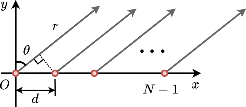
Figure 1: Schematic diagram of linear array radiation.
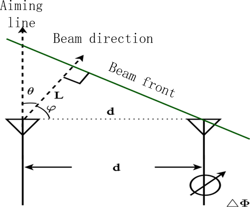
Figure 2: Diagram of phase analysis between adjacent components.
Figure 2 shows that the sum of and is 90. Thus we can calculate according to and , because . represents the variable distance of the wave propagation. The delay required for beam steering is equal to the time taken for the wavefront to traverse the distance . If is considered as a fraction of the wavelength, the phase delay can be replaced by this delay. The equation can be defined as the formula for . According to Fig. 2, the following equations can be derived:
| (1) |
| (2) |
| (3) |
where is the wavelength of the received signal. Then the sum of the radiation field strength of the array elements in the far region of the direction can be expressed as:
| (4) |
where is the radiation field strength of each element in the far field area, when is the same element is equal to , and the latter equation is established.
According to the summing formula and Euler formula, the above equation can be written as:
| (5) |
After taking the absolute value of the normalized isotropic element array, the array factor is expressed as:
| (6) |
When each array is not nondirectional and the field strength map is , the field strength map of the array becomes equation (7), that is, the product theorem of the direction diagram of the array antenna:
| (7) |
means that the unit factor is determined by the form and direction of the array element. It represents the radiation direction map of the array antenna and has nothing to do with the composition form of the antenna array. The array factor depends on the array arrangement, cell spacing, feed amplitude and phase, independent of the form and orientation of the array. Therefore, the array factor and the unit factor can independently determine the radiation performance of the antenna array, without interfering with each other. Because the antenna radiation surface size remains unchanged, the radiation performance of the array antenna is only related to the feed amplitude and phase.
B. Scheme
Depending on the number of targets to be powered, different transfer modes can be used. First, the subarray partitioning for the power transmission mode is discussed. Figure 3 (a) shows that an array of N antenna elements is divided into x parts, where x is the number of targets, and each subarray powers only its corresponding targets. In order to maintain beam steering capability and ensure a given receive power, the number of antenna arrays, N, should be greater than the number of targets, x. Based on the above strategy, one must increase the number of antennas of the WPT as the number of targets to be charged increases. This results in an increase in the size of the individual transmitters, which is unfavorable for the application. One way to alleviate this problem is to split the large array into several relatively small arrays, as shown in Fig. 3 (c). For example, in a large room with many sensors that need to be powered, place a transmitter array on each wall to power nearby sensors.
The other transmission mode that can solve the one-to-many WPT problem is time-division multiplexing using the entire antenna array. By exploiting the beam steering capability of the phased array, this mode can cyclically charge multiple targets within a time interval T, as shown in Fig. 3 (b). This strategy is recommended to minimize the size of the WPT array. However, a longer cycle time is required when multiple targets are present simultaneously. This results in a slower charge rate for each target. If the number of targets to be charged is too large, the charging time of each target will be slow and will not be able to keep up with its power consumption. From this point of view, the time-shared transmission mode cannot power too many targets at the same time. Therefore, in an extreme case, the multiple arrays approach is also applicable to the time-division strategy to overcome the above problem. As shown in Fig. 3 (d), the fixed charging interval for each charging node is T, and then each array charges the surrounding devices in turn.
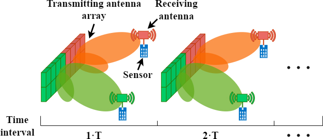

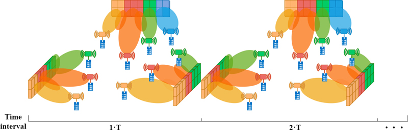
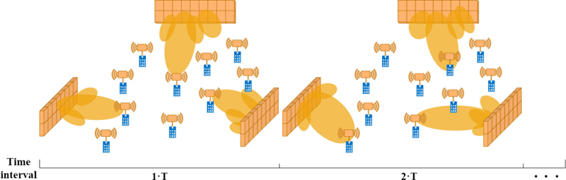
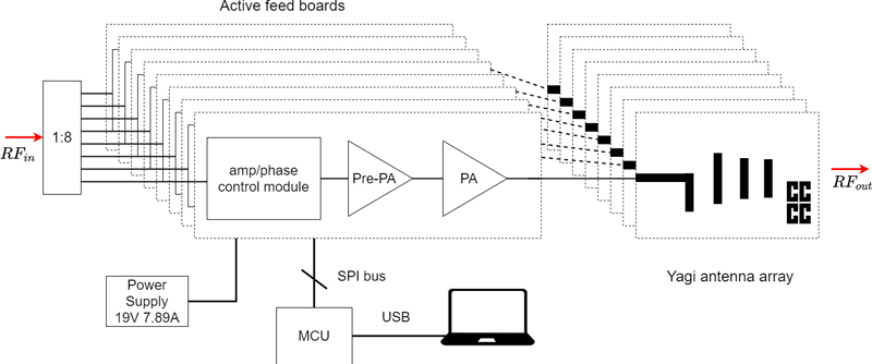
Figure 3: (a, b) Diagram of two targets power transmission at array-partition and time-division transmission mode, (c,d) diagram of multiple targets power transmission at array-partition and time-division transmission mode, and (e) functional block diagram of the system.
To take full advantage of the benefits and minimize the drawbacks, it is advisable to combine the two transmission modes rationally. In the case of charging multiple targets, the power transmission of the whole array and the subarrays can be carried out in a hybrid of time-division and array-partitioning. The allocation of each mode depends on the relationship between the received energy, the appropriate number of targets, the distance between the target and the antenna, and the number of array antennas.
In order to verify the feasibility of the transmission method, a 18 energy transmission array has been built in this paper, with transmission energy at a frequency of 2.4 GHz. Two modes are used to test the energy transmission of multiple targets.
III. DESIGN OF THE SYSTEM
The functional block diagram of the proposed single-to-multiple RF WPT system is shown in Fig. 3 (e). A 2.4 GHz signal is generated by the RF signal source and then transmitted to each circuit through the power divider. After the computer sets the waveform, each channel’s command is sent to the microcontroller unit (MCU). The MCU then controls the phase shift and attenuation of each channel. A two-stage RF power amplifier (PA) amplifies the RF signal after phase shifting. Each signal is amplified to 1 W and transmitted to free space via the antenna.
For verification purposes, we chose a 1 W RF PA to drive the antenna array, and the modular design makes it easy to replace different functional modules. The output power can be improved by simply replacing the PA with a higher PA.
A. Antenna design
The Friis formula for power transmission is:
| (8) |
where Pt is the power of the transmitting antenna, Gt is the gain of the transmitting antenna, Gr is the gain of the receiving antenna, Pr is the received power, is the operating wavelength and R is the distance between the transmitting and receiving antennas.
The gain of the antenna is positively correlated with the received power. The formula shows that the gain of the antenna is also essential to improve the efficiency of the energy transfer. Theoretically, the antenna that forms the array is omnidirectional, which makes the beam of the entire array more concentrated and more powerful. Therefore, in order to improve the efficiency as much as possible and to satisfy the omnidirectional wave lobe of a single antenna, the high-gain quasi-Yagi antenna is selected as the transmitting antenna of this system. It is a terminal array antenna that has evolved from the dipole antenna but has a higher gain than the dipole antenna [19, 20].
Based on this, a high-gain 2.4 GHz directional quasi-Yagi antenna suitable for this system is designed. Each part of the planarized quasi-Yagi antenna is replaced by a microstrip structure. A substrate dielectric layer separates two layers of metal conductors. The upper metal conductor layer is used as an electromagnetic radiator and the lower metal conductor layer is used as ground. The more directors the quasi-Yagi antenna has, the higher its gain. In this system, considering the overall size and the fact that the gain changes little when the number of directors is more than four, four directors are selected.
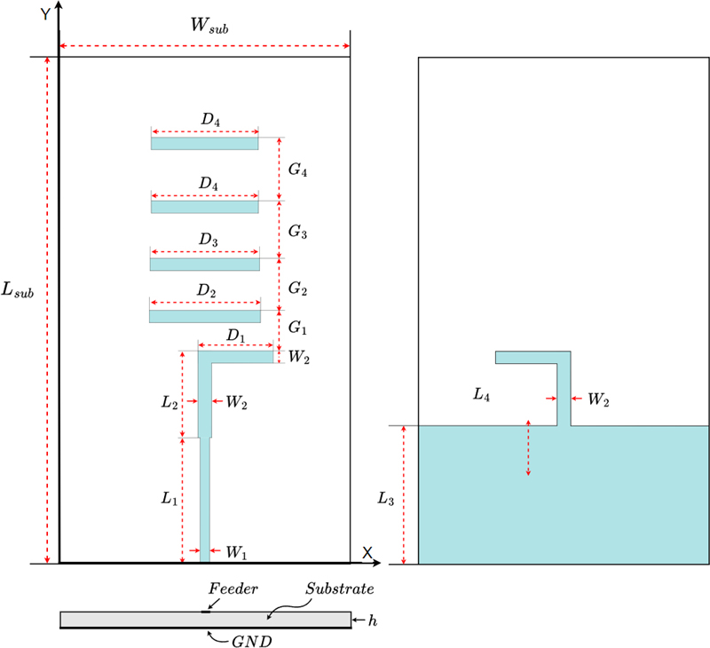
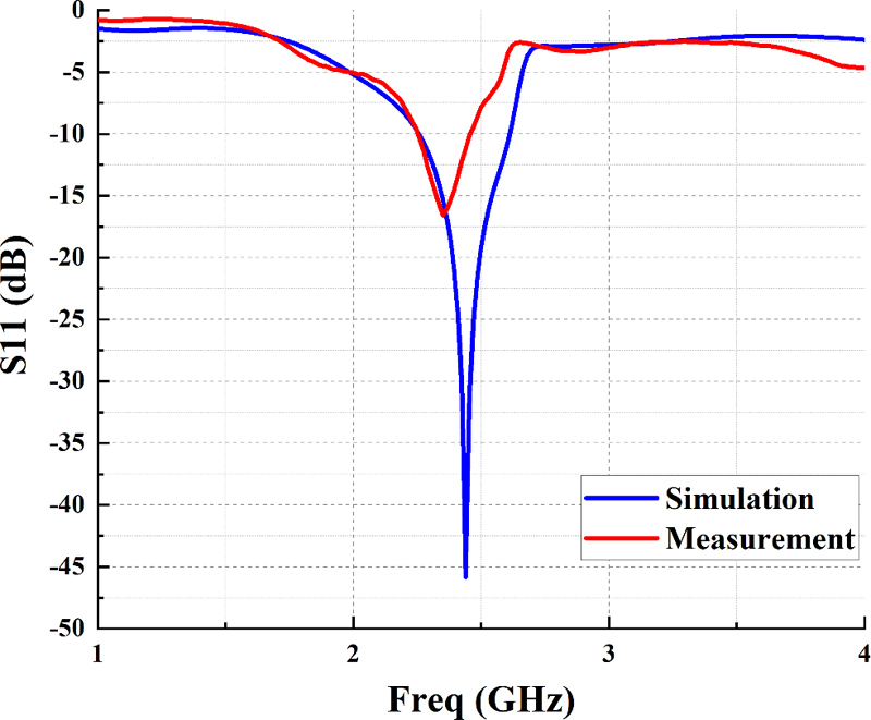
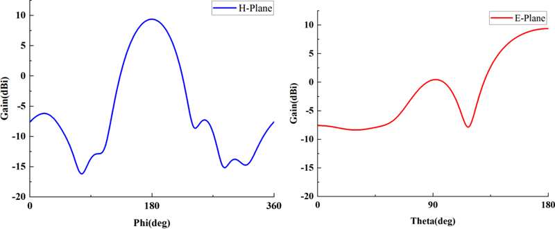
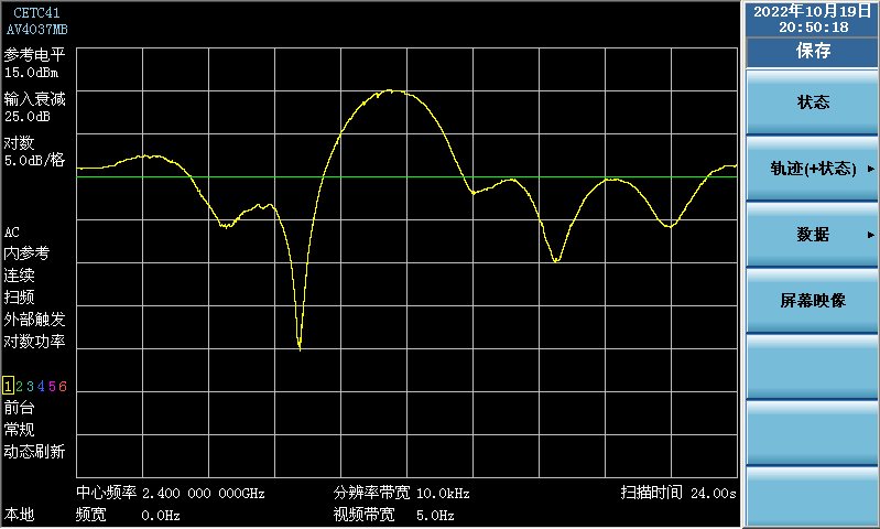
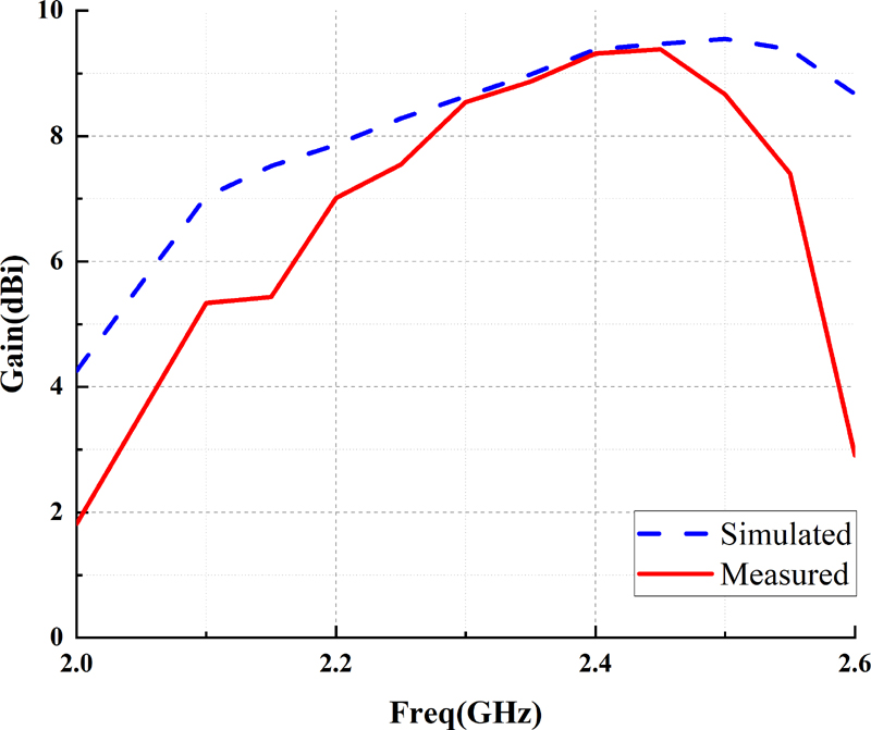
Figure 4: (a) Improved quasi-Yagi antenna with SSRR, (b) simulated and measured S11 of antenna, (c) simulated radiation patterns of antenna at 2.4 GHz, (d) measured radiation patterns of antenna at 2.4 GHz, and (e) the simulated and measured gain of the antenna.
The gain of the microstrip quasi-Yagi antenna is improved by the single split-ring resonator (SSRR), which acts as a special function of the pilot in front of the upper transmitting direction of the quasi-Yagi antenna. SSRR is a magnetic resonator consisting of a single open ring. Studies have found that it can be used to construct antennas and other microwave devices to obtain advantages such as high gain and good directivity [21].
The geometric structure of the improved antenna is shown in Fig. 4 (a). The high gain quasi-Yagi antenna based on SSRR can effectively reduce the return loss and improve the gain under the premise of ensuring the antenna size and bandwidth. Table 1 shows the parameters of the improved antenna with SSRR.
Table 1: Size parameters of the antenna (mm)
| h | |||
| 190 | 98 | 1.6 | 3.166 |
| 4.6 | 47.258 | 32.6 | 57 |
| 17.442 | 19.455 | 21.645 | 17.25 |
| 3 | 5 | 7 | 2.2 |
| 25.3 | 37.528 | 37.068 | 36.16 |
| 12.8 | 2.9 | 8 | 22.8 |
Replacing the fourth director with the SSRR results in a slight increase in gain. The antenna with SSRR reduces the size and increases the gain compared to the antenna with five feeders.
The designed antenna is measured using the AV3656B vector network analyzer. The simulated and measured return loss results are shown in Fig. 4 (b). The results show that the measured return loss has little change, and the resonant frequency is 2.39 GHz. Compared to the simulation results, the resonant frequency is shifted to a lower frequency. The measured bandwidth is 0.35 GHz. The shifted center frequency could be caused by the drifted dielectric constant and thickness of the core material of the PCB during the manufacturing process.
In addition, as shown in Fig. 4 (c), at 2.4 GHz, the radiation pattern radiates only to one end to reduce power loss, with a half-power beamwidth of 67. The measured image is shown in Fig. 4 (d) and there is not much deviation from the simulated image. Therefore, this antenna can focus and transmit electromagnetic signals. The simulated and measured gain of the antenna is shown in Fig. 4 (e). The gain of the designed antenna is 9.38 dBi at 2.4 GHz.
B. Wilkinson power divider design
To feed the proposed antenna array, a 18 Wilkinson power divider with an equal power distribution ratio is designed and optimized using the Advanced Design System (ADS) software. Figure 5 (a) shows the prototype of the power divider based on FR4 substrate.
It can be seen that the proposed power divider starts with a 12 substructure, which can be constructed with a three-port network (T-branch). A transmission line width with a characteristic impedance Z0=50 ohms and a quarter wavelength line with 70.7 ohms at a center frequency of 2.4 GHz can be calculated using the LineCalc tool from ADS. After obtaining the above initial value, the required 18 Wilkinson power divider is obtained by cascading the 12 power dividers in ADS.
The measured results of the Wilkinson power divider are shown in Figs. 5 (b,c). Ideally, the Sn1 (n is the number of outputs) of a 18 Wilkinson power divider is 9 dB. The results of the proposed power divider are around 9.2 dB at the operating frequency, which meets the requirements of our design. In addition, S11 is less than 15 dB, the interport isolation is greater than 20 dB, and the phase difference of the output ports is less than 1.189.
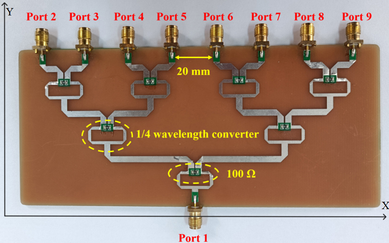
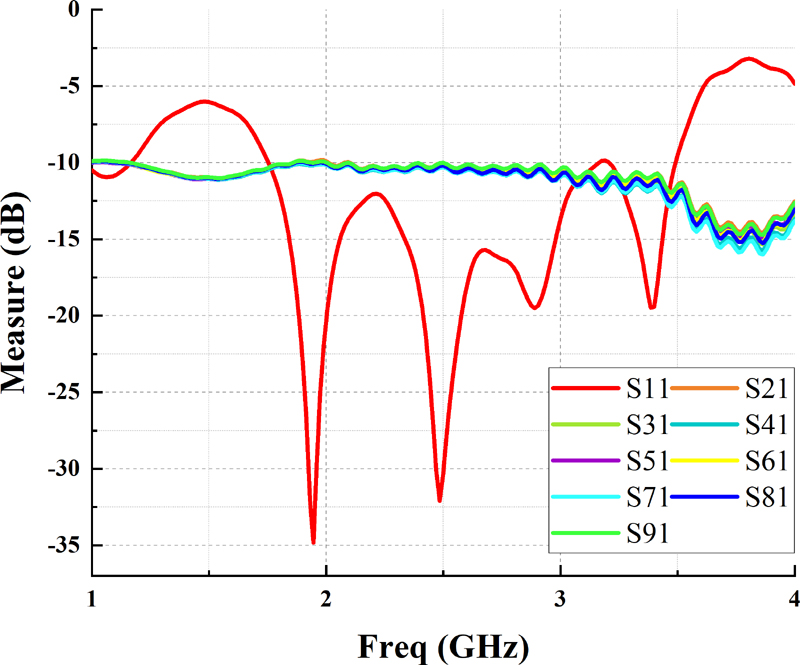
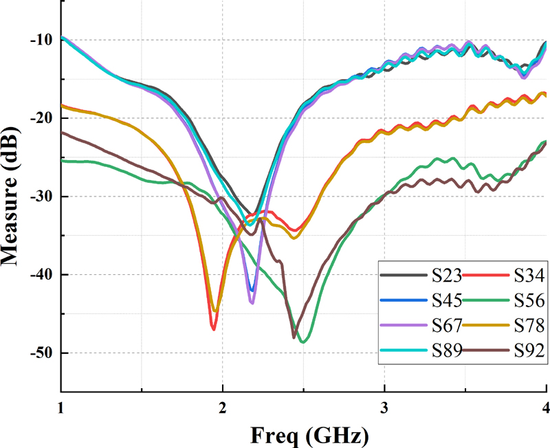
Figure 5: (a) Physical diagram of 18 Wilkinson power divider, (b) measured output port insertion loss and S11, and (c) measured isolation of each port.
C. Phase shift and amplifier circuit design
The selected PE44820 is the digital phase shifter that can achieve control accuracy of 1.4 within 360 at 8-bit resolution. The RMSE of phase and amplitude is 1.0 and 0.1 dB, respectively, the frequency range is 1.1-3.0 GHz, and the input third-order intercept is +60 dBm with high linearity. In addition, the integrated digital control interface supports serial and parallel programming of the phase setting, which facilitates cascade design and meets the design requirements of the system.
The matching design using ADS matched all RF signal lines to 2.4 GHz and impedance matching to 50 to minimize losses in the front and rear paths. Then, to realize the SPI bus control timing of the phase shifter and attenuator, the serial communication control is used to reduce the I/O port, the circuit port is designed in a cascade mode; where the phase shifter is the hardware SPI control, and the attenuator is the software SPI control. To realize the software addressing of the attenuator, the 74HC238 decoder is extended. The schematic and physical diagram is shown in Fig. 6.
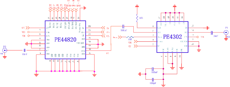
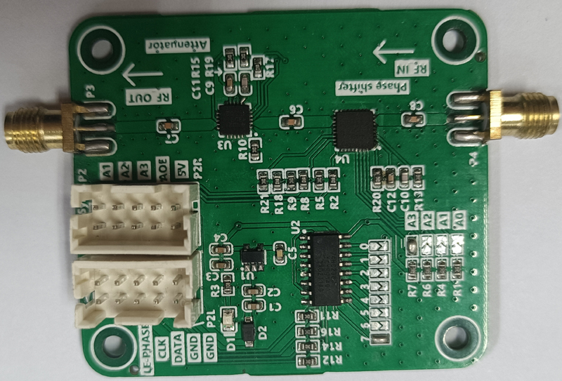
Figure 6: (a) Circuit schematic and (b) photo of phase shift attenuation module.
The parameters of the phase shift attenuation module were measured by the AV3656B vector network analyzer, as shown in Fig. 7, with 15 dB at 2.4 GHz, and the bandwidth was 1.14.4 GHz.
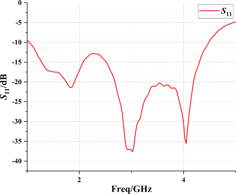
Figure 7: parameters of phase shift attenuation module.
With a step of 45and a step of 0.5 dB, respectively, the vector network test results are obtained as shown in Fig. 8. The relative phase error of the module is 1.2 3.8, the relative amplitude decay error is within 0.0056-0.0109 dB, which is within an acceptable range, and the main lobe of the beam has a certain width to accommodate this error value.

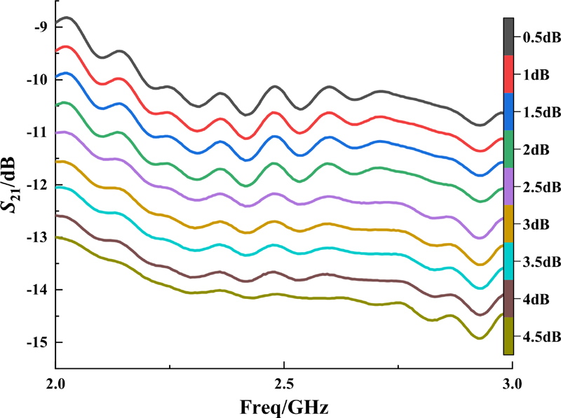
Figure 8: (a) Phase shift and (b) attenuation of the module.
In order to output the power of 1 W to the antenna end, a two-stage RF PA structure is adopted. A preamplifier SBB5089 with high linear gain and a RF PA SKY65135 with higher gain of 33 dB are designed as shown in Fig. 9. After the signal is amplified by a two-stage PA, a power of 30 dBm is radiated through the antenna.
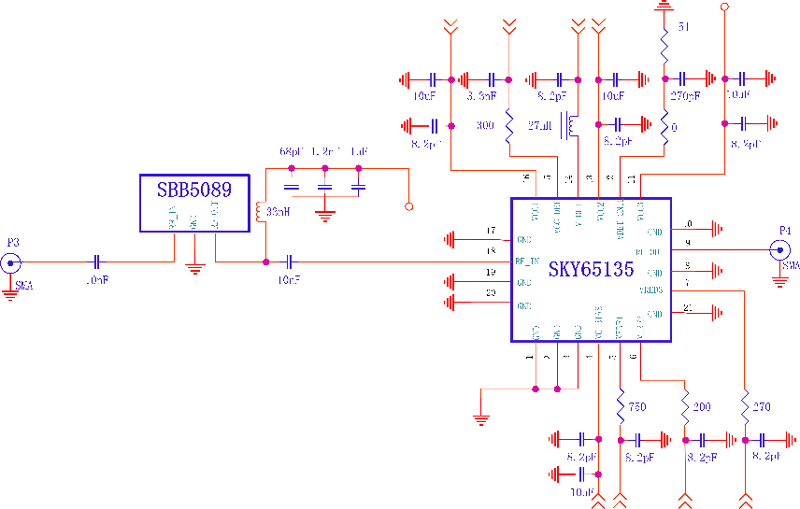
Figure 9: Schematic of RF power amplifier modules.
IV. EXPERIMENT AND DISCUSSION
To verify the beam steering capability, we set up an experimental platform for data acquisition as shown in Fig. 10 (a). The experimental platform includes an RF source, transmit array, receive antenna, spectrum analyzer, MCU and computer interface. Note that the transmit array and receive antenna are mounted separately on a rotator and slider. This makes it easy to measure the radiation performance under different angles and operating modes.
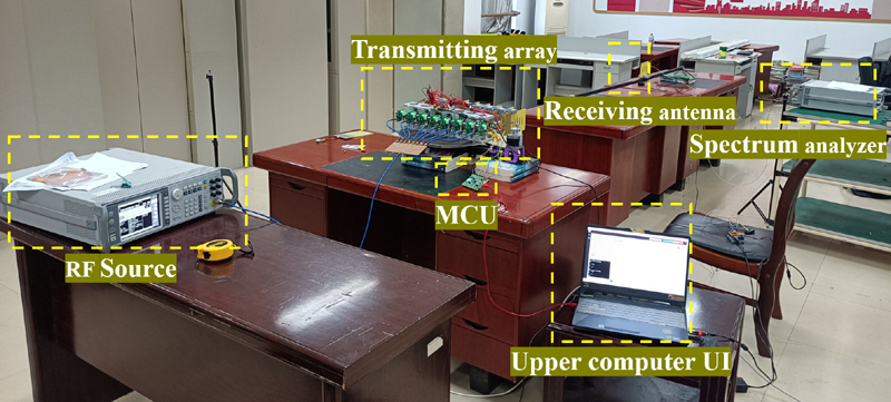
Figure 10: (a) Experimental platform for data acquisition, (b) simulated and measured radiation patterns of time-division transmission mode, and (c,d) simulated and measured multi-beam radiation pattern of array-partition mode at two targets in direction of 60 and 130, respectively, and three targets in direction of 60, 90 and 110, respectively.
Figure 10 (b) shows the simulated and measured radiation patterns of the time-division multiplexed transmission mode, where the power is cycled at 1-minute intervals to targets located at 0, 10, 20, 30, and 40 at a distance of 3 meters. Although the measured side lobe is larger than the simulated one, the main lobe is essentially the same as the corresponding angle of the simulation.
As described in Section II, for the multi-target loading scenario, we can use the full array single beam by the time division mode or use the array partition mode. The array partition mode has real-time performance, and the subarray division of a one-dimensional array is simple. This system adopts the technique of evenly dividing the array according to the number of receivers. For even-numbered targets, the transmit antenna array can be evenly divided into even-numbered parts. For odd-numbered targets, the transmit antenna array separates more antennas for distant targets based on the even division.
Figure 10 (c) shows the received power and simulated radiation patterns of the antenna array after placing two targets at a distance of 3 meters at 60 and 130, respectively. Figure 10 (d) shows the received power and simulated radiation patterns of the antenna array after beamforming at three target nodes at a distance of 3 meters at 60, 90 and 110. There are some differences between the test results and the simulation results, mainly because the channel amplitude and phase consistency of the system design is different from the simulation situation. The energy reflection caused by the test environment will also cause some deviation in the results. However, considering the practical charging situation, our system can still meet the charging demand at the required angle.
The performance comparison between this system and the WPT system proposed in the current relevant literature is shown in Table 2.
Table 2: Comparison with other reported WPT systems
| Refs. | Antenna Types | Operating Frequency | Single Antenna Gain | RF OutputPower(Distance) | Output Power | Number of Arrays | Phase-Controlled Mode |
| [22] | Patch antenna | 2.45 GHz | 6.64dBi | 4 m | N/A | 624 | Retrodirective array antenna(RDA) |
| [23] | Patch antenna | 2.4 GHz | 21dBi (Array gain) | 2 m | N/A | 44 | Phased arraycontrol |
| [24] | Patch antenna | 5.8 GHz | – | 10 m | 2.5 dBm | 88(44) | Single direction transmission |
| [25] | Patch antennas | 2.45 GHz | 5.9dBi | 1 m | 10 dBm | 161 | Retrodirective array antenna(RDA) |
| This work | Quasi-Yagi antenna | 2.4 GHz | 9.38dBi | 3 m | 7.5 dBm | 18 | Phased arraycontrol |
V. CONCLUSION
In this paper, a single-to-multiple WPT system based on phased array is designed. A novel quasi-Yagi antenna with SSRR is proposed for power transmission to increase the gain and reduce the size, with a gain of 9.38 dBi and a bandwidth of 0.35 GHz. A 18 Wilkinson power divider is then designed to construct an antenna array. Two transmission modes of the phased array are constructed so that the whole antenna array can transmit power by array division or time division, with a transmission power of 7.5 dBm at a distance of 3 meters. Experiments have verified that this transmission system can transmit power to multiple targets and achieve the effect of one-to-multiple wireless energy charging. Based on this design, the high-gain multi-mode phase-controlled WPT system can be applied to the power supply occasions of low-power electronic devices such as multi-sensor nodes in the IoT and has broad application prospects.
ACKNOWLEDGMENT
A Project Funded by the Priority Academic Program Development of Jiangsu Higher Education Institutions.
REFERENCES
[1] X. Bai, T. Ali, and L. Xu, “An antenna capable of harvesting radio frequency, vibration, and light energy based on piezoelectric and solar film materials,” Int. J. RF Microw. Comput.-Aided Eng., vol. 32, no. 2, Feb. 2022.
[2] M. Z. Chaari and R. Al-Rahimi, “Energized IoT devices through RF wireless power transfer,” in 2021 International Symposium on Electrical and Electronics Engineering (ISEE), Ho Chi Minh, Vietnam, pp. 199-203, Apr. 2021.
[3] C. Shao, H. Roh, and W. Lee, “Next-generation RF-powered networks for Internet of Things: Architecture and research perspectives,” J. Netw. Comput. Appl., vol. 123, pp. 23-31, Dec. 2018.
[4] W. A. Indra, S. G. Herawan Industrial, N. S. Zamzam, S. B. M. N. Fakulti, N. B. H. Fakulti, and F. Zuska, “Development of a guided drone powered by radio frequency energy harvesting,” in 2021 IEEE International Conference in Power Engineering Application (ICPEA), Malaysia, pp. 127-131, Mar. 2021.
[5] D. R. Kesari Mary, E. Ko, D. J. Yoon, S.-Y. Shin, and S.-H. Park, “Energy optimization techniques in underwater Internet of Things: Issues, state-of-the-art, and future directions,” Water, vol. 14, no. 20, Art. no. 20, Jan. 2022.
[6] X. Zhu, K. Jin, Q. Hui, W. Gong, and D. Mao, “Long-range wireless microwave power transmission: A review of recent progress,” IEEE J. Emerg. Sel. Top. Power Electron., vol. 9, no. 4, pp. 4932-4946, 2021.
[7] Y. Luo and L. Pu, “Practical issues of RF energy harvest and data transmission in renewable radio energy powered IoT,” IEEE Trans. Sustain. Comput., vol. 6, no. 4, pp. 667-678, Oct. 2021.
[8] N. Shinohara, “Trends in wireless power transfer: WPT technology for energy harvesting, mllimeter-wave/THz rectennas, MIMO-WPT, and advances in near-field WPT applications,” IEEE Microw. Mag., vol. 22, no. 1, pp. 46-59, 2021.
[9] Z. Popovic, “Near- and far-field wireless power transfer,” in 2017 13th International Conference on Advanced Technologies, Systems and Services in Telecommunications (TELSIKS), Nis, pp. 3-6, Oct. 2017.
[10] J. Huang, Y. Zhou, Z. Ning, and H. Gharavi, “Wireless power transfer and energy harvesting: Current status and future prospects,” IEEE Wirel. Commun., vol. 26, no. 4, 2019.
[11] Q. Hui, K. Jin, and X. Zhu, “Directional radiation technique for maximum receiving power in microwave power transmission system,” IEEE Trans. Ind. Electron., vol. 67, no. 8, pp. 6376-6386, Aug. 2020.
[12] J. H. Park, D. I. Kim, and K. W. Choi, “Analysis and experiment on multi-antenna-to-multi-antenna RF wireless power transfer,” IEEE Access, vol. 9, pp. 2018-2031, 2021.
[13] P. D. Hilario Re, S. K. Podilchak, S. A. Rotenberg, G. Goussetis, and J. Lee, “Circularly polarized retrodirective antenna array for wireless power transmission,” IEEE Trans. Antennas Propag., vol. 68, no. 4, pp. 2743-2752, Apr. 2020.
[14] K. Arai, K. Wang, M. Toshiya, M. Higaki, and K. Onizuka, “A tile-based 88 triangular grid array beamformer for 5.7 GHz microwave power transmission,” pp. 101-104, 2021.
[15] K. H. Jeong and N. Ghalichechian, “3D-printed 4-zone Ka-band Fresnel lens: Design, fabrication, and measurement,” IET Microw. Antennas Propag., vol. 14, no. 1, pp. 28-35, Jan. 2020.
[16] L. Zhu, J. Zhang, W. Han, L. Xu, and X. Bai, “A novel RF energy harvesting cube based on air dielectric antenna arrays,” Int. J. RF Microw. Comput.-Aided Eng., vol. 29, no. 1, p. e21636, Jan. 2019.
[17] T. Gao, X. Wang, L. Jiang, J. Hou, and Y. Yang, “Research on power distribution in multiple-input multiple-output magnetic coupling resonance wireless power transfer system,” Electr. Eng., vol. 103, no. 6, pp. 3217-3224, Dec. 2021.
[18] W. Zhou, M. Stead, S. Weiss, O. Okusaga, and Z. R. Huang, “Developing an integrated photonic system with a simple beamforming architecture for phased-array antennas,” Appl. Opt., vol. 56, no. 3, p. B5, Jan. 2017.
[19] W.-Y. Zhou, Z.-L. Mei, and M. Lu, “A compact quasi-Yagi antenna with high gain by employing the bent arms and split-ring resonators,” Int. J. Antennas Propag., vol. 2021, pp. 1-9, Feb. 2021.
[20] L. A. Feng, Z. Y. Heng, and W. Z. Jun, “Design of a broadband microstrip quasi-Yagi antenna with split-ring resonators,” in 2021 IEEE 6th International Conference on Computer and Communication Systems (ICCCS), Chengdu, China, pp. 819-822, Apr. 2021.
[21] A. Naghar, O. Aghzout, A. V. Alejos, D. A. Outerelo, and F. Falcone, “Improvement of notch performances for UWB monopole antennas using CSRR and SSRR,” in 2016 5th International Conference on Multimedia Computing and Systems (ICMCS), Marrakech, Morocco, pp. 456-458, Sep. 2016.
[22] C. An and H.-G. Ryu, “Power efficiency and antenna array dimension of middle range wireless power transmission,” in 2020 International Workshop on Antenna Technology (iWAT), Bucharest, Romania, pp. 1-4, Feb. 2020.
[23] K. Lee, J. Kim, and C. Cha, “Microwave-based wireless power transfer using beam scanning for wireless sensors,” in IEEE EUROCON 2019 18th International Conference on Smart Technologies, Novi Sad, Serbia, pp. 1-5, July 2019.
[24] X. Yi, X. Chen, L. Zhou, S. Hao, B. Zhang, and X. Duan, “A microwave power transmission experiment based on the near-field focused transmitter,” IEEE Antennas Wirel. Propag. Lett., vol. 18, no. 6, pp. 1105-1108, June 2019.
[25] S.-T. Khang, D.-J. Lee, I.-J. Hwang, T.-D. Yeo, and J.-W. Yu, “Microwave power transfer with optimal number of rectenna arrays for midrange applications,” IEEE Antennas Wirel. Propag. Lett., vol. 17, no. 1, pp. 155-159, Jan. 2018.
BIOGRAPHIES

Xue Bai was born in 1975. She received her Ph.D. degree in the field of Agricultural Information Technology from Jiangsu University in 2011. She is now an Associate professor in School of Electrical and Information Engineering, Jiangsu university, China. Her current research area is agricultural IoT and self-power technology for sensors.

Yanjiao Hou comes from Hulunbuir, Inner Mongolia, majoring in electrical engineering and graduated from Jiangsu University. She is currently working in the hardware field.

Leijun Xu was born in 1976. He received his Ph.D. degree in the field of RF & millimeter-wave integrated circuit from Southeast University in 2010. He is now a professor in School of Electrical and Information Engineering, Jiangsu university, China. His current research area is RF & THz integrated circuit for agricultural application.

Jianfeng Chen was born in 1987. Obtained a doctoral degree in Electromagnetic Field and Microwave Technology from Southeast University in 2021. He is currently a lecturer at the School of Electrical and Information Engineering, Jiangsu University, China. His current research field is electromagnetic fields and electromagnetic waves.

Yiyang Kong was born in 1998. He is currently a graduate student majoring in Agricultural Electrification and Automation at Jiangsu University. His research field is agricultural IoT and self-power technology for sensors.
ACES JOURNAL, Vol. 39, No. 10, 891–900
doi: 10.13052/2024.ACES.J.391007
© 2024 River Publishers