Diplexer Antenna for 5G Full-duplex Application
Hong Quang Nguyen1, Trong Toan Do2, Dinh Hai Truyen Hoang2, Quoc Cuong Nguyen1, and Minh Thuy Le1*
1School of Electrical and Electronic Engineering
Hanoi University of Science and Technology, 100000, Vietnam
2Viettel High Technology Industries Corporation
Viettel Group, 10000, Vietnam
thuy.leminh@hust.edu.vn
Corresponding Author
Submitted On: October 9, 2023; Accepted On: February 7, 2024
ABSTRACT
This work proposes a spiral filter-based diplexer antenna for dual-band full-duplex 5G application in C-band. The shared radiator is formed by a cross-shape Yagi-Uda antenna. The dual-band full-duplex characteristic is obtained by applying a diplexer with two different band-stop filters (BSFs) based on a high-order rectangular spiral-shaped open-stub filter. The proposed diplexer antenna is suitable for modern 5G full-duplex communication system applications with a small frequency ratio and high isolation between two ports by applying a Wilkinson power divider. The diplexer antenna is designed, fabricated, and measured, showing good performance of channel isolations of 27 dB/23 dB and the antenna gain of 4.7 dBi/4.2 dBi at two operation bands from 3.56 GHz to 3.68 GHz and from 3.72 GHz to 3.83 GHz covering the required 100 MHz maximum bandwidth in C-band while its frequency ratio is only 1.04.
Index Terms: Bandstop filter, diplexer antenna, dualband antenna, full duplex, small frequency ratio.
I. INTRODUCTION
Full-duplex communication allows a device to transmit and receive signals at the same time. It can potentially increase capacity of the system and contribute to minimize the latency [1]. In the terminal devices, the full-duplex antenna enables transmitting and receiving signals using a shared radiator-based antenna. However, the main challenge in the full-duplex antenna is the interference between the transmitter (Tx) and receiver (Rx) when they operate at the same time on the same frequency band or close frequency bands [2, 3]. It has been receiving many studies to solve this problem [4–9]. In [4], a duplexing antenna is developed and denoted based on a dual-band slot antenna. The bandwidths are 6.2% and 11%, with a frequency ratio of 1.48, defined by the high band’s center frequency divided by the low band’s center frequency. The isolation between Tx and Rx is higher than 20 dB. A dual-port dual-band antenna with an integrated duplexer and filter working at 4.3 GHz and 6 GHz was proposed in [5]. The proposed antenna showed a high isolation of 30 dB with a frequency ratio of 1.39. However, it required three substrates, leading to a complex design process. In [6], the dual-band patch antenna is achieved by coupling a square patch with a hairpin resonator through a slot in the ground, and the frequency ratio is just 1.14. However, these structures are complex, with high insertion loss because they used the resonators for higher-order filters. In addition, multi-substrates lead to high-cost fabrication processes. In [8], a highly integrated dual-band duplex antenna for the base station was proposed using a cross-dipole antenna. The diplexer with a band-pass filter was integrated with a balun, which coupled a quarter-wavelength resonator operating at 3.5 GHz and 4.9 GHz, respectively. However, the isolation between two frequency bands is just 20 dB with a frequency ratio of 1.4. In [9], a low-profile single-layer duplex-filter antenna using a SIW-based cavity resonator was presented. Dual-band characteristics can be controlled by the slot-cum-loaded vias that half-mode SIW realized. Although it realized a small frequency ratio of 1.08, the isolation is just 21 dB. In most existing literature, the antenna and diplexer are integrated into a single inseparable module, namely a duplex antenna for more compact with small dimensions and high selectivity [5, 6, 10, 11]. However, they use high-cost substrates and multi-layers. Besides, these structures are more suitable for patch antennaapplications.
One band that has proven particularly highly contested is the C-band, parts of which have been identified by the International Telecommunications Union for International Mobile Telecommunications (IMT)services, more commonly called 5G in the 3.6 GHz band and fixed satellite service (FSS) earth stations operating in an adjacent frequency band of 3.8 GHz [12]. These two close bands may cause significant interference in designing a dual-band antenna for C-band full-duplex applications.
To overcome all these limitations, in this work, we propose a novel planar diplexer antenna with a minimal frequency ratio of 1.04 for dual-band full-duplex application in C-band. The diplexer antenna combines a diplexer and a wideband antenna element in a single layer for low-cost fabrication. Firstly, we design a wideband dipole antenna. Then, a diplexer is proposed using a Wilkinson power divider with two high-order spiral open stub filters to obtain high isolation between two close frequency bands. Note that using a diplexer will decrease the operating bandwidth, but the proposed antenna still covers the required 100 MHz bandwidth in C-band [13]. The contribution of the proposed work is as follows: (i) The Tx and Rx channels share a single Yagi-Uda antenna structure, making them more compact and flatter than separate radiation parts. (ii) The bent diplexer is presented with a compact size, adjustable frequency ratio by changing the stub length, and high Tx/Rx isolation. To the best of our knowledge, no dual-band antenna structure for complete duplex application in the open literature has a smaller frequency ratio than this work.
II. DIPLEXER ANTENNA DESIGN
A. Antenna element design
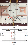
The initial dipole antenna is designed at the central frequency of 3.7 GHz, as antenna 1 in Fig. 1. The antenna evolution using V-arms dipole is shown in Fig. 1. To extend the bandwidth, the second dipole is added and rotated at an angle of with the first two arms of the initial dipole, namely V-arms. The proposed V-arms-shaped dipole antenna uses an integrated J-shaped balun. The gap between the two lines and the length of the balun’s shorted line are critical factors in adjusting impedance matching between a V-arms-shaped dipole and a J-shaped balun as antenna 3.
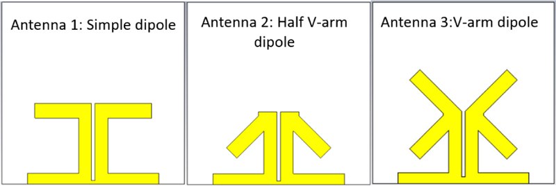
Figure 1: Evaluation process of the antenna design.
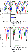
The bandwidth expansion ability of the proposed structure is described through the reflection coefficient in Fig. 2. As can be seen, the bandwidth increases 10% from 13.2% to 23.2%.
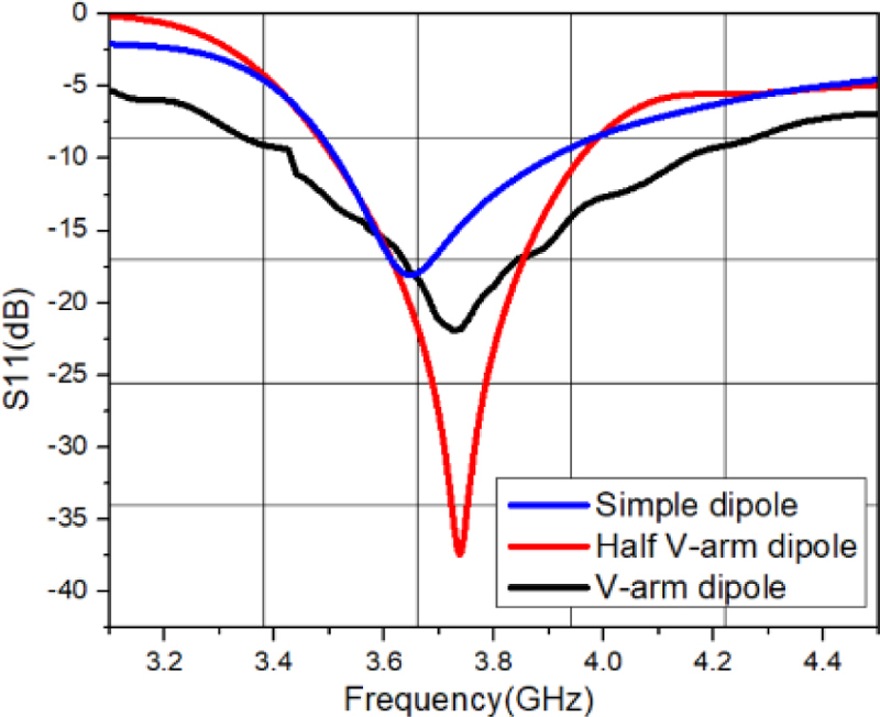
Figure 2: Simulated S11 of three design steps.
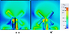
As shown in Fig. 3, the E-Field of the lower band is mostly determined by the two upper arms and the lower right arm. On the other hand, the E-Field distribution of higher frequencies is mainly created by the left V-arm and the gap between two V-arms.
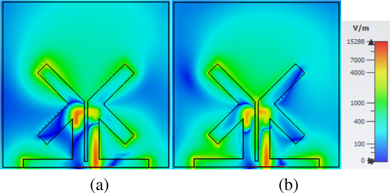
Figure 3: Electric field distribution of the proposed antenna at the metal-dielectric interface: (a) 3.5 GHz and (b) 3.9 GHz.
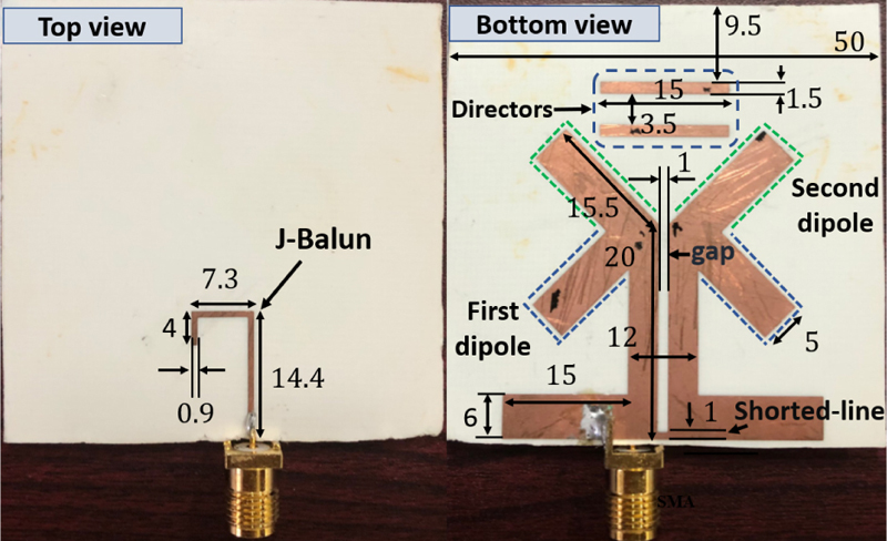
Figure 4: Proposed antenna element (all dimensions are in mm).
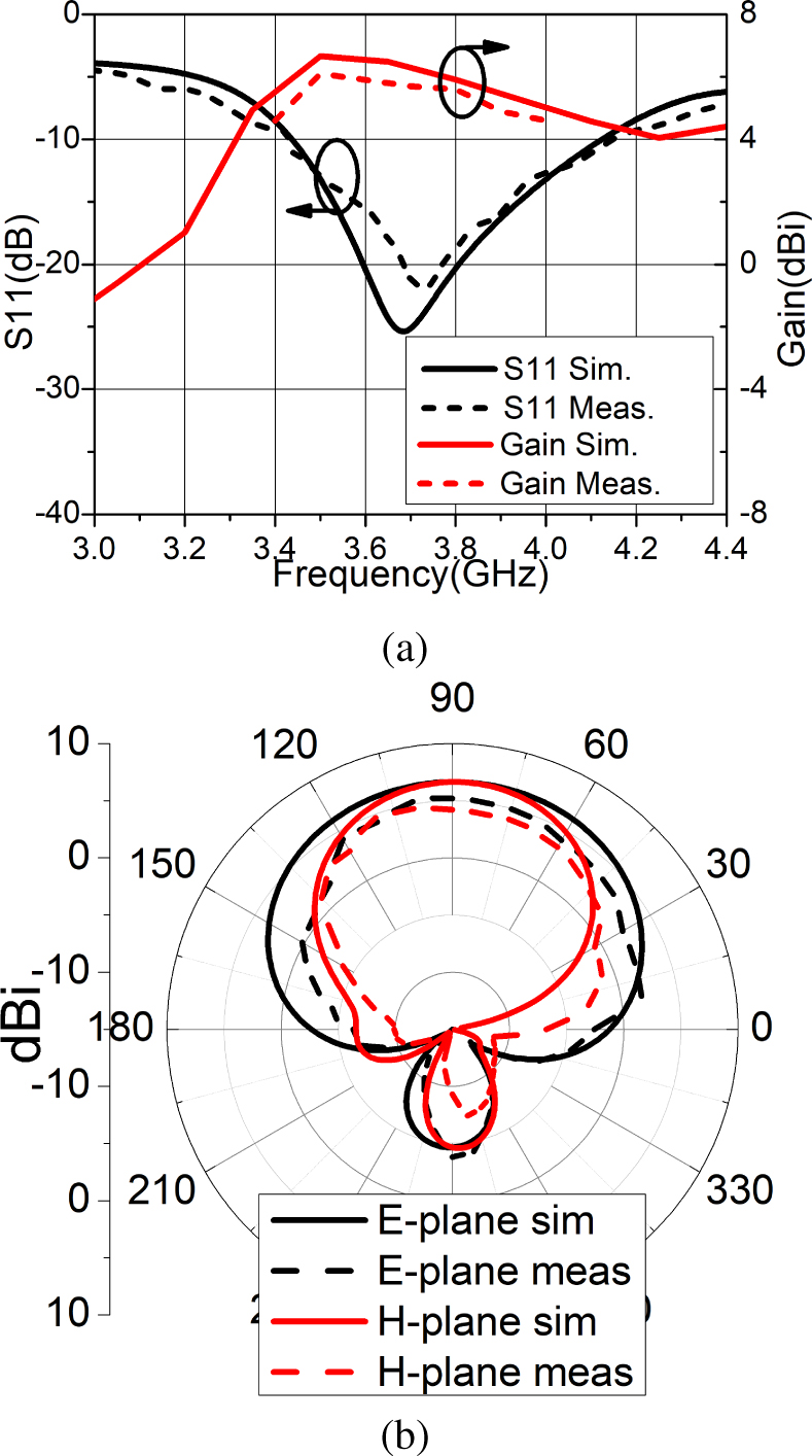
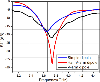
Figure 5: (a) The simulated and measured S11 result of a V-arms dipole antenna and antenna gain and (b) radiation pattern at 3.7 GHz.
To enhance the antenna’s gain up to 6 dBi, two directors are placed above the V-arms according to the Yagi-Uda antenna principle. The geometry of the printed dipole antenna using Roger 4003C substrate (and ) is shown in Fig. 4. Figure 5 (a) shows the simulated and measured results of the proposed printed V-arms dipole antenna and the gain simulation and measured result. It was found that there is an agreement between the simulated and the measured reflection coefficient. The simulated bandwidth of the proposed V-arms shaped dipole is 17.7% (3.45-4.12 GHz), and the measured result is 19% (3.41-4.13 GHz), respectively, fully cover the sub-6 5G frequencies band. The simulated gain of the proposed antenna is 5.64-6.64 dBi, while the measured value is 4.9-6 dBi over the operating bandwidth. The simulated radiation pattern is well matched with the measured one at the center frequency of 3.7 GHz, which indicates a directional radiation like a traditional Yagi Uda antenna, as in Fig. 5 (b). The half-power beam widths (HPBWs) are and in the E- and H-plane, respectively.
B. Diplexer design
A diplexer typically comprises two microwave bandpass filters (BPFs) at distinct center frequencies, and it was studied in the early 1960s by Matthaei et al. [14]. The desired diplexers are compact, low-cost, high isolation, planar and easily integrated into transceiver circuits [15–19]. In [15], a hairpin line diplexer with two wideband band-pass filters and high isolation was proposed. It comprises a T-junction connecting with two 5th-order hairpin line wideband band-pass filters operating at two bands of 3.1-4.9 GHz and 6.2-9.7 GHz. However, the isolation between the two channels is just 20 dB and poor S11 of -10 dB in the lower band. The hairpin line diplexer has considerable size and complexity limitations in design. In [17], a novel diplexer was proposed, which comprises two pairs of open-loop ring resonators with different resonant frequencies to couple with three microstrip lines of different lengths. However, its insertion loss is 2.73/3.68 dB, leading to low diplexer efficiency. Although numerous diplexers have been proposed, most focus on a large frequency ratio. However, for most modern 5G terminal devices, the TX and RX bands are incredibly close to each other. Thus, high isolation is challenging. This section proposes a compact, simple, high isolation design with a frequency ratio of nearly 1.0.
The proposed diplexer consists of two spiral-shaped filters working at two center frequencies of 3.6 GHz and 3.8 GHz, as shown in Fig. 6 (a). Because these two frequencies are close, applying BSFs instead of band-pass filters is more appropriate. The desired diplexer requires two narrow-operating bands to let the 3.6 GHz center frequency pass through and block the 3.8 GHz frequency and vice versa to other ports. Therefore, we use two high-order rectangular spiral-shaped open stubs for BSFs. The equivalent circuit of BSFs is shown in Fig. 6 (b). The open stub is equivalent to a serial circuit. and represent the inductance and the capacitance of the open stub, respectively. The ohmic loss is represented by a serial resistor that is inserted next to the inductor since the conductive material is non-ideal. The center stop-band frequencies are calculated by the inductor and the capacitor of the open stub, which can be adjusted by stub length. When the size of the open stub increases, the inductance and the capacitance become larger, resulting in a decrease in . The stub width is an essential factor to adjust the impedance matching of Port 3’ to Port 3.
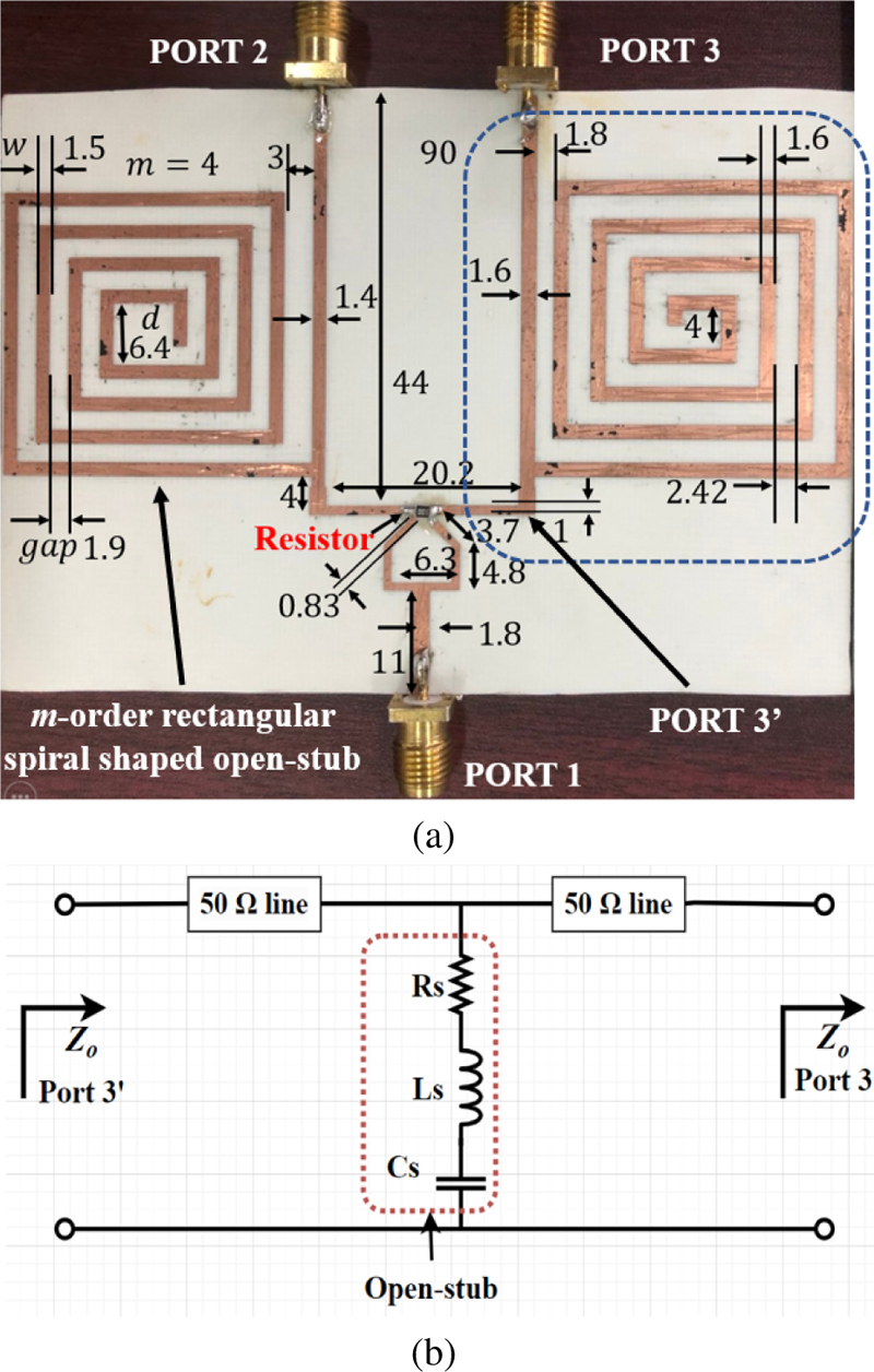
Figure 6: (a) Proposed diplexer (all dimensions are in mm) and (b) equivalent circuit of an m-order rectangular spiral shape open-stub.
BSF is formed by open stub having narrow bandwidth and excellent selectivity ( is the stub length). The filter’s bandwidth can be obtained as follows [20]:
| (1) |
where is the wavelength of the stopband in the dielectric substrate. is a natural number representing the filter level. When gets higher, the bandwidth becomes narrower. The stub length is carefully chosen depending on and . To the best transmittance of the desired transmission frequency, and the best reflection of the stopband the best chosen is calculated as follows:
| (2) |
The operating frequency of the diplexer depends on as shown in Fig. 7. For instance, if the blocked frequency is 3.6 GHz and the desired transmission frequency is 3.2 GHz, and the stub length, according to (2) will be 4 and for the best performance (as shown in Fig. 4, solid black line). This type of diplexer can control the frequency ratio between and , even if the frequency ratio is very close to 1, and it can be suitable for controllable dual-band transceiver or dual-band antenna applications and full-duplex applications. In this work, the diplexer operates at 3.6 GHz and 3.8 GHz, so is selected as 9 and each stub length is chosen for the best selectivity and rejection. With two long stubs, the overall size of the diplexer is bulky. It is crucial to miniaturize the stub size for a more compact diplexer.
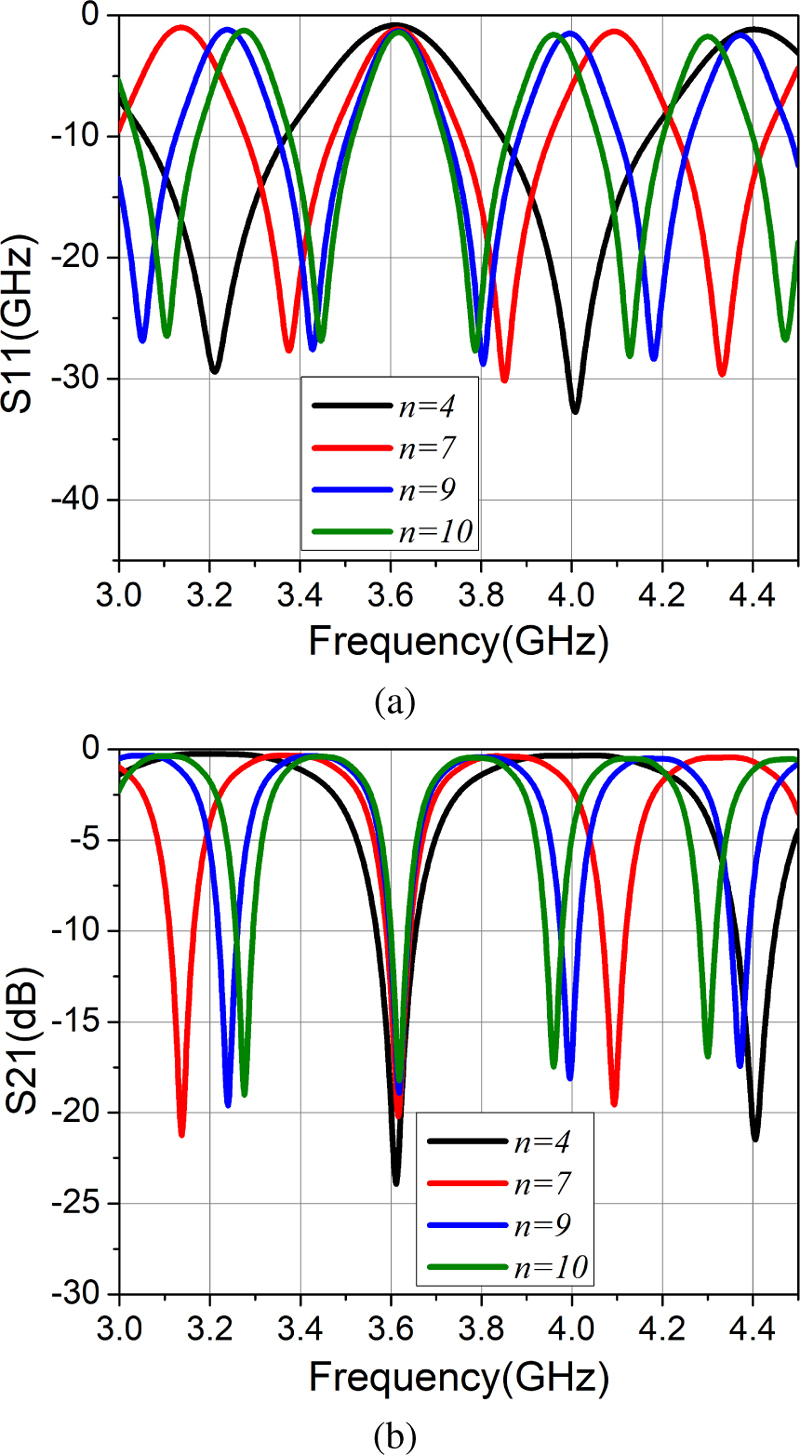
Figure 7: Simulated S-parameters of diplexer at different values of : (a) S11 and (b) S21.
Many previous works proposed various methods to miniaturize the size of the RF circuit [21, 22]. In this work, to reduce the total size, we proposed a bending method to turn the stubs into a rectangular spiral shape, as shown in Fig. 3 (a). The length of the rectangular spiral stub is calculated based on the arithmetic progression as follows:
| (3) |
where is the number of turns, is the width of the stub, and is the distance of two turns. is the length of starting coil as shown in Fig. 6 (a).
The dimensions of the rectangular stub are chosen with for compactness and good matching. , , and are optimized by numerical optimization. After completing the design of two filters based on 4-order open spiral stubs, they are connected to the V-arms dipole antenna through a Wilkinson power divider to form a diplexer. A Wilkinson power divider whose resistor is 100 is used to enhance the isolation between two ports. As shown in Fig. 6 (a), a diplexer prototype is fabricated with the dimension of 1.31.9 which is 19 times smaller than the original stubs, where is the wavelength of the center frequency in the substrate.
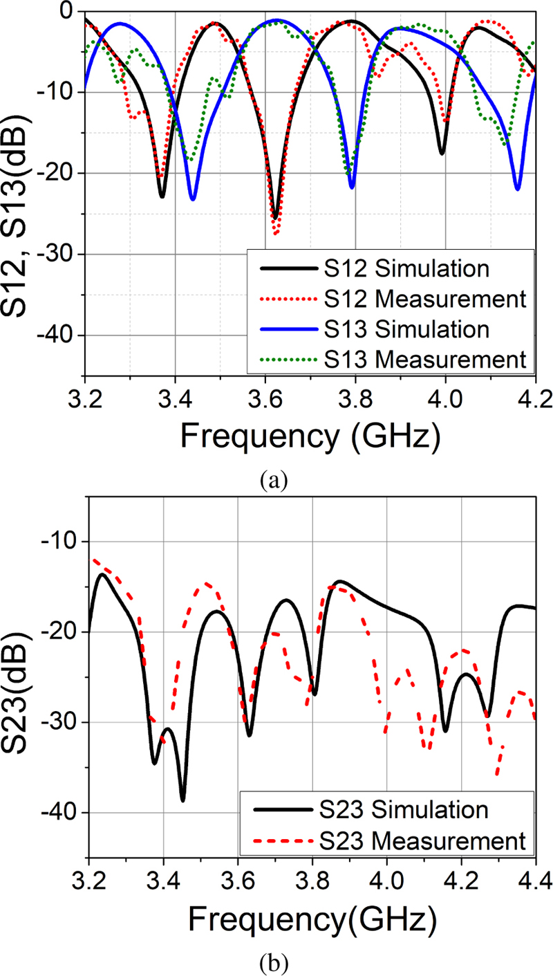
Figure 8: Simulated and measured S-parameters of the proposed diplexer: (a) S12 and S13 and (b) S23.
Figure 8 illustrates the simulated and measured S-parameters of the proposed diplexer. The diplexer shows a good filtering performance in the operating frequency bands. Port 2 shows the S21 at 3.6 GHz with -20 dB and 3.8 GHz with -1.9 dB of insertion loss, whereas Port 3 shows the S31 at 3.8 GHz with -21 dB and 3.6 GHz with -1.75 dB of insertion loss, respectively. The agreement of the simulation and measurement indicates that the diplexer has good band rejection and in-band transmission, except for a little frequency shift due to the fabrication tolerances and soldering technique. It also has good isolation of less than -20 dB in the 3.6-3.8 GHz band. The highest isolation reaches -30 dB at 3.64 GHz and -27 dB at 3.78 GHz. To our knowledge, this is the first time a diplexer with a frequency ratio below 1.05 has been proposed. The above results prove that the diplexer has a good performance and is suitable for full-duplex applications with two close frequency bands. The diplexer and antenna are then integrated to form the diplexer antenna. Because the bandwidth of the V-arms dipole antenna fully covers the bandwidth of the proposed diplexer, the proposed antenna has no extra 50 connector or transmission line, which avoids additional insertion loss due to the imperfect connection, as shown in Fig. 9.
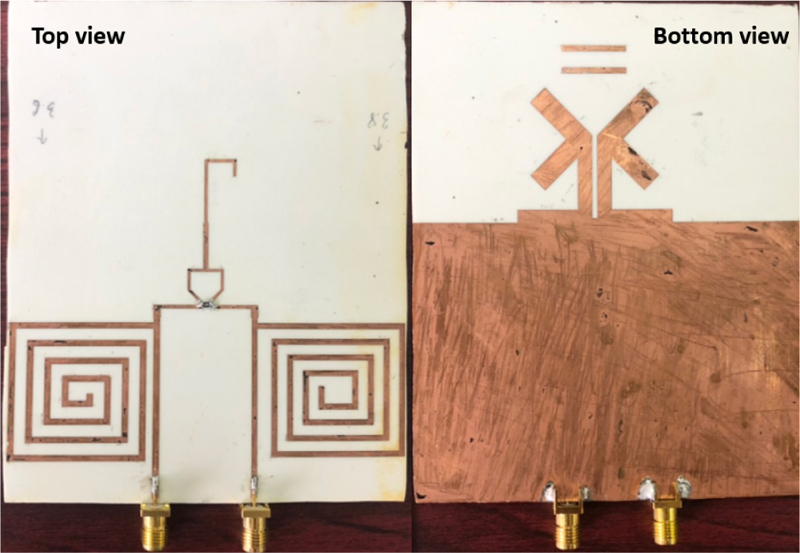
Figure 9: Fabricated proposed antenna.
III. RESULTS AND DISCUSSION
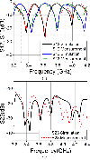
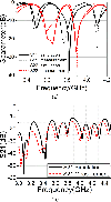
Figure 10 presents the simulated and measured S-parameter of the proposed diplexer antenna. The antenna has two operating bands excited by two corresponding ports (or two channels). The measured results agree well with the simulated results showing a bandwidth of 3% (3.72-3.83 GHz) in measurement and 3.3% (3.78-3.86 GHz) in simulation for channel-1 and a bandwidth of 3.3% (3.563.68 GHz) in measurement and 3.3% (3.57-3.7 GHz) in simulation for channel-2, covering the C-band for 5G and satellites, respectively. The achieved frequency ratio is 1.04. The two operating bandwidths are narrow because of two BSFs with higher order mode according to equation (1).
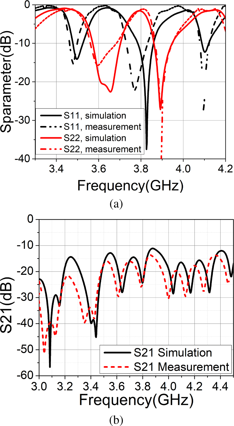
Figure 10: Simulated and measured S-parameter of the diplexer antenna: (a) S11 and S22 and (b) S21.
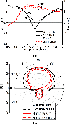
As shown in Fig. 10 (b), the antenna exhibits high isolation with the measured S21 up to -27 dB at 3.61 GHz and -23 dB at 3.8 GHz. It also has good isolation of less than -20 dB in the operation band. Figure 11 shows the radiation patterns at 3.6 GHz and 3.8 GHz with a good agreement between simulation and measurement. At 3.6 GHz, the half-power beam widths (HPBWs) are and in the E-plane and H-plane, respectively. The patterns also maintain slightly similar shapes within the operating bandwidth, when HPBWs of and are yielded at 3.8 GHz.
To provide a clearer understanding of the ability of frequency selectivity in two adjacent frequency bands of the antenna, the antenna gain is simulated and measured, as shown in Fig. 12. The results show that the antenna maintains high gains in the transmission bands and achieves near-null radiation at the stopbands. Although the gain of the diplexer antenna decreases compared to the antenna element, it maintains a small difference between the measured gain of 4.2-4.7 dBi and the simulated gain of 4.6–5.7 dBi.
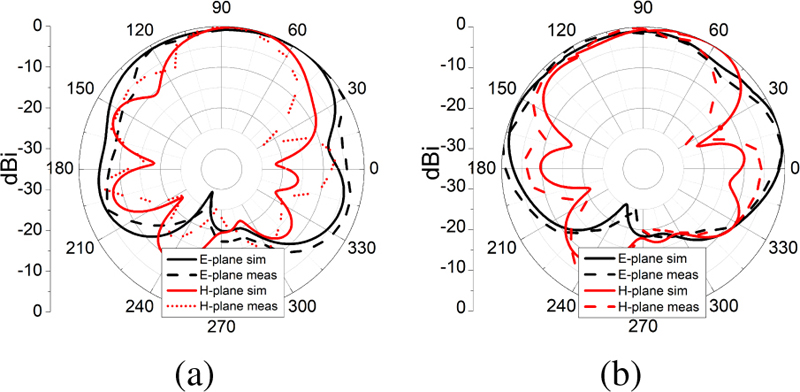
Figure 11: Simulated and measured radiation pattern of diplexer antenna: (a) 3.6 GHz and (b) 3.8 GHz..
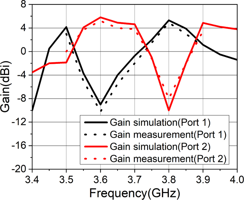
Figure 12: Simulated and measured gain of proposed diplexer antenna.
The related diplexer antennas are summarized in Table 1. In [4], the proposed duplexing antenna has high gain and compact compared to other works, but a high frequency ratio (FR) and lower isolation are reported. [6, 7] proposed a compact duplexing antenna and low frequency ratio, but using a two-layer substrate can lead to a high-cost and complex fabrication process. In addition, the proposed antenna in [6] can change the frequency ratio by modifying the foam thickness between two substrates, which results in a bulky system if the frequency ratio comes to 1. In [9], a low-profile single-layered duplex-filtenna scheme was proposed by using two feeds, and a common substrate integrated waveguide (SIW) cavity. Although the antenna used a high-cost substrate and SIW technique, the proposed antenna has the same results as our proposed antenna. Compared with the related works, the proposed solution is significant in terms of high isolation at the lowest frequency ratio (1.04). Note that the smaller the frequency ratio, the more challenged the high isolation level. Our diplexer antenna uses a single layer of Roger 4003C substrate, which is low-cost for fabrication, while all related works use double layers or a high-cost substrate of Duroid 5880. Moreover, the proposed diplexer can easily change the frequency ratio by modifying the stub length. In addition, the two ports are close to each other and enable easy connection to the transceiver in most terminal devices.
Table 1: Comparison between this work and related works
| Ref. | Freq./FR | Subs. | Gain | Iso. |
| [4] | 3.5/5.2, 1.48 | RT/Duroid 5880 single | 4.67/6.3 | 20.3 |
| [6] | 1.8/2.045, 1.14 | Roger 4003C double | 7/7.2 | 21/35 |
| [7] | 4.1/4.9, 1.19 | RT/Duroid 5880 double | 4.3/4.8 | 25/23 |
| [9] | 8.75/9.4, 1.08 | RT/Duroid 5880 single | 4.48/4.6 | 21.5/29.7 |
| This work | 3.6/3.8, 1.04 | Roger 4003C Single | 4.6/4.1 | 27/23 |
IV. CONCLUSION
In this paper, we propose a spiral filter-based diplexer antenna with low-cost, small frequency ratio, high isolation, and high selectivity advantages. The dual-band characteristics with a frequency ratio of 1.04 are achieved using a single printed V-arms dipole antenna integrated with the diplexer based on high-order rectangular spiral-shaped open-stub filters. The proposed diplexer exhibits good filtering performance, which could be used in an integrated RF front-end with reduced complexity, cost, and size with a small and flexible frequency ratio. By changing the length of the stub, the frequency ratio of the diplexer and the proposed antenna is easily adjustable, and the bandwidth of the in-band frequency selectivity and out-of-band rejection is adjusted. In addition, our proposed model may find potential uses in C-band full-duplex applications for 5G and satellites.
REFERENCES
[1] A. Sabharwal, P. Schniter, D. Guo, D. W. Bliss, S. Rangarajan, and R. Wichman, “In-band full-duplex wireless: Challenges and opportunities,” IEEE J. Sel. Areas Commun., vol. 32, no. 9, pp. 1637-1652, Sep. 2014.
[2] Z. Zhang, K. Long, A. V. Vasilakos, and L. Hanzo, “Full-duplex wireless communications: Challenges, solutions, and future research directions,” Proc. IEEE, vol. 104, no. 7, pp. 1369-1409, July 2016.
[3] K. E. Kolodziej, B. T. Perry, and J. S. Herd, “In-band full-duplex technology: Techniques and systems survey,” IEEE Trans. Microw. Theory Tech., vol. 67, no. 7, pp. 3025-3041, July 2019.
[4] Y. Xie, F.-C. Chen, and J.-F. Qian, “Design of integrated duplexing and multi-band filtering slot antennas,” IEEE Access, vol. 8, pp. 126119-126126, 2020.
[5] C.-X. Mao, S. Gao, Y. Wang, Y. Liu, X.-X. Yang, Z.-Q. Cheng, and Y.-L. Geng, “Integrated dual-band filtering/duplexing antennas,” IEEE Access, vol. 6, pp. 8403-8411, 2018.
[6] J.-F. Li, D.-L. Wu, G. Zhang, Y.-J. Wu, and C.-X. Mao, “Compact dual-polarized antenna for dual-band full-duplex base station applications,” IEEE Access, vol. 7, pp. 72761-72769, 2019.
[7] K.-Z. Hu, M.-C. Tang, Y. Wang, D. Li, and M. Li, “Compact, vertically integrated duplex filtenna with common feeding and radiating SIW cavities,” IEEE Trans. Antennas Propag., vol. 69, no. 1, pp. 502-507, Jan. 2021.
[8] J. Li, P. Hu, J. Chen, K.-D. Xu, C.-X. Mao, and X. Y. Zhang, “Dual-polarized duplex base-station antenna with a duplexer-integrated balun,” IEEE Antennas Wirel. Propag. Lett., vol. 21, no. 2, pp. 317-321, Feb. 2022.
[9] A. Kumar and A. A. Althuwayb, “SIW resonator-based duplex filtenna,” IEEE Antennas Wirel. Propag. Lett., vol. 20, no. 12, pp. 2544-2548, Oct. 2021.
[10] C.-X. Mao, S. Gao, Y. Wang, F. Qin, and Q.-X. Chu, “Compact highly integrated planar duplex antenna for wireless communications,” IEEE Trans. Microw. Theory Tech., vol. 64, no. 7, pp. 2006-2013, July 2016.
[11] C.-X. Mao, S. Gao, and Y. Wang, “dual-band full-duplex tx/rx antennas for vehicular communications,” IEEE Trans. Veh. Technol., vol. 67, no. 5, pp. 4059-4070, May 2018.
[12] J. R. Parker, I. D. Flood, and G. D. Carter, “Adjacent channel compatibility between IMT and ubiquitous FSS earth stations in the 3.4-3.8 GHz frequency band,” Wirel. Netw., vol. 27, no. 2, pp. 1103-1110, Feb. 2021.
[13] “5G frequency bands & spectrum allocations,” CableFree.
[14] G. L. Matthaei and E. G. Cristal, “Multiplexer channel-separating units using interdigital and parallel-coupled filters,” IEEE Trans. Microw. Theory Tech., vol. 13, no. 3, pp. 328-334, May1965.
[15] M.-H. Weng, C.-Y. Hung, and Y.-K. Su, “A hairpin line diplexer for direct sequence ultra-wideband wireless communications,” IEEE Microw. Wirel. Compon. Lett., vol. 17, no. 7, pp. 519-521, July 2007.
[16] M.-L. Chuang and M.-T. Wu, “Microstrip diplexer design using common t-shaped resonator,” IEEE Microw. Wirel. Compon. Lett., vol. 21, no. 11, pp. 583-585, Oct. 2011.
[17] C.-M. Chen, S.-J. Chang, C.-F. Yang, and C.-Y. Chen, “A simple and effective method fordesigning frequency adjustable balun diplexer with high common-mode suppression,” IEEE Microw. Wirel. Compon. Lett., vol. 25, no. 7, pp. 433-435, July 2015.
[18] C.-F. Chen, K.-W. Zhou, R.-Y. Chen, H.-Y. Tseng, Y.-H. He, W.-J. Li, and J.-H. Weng, “Design of microstrip multifunction integrated diplexers with frequency division, frequency selection, and power division functions,” IEEE Access, vol. 9, pp. 53232-53242, 2021.
[19] Y. Wu, L. Hao, W. Wang, and Y. Yang, “Miniaturized and low insertion loss diplexer using novel inter-digital capacitors and microstrip section inductors,” IEEE Trans. Circuits Syst. II Express Briefs, vol. 69, no. 11, pp. 4303-4307, Oct. 2022.
[20] M. Q. Dinh and M. T. Le, “Triplexer-based multiband rectenna for RF energy harvesting from 3G/4G and Wi-Fi,” IEEE Microw. Wirel. Compon. Lett., pp. 1-1, 2021.
[21] R. O. Ouedraogo, E. J. Rothwell, A. R. Diaz, K. Fuchi, and A. Temme, “Miniaturization of patch antennas using a metamaterial-inspired technique,” IEEE Trans. Antennas Propag., vol. 60, no. 5, pp. 2175-2182, May 2012.
[22] C. Sharma and D. K. Vishwakarma, “Miniaturization of spiral antenna based on fibonacci sequence using modified Koch curve,” IEEE Antennas Wirel. Propag. Lett., vol. 16, pp. 932-935, 2017.
BIOGRAPHIES

Hong Quang Nguyen was born in Hai Duong, Vietnam, in 1999. He received his B.Eng. degree in electrical engineering from Hanoi University of Science and Technology (HUST), Hanoi, Vietnam. He is currently a second year master student, major in electrical engineering, Hanoi University of Science and Technology. His current interests include millimeter-wave antennas, bio-based material microwave circuits, and RF energy harvesting.

Trong Toan Do was born in Hai Duong, Vietnam, in 1991. He received his Degree of Engineer in electronics and communication engineering from HUST, Hanoi, Vietnam. He has been working for Viettel High Tech RnD from 2014. He is currently a group leader of antenna team in 5G project in Viettel. His current research interests include wideband antennas, array antennas, and 5G beamforming.

Dinh Hai Truyen Hoang was born in Ha Tinh, Vietnam, in 1984. He received his Degree of Engineer in electronics and communications engineering from HUST, Hanoi, Vietnam. He has been working for Viettel High Tech RnD from 2010. He is currently a chief technology officer who takes care of 5G projects in Viettel. His current research interests include high speed circuits, RF high power and frequency amplifiers, antennas, array antennas, and 5G beamforming.

Quoc Cuong Nguyen received the engineer (1996) and M.S. (1998) degrees in electrical engineering from HUST, and the Ph.D. degree in Signal - Image - Speech - Telecoms from INP Grenoble, France, in 2002. He is a professor at the Department of Automation, School of Electrical and Electronic Engineering (SEEE). His research interests include signal processing, speech recognition, beamforming, smart sensors, and RF communications.

Minh Thuy Le was born in Vietnam. She received the B.E. and M.S. degrees in electrical engineering from the Hanoi University of Science and Technology (HUST), in 2006 and 2008, respectively, and the Ph.D. degree in optics and radio frequency from the Grenoble Institute of Technology, France, in 2013. She is currently a professor and a group leader of the Radio Frequency Group, School of Electrical Engineering and Electronic (SEEE), HUST. Her current research interests include built-in antennas, antenna arrays, beamforming, metamaterials, indoor localization and RF energy harvesting, wireless power transfer, and autonomous wireless sensors.
ACES JOURNAL, Vol. 39, No. 1, 31–38
doi: 10.13052/2024.ACES.J.390105
© 2024 River Publishers