A Rapid Single-view Radar Imaging Method with Window Functions
Wen Ming Yu1, Yi Ting Yang1, Xiao Fei Lu2, Chao Yang3, Zai Gao Chen3, and Tie Jun Cui1
1School of Information Science and Engineering, Southeast University
Nanjing, 210096, China
wmyu@seu.edu.cn, 230189062@seu.edu.cn, tjcui@seu.edu.cn
2Jiuquan Satellite Launch Center
Jiuquan, 732750, China
luxiaofei.2008@tsinghua.org.cn
3Northwest Institute of Nuclear Technology
Xi’an, 710024, China
yangchaophy@foxmail.com
Submitted On: October 16, 2023; Accepted On: February 28, 2024
ABSTRACT
Monostatic rapid single-view radar imaging technology is a technique that employs single incidence angle and single frequency point information to implement rapid monostatic radar imaging within a small angular field. Owing to its analytical expression, this technique can substitute the traditional frequency-angle-scanning imaging in a small angular range, facilitating the rapid generation of highly realistic radar imaging data slices for complex targets and environments. This technology has been significantly applied in scatter hotspot diagnostics and target recognition. In order to achieve the windowing effect equivalent to that of frequency-angle-scanning imaging, and to enhance the scattering feature of monostatic imaging while controlling sidelobes, this paper derives analytic windowed imaging formulas for monostatic radar. It then obtains analytical expressions for various typical monostatic windowing rapid radar imaging scenarios. This enables the monostatic rapid imaging technology to maintain high efficiency in its analytical expressions while achieving the windowing effect equivalent to traditional imaging. The validity and correctness of the analytical formula and software implementation have been confirmed through 1D, 2D, and 3D imaging verifications. This technology can provide a vast amount of training data for modern radars.
Index Terms: Radar imaging, single-view, window functions.
I. INTRODUCTION
Radar imaging can reconstruct target geometry and material characteristics through echoes and has a wide range of applications in geographic exploration, ocean observation, disaster prediction and military reconnaissance [1, 2, 3, 4, 5], etc. High-resolution one-dimensional distance imaging is often utilized for determining detonation points, while two-dimensional radar imaging is typically used for target recognition and remote sensing data classification [6]. Three-dimensional radar imaging is a crucial basis for radar feature identification in the current field of autonomous driving. How to obtain three-dimensional radar imaging data of the target and the environment is one of the hot research topics in the field of autonomous driving [7].
Traditional radar imaging technology is built upon the Fourier transform relationship between the electromagnetic distribution of the antenna aperture and far-field scattering, typically employing synthetic aperture methods to enhance azimuth resolution. From one dimension to two, and then to three, the utilization rate of imaging information is increasingly high. Superior imaging technologies, such as two-dimensional and three-dimensional, are gradually becoming practical with the advancement of hardware technology. In the field of autonomous driving, due to the all-weather characteristics of millimeter-wave radar, research on target characteristics technology based on three-dimensional millimeter-wave radar imaging is gaining increasing attention.
Radar imaging technology, based on electromagnetic scattering characteristic theory modeling, is a vital means of obtaining data on the radar scattering characteristics of targets and their environments. It has already found applications in military target identification and civilian remote sensing. Monostatic millimeter-wave radar imaging, originating from electromagnetic simulation technology, can significantly reduce the bandwidth and angular sampling expenses required for single-station imaging, enhancing the efficiency of obtaining imaging slice data. This technology was first applied to time-domain simulation of radar target scattering characteristics [8], rapidly obtaining time-domain echoes through the convolution of the analytical expression of target partition element time-domain responses with the signal. Subsequently, this technology was used in two-dimensional Inverse Synthetic Aperture Radar (ISAR) imaging [9, 10], and in recent years, applied to automatic target recognition [11, 12, 13] and urban remote sensing electromagnetic feature extraction [14].
The windowing operation is a standard procedure within radar imaging algorithms. Imaging represents the comprehensive broadband and angular information from the radar within the time and/or spatial domains. By applying a non-uniform window function prior to the Fourier transform, the spectral leakage effect of the Fast Fourier Transform (FFT) is mitigated. Concurrently, the windowing process is akin to executing a convolution operation in the time or spatial domains, which results in the broadening of the main lobe, thus reducing resolution. Implementing a non-uniform window prior to the Fourier transformation in the imaging of aperture data can effectively lower the sidelobe levels in individual cell imaging and enhance the visibility of target characteristics [15, 16]. Monostatic rapid imaging is mainly used for feature extraction and strong scattering diagnosis of targets. The literature [17] attempted to introduce a window function into the rapid single-view imaging algorithm, but it directly truncated the sinc function in time domain, which could not reproduce the conventional process of obtaining radar images through Fourier transformation after window function weighting.
II. SINGLE–VIEW RADAR IMAGING METHOD
For ease of understanding, this paper describes the imaging principle of single-view millimeter-wave radar using the most representative two-dimensional imaging as an example. The definition of single-view millimeter-wave imaging radar still adheres to the traditional frequency-angle-scanning radar imaging, that is, the received field value of the radar and the radar image constitute a Fourier transform pair [18]:
| (1) |
Here, represents the image or target function in the image domain coordinates , is the spatial frequency in the radar line of sight direction, and it satisfies , so is the propagation constant of the electromagnetic wave. is the spatial frequency in the direction orthogonal to the line of sight , and . can be the direction indicated by azimuth or elevation angle . is the received radar echo electric field value.
The process of sweep-frequency scanning radar imaging is to use FFT to solve the above formula (1). This process requires obtaining the target radar echo field value . In commonly used monostatic radars, it is necessary to implement monostatic wideband small-angle scanning in simulation modeling, especially for two-dimensional and three-dimensional imaging. To cover the entire target or scene, the number of scanning samples can reach the order of and , respectively. Document [9] first gave the monostatic radar distance imaging formula, greatly improving the imaging efficiency. In order to keep the formula consistent with the windowed imaging formula below, the following simple derivation is given using the previous definition: Assume that any complex target is described by a geometric model represented by triangle collection . The expression of the far-field scattering field illuminated by a plane wave is as follows [19]:
| (2) |
Here, represents the polarization term, where and denote the wave vectors of incident and reflected waves for any surface element with the normal vector , respectively, and is the wave vector constant. is the amplitude of at source point. is the distance from observation point to the origin. The term is the phase integral for a unit surface element.
| (3) |
where represents the position vector of a certain point on the surface element , which serves as a phase reference point. The term represents the phase shift of this surface element relative to the origin of the coordinate system. represents the scattering shape factor of this surface element. By substituting equation (2) into the imaging formula (1), when , the variation of with can be ignored.
| (4) |
Under the usual small-angle imaging assumption, ignore the variation of with or , , where represents the wave number corresponding to the center frequency and represents or . Let and , which represent the line of sight distance and horizontal distance from each triangular reference point to the coordinate origin, respectively.
When calculating the far field, let the amplitude distance be 1, and the phase take , so:
This equation indicates that the target radar image or target function can be composed of the superposition of sinc functions centered on each triangular element reference point. The terms sinc and sinc are referred to as expansion functions. Because the derivation process assumes a small angle, it’s easy to understand: one-dimensional imaging only uses sinc as an expansion function, while three-dimensional imaging requires an additional expansion function similar to .
Figure 1 provides a comparison between the three-dimensional imaging of a single-view radar of an aircraft and the three-dimensional imaging of a frequency scanning angle radar. Combined with more experiments, it shows that for complex targets, the rapid single-view imaging, whether in terms of the position of strong scattering points or the intensity of calibrated strong scattering points, is the same as that of frequency scanning angle. However, the former has much higher computational efficiency and is very suitable for strong scatter diagnosis and target feature extraction.
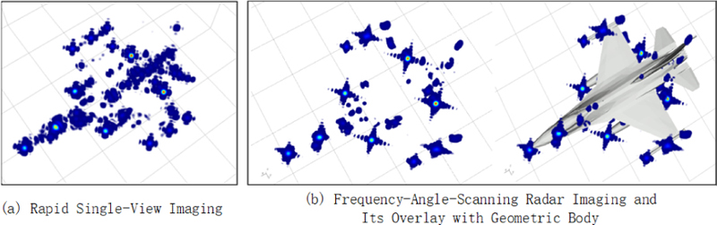
Figure 1: Comparison of rapid single-view imaging and frequency-angle-scanning imaging.
III. WINDOWED SINGLE-VIEW RADAR IMAGING TECHNIQUE
According to the definition of windowed normalized radar imaging in Cartesian coordinates [18], we have:
| (5) |
where represents the target scattering function, is the distance from the target center to the observation point (in the far field, it is infinite), and , represent the scattered field and the incident field at the observation point, respectively. is the window function, and is the amplitude normalization factor [18]. After changing equation (5) to one-dimensional and three-dimensional integrals, we get the windowed normalized one-dimensional and three-dimensional imaging. For small angle imaging,we have:
When is a rectangular window, we have:
For traditional frequency-angle-scanning imaging, the aforementioned equation can be calculated through FFT. For rapid single-view imaging, it needs to be transformed into an analytical expression. Referring to the derivation in section 2, we can get the single-view radar imaging formula weighted by a rectangularwindow:
where , , is the center frequency point of bandwidth , , , , and and are, respectively, the projections of the triangular reference phase vectors that make up the target in the and directions.
After similar derivation, Table 1 gives the key parameters of corresponding to commonly used window functions. For uniformity, all windowed single-view radar imaging formulas in the table are written in the following mode:
where the key variables and represent the expansion functions in the and directions, respectively, and represents the weighting coefficient, specifics are shown in Table 1. represents real part of a variable. is error function. Formulas of can be obtained by replacing to in .
Table 1: Key quantities for rapid single-view radar imaging with different window functions
| Type | ||
|---|---|---|
| Rectangle | ||
| Triangle | ||
| Welch | ||
| Sin | ||
| Hann | ||
| Hamming | ||
| Blackman | ||
| Gauss |
IV. NUMERICAL EXPERIMENTS
To verify the effect of windowed single-view radar imaging, the windowing effect is demonstrated below using the one-dimensional distance image of a dihedral angle and two- and three-dimensional radar imaging of a certain aircraft as examples. The results are shown in Figs. 2, 3, 4, respectively.
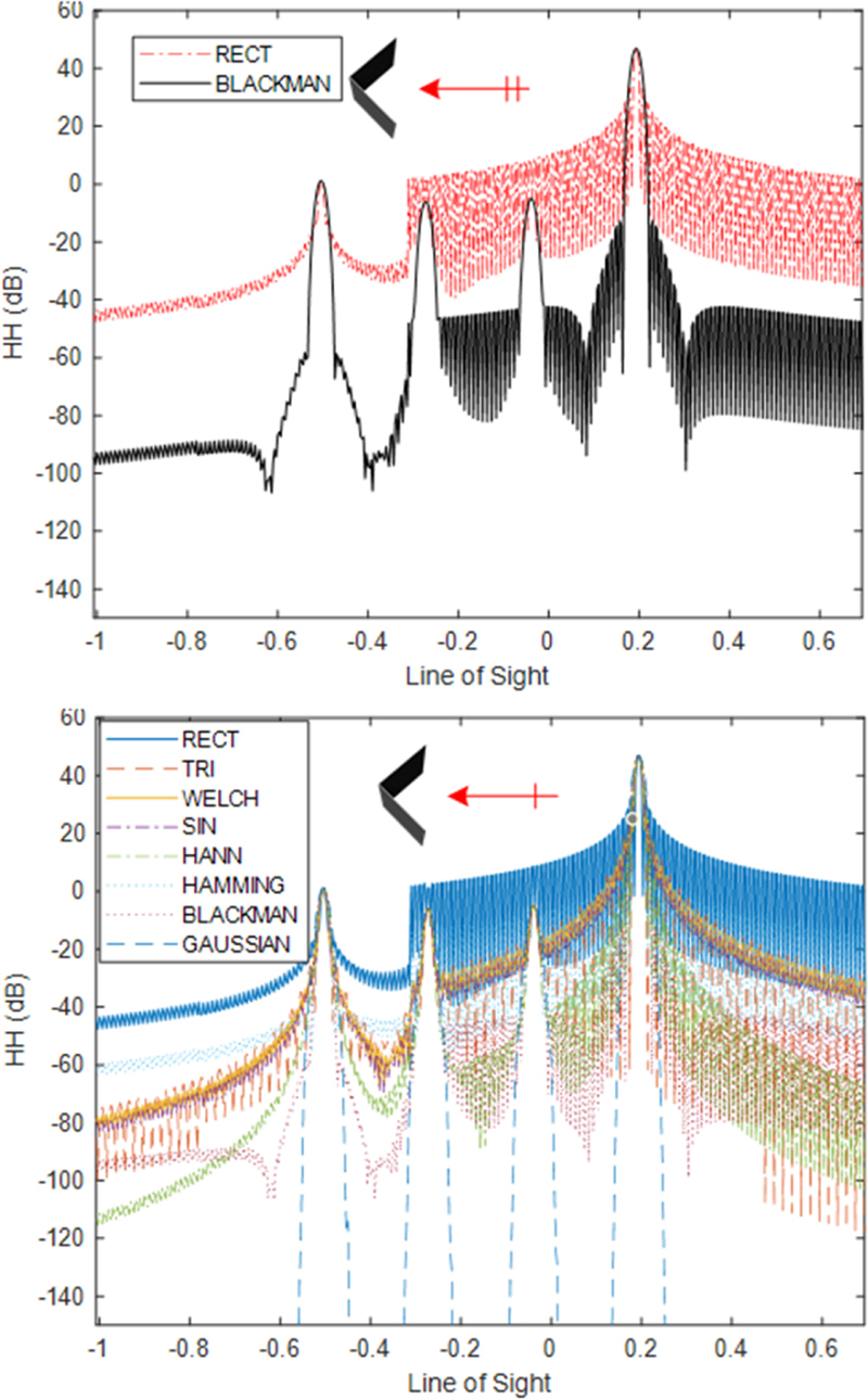
Figure 2: Comparison of dihedral angle one-dimensional distance images with rectangular and non-rectangular windows.
For Fig. 2, the radar resolution is 0.01m, the incident pitch angle is 90 degrees, the azimuth angle is 0 degrees, and the center frequency is 13.5GHz. As shown in Fig. 2, when a rectangular window is used, the secondary strong scatterers of the dihedral High Resolution Range Profile (HRRP) are almost drowned out by the sidelobes. After using a non-uniformly distributed window function, all the strong scatterers introduced by the dihedral due to multipath are clearly displayed because the sidelobes are suppressed. To clearly demonstrate the effect, the upper part of Fig. 2 only shows a comparison of the Blackman window and the Rectangular (RECT) window. As can be seen from the figure, the peak positions and peak amplitudes of the two completely overlap where there is no sidelobe obstruction. This validates the correctness of the weight coefficients and in the normalization formula. The main lobe of the Blackman window result shown in the figure is widened, which aligns with the characteristics of windowing in imaging. The lower part of Fig. 2 shows a comparison between all the window functions derived in this paper and the rectangular window. The correctness of the derivation of the weighting coefficients is validated through the degree of overlap of the peak positions and peak amplitudes, as well as the characteristics of the main lobe widening of each window function. Besides, the co-polarized RCS of this dihedral with the same excitation is 46.98 dBsm, which is equivalent to that of the main beam amplitude in HRRP. It also verifies the correctness of the normalized rapid imaging formulations.
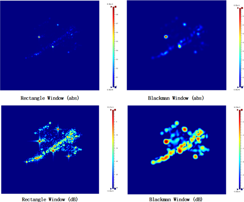
Figure 3: Comparison of two-dimensional imaging with rectangular and non-rectangular windows (using the Blackman window as an example).
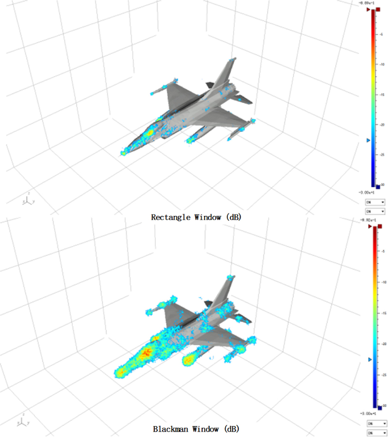
Figure 4: Application of three-dimensional windowed fast imaging.
Figures 3 and 4 give examples of two- and three-dimensional radar images, the radar resolutions are both 0.3 m, the incident pitch angles are 45 degrees, the azimuth angles are 45 degrees, and the center frequencies are 10 GHz. Figures 3 and 4 simultaneously provide the two-dimensional and three-dimensional radar imaging results characterized by absolute (abs) and decibel (dB) values. The dB representation can more clearly display the distribution of the secondary strong scatterers. As can be seen from the figures, the distribution of strong scatterers in the images obtained using non-uniform window functions (taking the Blackman window as an example) and the rectangular window (without windowing) are consistent. Due to the sidelobe suppression, the strong scatterers in non-rectangular window images are clearer, but the resolution is slightly reduced, i.e., the radius of the bright spot is slightly increased.
Owing to certain distinctive aspects of the high-frequency asymptotic algorithm [20, 21], the single-view one-dimensional distance image depicted in Fig. 2 demonstrates a slightly accelerated relative to a traditionally obtained sweep-frequency one-dimensional distance image. To be specific, the former technique procured the image in 0.013 s while the latter required 0.04 s for completion. However, the two-dimensional rapid single-view radar imaging methodology demonstrates markedly increased velocity compared to frequency-angle-scanning approaches. As evidenced by Fig. 3, generating ISAR imagery via RECT and Blackman windowing with the single-view method required approximately 6.7 s and 6.9 s, respectively. In stark contrast, the frequency-angle-scanning technique necessitated 1162.8 s to complete the equivalent imaging task.
Similarly, Fig. 4 provides a comparison before and after three-dimensional windowed imaging. Secondary hotspots become significant after non-rectangle windowed imaging.
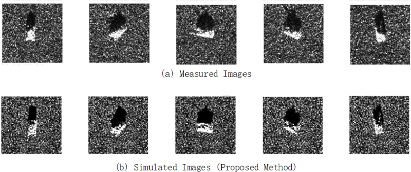
Figure 5: Two-dimensional imaging comparision between (a) simulated and (b) measured images.
To further validate the accuracy of two-dimensional imaging, we deployed the proposed methodology for target radar imaging using MSTAR measurement outcomes as a benchmark standard. Taking the T72 tank as an example, Fig. 5 shows that both target outlines, shadow outlines, and distributions of strong scatters correspond remarkably well, regardless of technique used. Consequently, the method advanced in this paper demonstrates aptitude for generating training datasets well-suited for target recognition algorithms.
Three-dimensional imaging has already become an information perception and utilization method in multiple input multiple output(MIMO) radar technology for autonomous driving [22, 7]. Drawing on perception training technology based on optical imaging, how to quickly obtain massive three-dimensional imaging data of terrestrial targets and environmental elements is one of the key technologies for the development of radar autonomous driving technology. The technology provided in this paper can help acquire three-dimensional imaging training data for autonomous drivingtechnology.
Figure 6 shows the three-dimensional imaging results of two types of road elements, vehicles and pedestrians, respectively, under 24 GHz (bandwidth 250 MHz) and 77 GHz (bandwidth 1 GHz), demonstrating different radar features from different perspectives. By taking them as typical scenes of panoramic streets and adding various typical elements such as vegetation, street lights, bicycles, etc. (as shown in Fig. 7), setting one of the vehicles with an autonomous driving MIMO radar, and setting the driving lane to constitute a typical autonomous driving scenario, the method proposed in this paper is used. The typical 3D imaging results under a working frequency of 77 GHz (bandwidth 1 GHz) are shown in Fig. 7. The left, middle, and right columns respectively represent the imaging results of beams irradiating to the left, middle, and right directions.
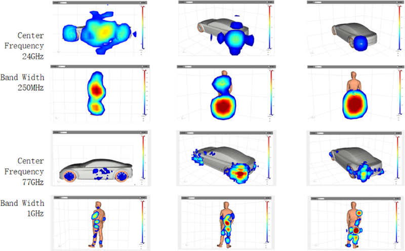
Figure 6: Three-dimensional imaging of typical vehicles and pedestrians at typical frequency bands.
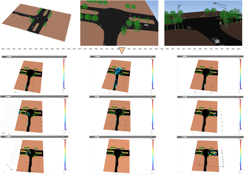
Figure 7: Scenes and their three-dimensional radar imaging during a vehicle’s journey.
As can be seen from the figure, the method proposed in this paper can provide three-dimensional imaging electromagnetic data under different radar working conditions for typical road elements and panoramic autonomous driving scenarios under different assumed conditions, providing massive training data for autonomous driving machine learning.
V. CONCLUSION
This paper derives and implements a windowed rapid single-view radar imaging technique, providing the analytical extension functions and normalized weighting values when applying typical window functions in single-view imaging. This technique retains the analytical form of rapid single-view radar imaging and, like traditional imaging techniques, can achieve window function filtering and sidelobe suppression effects. Moreover, its imaging efficiency is significantly higher than that of traditional frequency-angle-scanning imaging. It can provide a large number of simulation-based training samples for technologies such as target recognition, remote sensing, and autonomous driving.
ACKNOWLEDGMENT
This work was supported by the sub-project 61890544 of the National Natural Science Foundation of China project 61890540.
REFERENCES
[1] N. Daryasafar, R. A. Sadeghzadeh, and M. Naser-Moghadasi, “A technique for multitarget tracking in synthetic aperture radar spotlight imaging mode based on promoted PHD filtering approach,” Radio Sci., vol. 52, no. 2, pp. 248-258, Feb. 2017.
[2] H. Wang, Z. Chen, and S. Zheng, “Preliminary research of low-RCS moving target detection based on Ka-band video SAR,” IEEE Geosci. Remote Sens. Lett., vol. 14, no. 6, pp. 811-815, June 2017.
[3] K. D. Singh, “Automated spectral mapping and subpixel classification in the part of thar desert using EO-1 satellite hyperion data,” IEEE Geosci. Remote Sens. Lett., vol. 15, no. 9, pp. 1437-1440, Sep. 2018.
[4] C. Hu, L. Wang, Z. Li, and D. Zhu, “Inverse synthetic aperture radar imaging using a fully convolutional neural network,” IEEE Geoscience and Remote Sensing Letters, vol. 17, no. 7, pp. 1203-1207, Oct. 2019.
[5] G. Xu, B. Zhang, H. Yu, J. Chen, M. Xing, and W. Hong, “Sparse synthetic aperture radar imaging from compressed sensing and machine learning: Theories, applications, and trends,” IEEE Geoscience and Remote Sensing Magazine, vol. 10, no. 4, pp. 32-69, 2022.
[6] L. Tsang, J. A. Kong, and R. T. Shin, Theory of Microwave Remote Sensing, Wiley-Interscience, New York, 1985.
[7] M. Yang, P. López-Dekker, P. Dheenathayalan, F. Biljecki, M. Liao, and R. F. Hanssen, “Linking persistent scatterers to the built environment using ray tracing on urban models,” IEEE Trans. Geosci. Remote Sens., vol. 57, no. 8, pp. 5764-5776, Aug. 2019.
[8] S. K. Jeng, R. Bhalla, S. Lee, H. Ling, and D. J. Andersh, ‘‘A time-domain SBR technique for range-profile computation,” Electromagnetics Lab. Tech. Rep., Univ. of Illinois, Sep. 1993.
[9] R. Bhalla and H. Ling, “A fast algorithm for signature prediction and image formation using the shooting and bouncing ray technique,” IEEE Trans. Antennas Propag., vol. 43, no. 7, pp. 727-731, July 1995.
[10] R. Bhalla and H. Ling, “Image domain ray tube integration formula for the shooting and bouncing ray technique,” Radio Sci., vol. 30, no. 5, pp. 1435-1446, Sep. 1995.
[11] O. Kechagias-Stamatis and N. Aouf, “Automatic target recognition on synthetic aperture radar imagery: A survey,” IEEE Aerosp. Electron. Syst. Mag., vol. 36, no. 3, pp. 56-81, Mar. 2021.
[12] J. H. Cho and C. G. Park, “Multiple feature aggregation using convolutional neural networks for SAR image-based automatic target recognition,” IEEE Geosci. Remote Sens. Lett., vol. 15, no. 12, pp. 1882-1886, Dec. 2018.
[13] Y. Sun, L. Du, Y. Wang, Y. Wang, and J. Hu, “SAR automatic target recognition based on dictionary learning and joint dynamic sparse representation,” IEEE Geosci. Remote Sens. Lett., vol. 13, no. 12, pp. 1777-1781, Dec. 2016.
[14] X. Dai, X. Wu, B. Wang, and L. Zhang, “Semisupervised scene classification for remote sensing images: A method based on convolutional neural networks and ensemble learning,” IEEE Geosci. Remote Sens. Lett., vol. 16, no. 6, pp. 869-873, June 2019.
[15] H. Stankwitz, R. Dallaire, and J. Fienup, “Nonlinear apodization for sidelobe control in SAR imagery,” IEEE Trans. Aerosp. Electron. Syst., vol. 31, no. 1, pp. 267-279, Jan. 1995.
[16] F. Harris, “On the use of windows for harmonic analysis with the discrete Fourier transform,” Proc. IEEE, vol. 66, no. 1, pp. 51-83, Jan. 1978.
[17] N. Gong and X. Xu, “GRECO based fast prediction of 3D radar images for complex targets,” 2017 Sensor Signal Processing for Defence Conference, pp. 1-5, London, UK, Dec. 2017.
[18] X. Xu, “How to understand high resolution radar images and the pixel values of targets,” Chinese Journal of Radio Science, vol. 34, no. 1, pp. 33-44, Feb. 2019.
[19] J. M. Jin, The Finite Element Method in Electromagnetics, Wiley, New York, 2014.
[20] K. Ren and R. J. Burkholder, “A uniform diffraction tomographic imaging algorithm for near-field microwave scanning through stratified media,” IEEE Trans. Antennas Propag., vol. 64, no. 12, pp. 5198-5207, Dec. 2016.
[21] Y. Li, J. Zhang, J. Niu, Y. Zhou, and L. Wang, “Computational implementation and asymptotic statistical performance analysis of range frequency autocorrelation function for radar high-speed target detection,” IEEE Trans. Comput. Imaging, vol. 6, pp. 1297-1308, Aug. 2020.
[22] R. Bhalla, L. Lin, and D. Andersh, “A fast algorithm for 3D SAR simulation of target and terrain using Xpatch,” IEEE International Radar Conference, pp. 377-382, Arlington, VA, USA, May 2005.
BIOGRAPHIES

Wen Ming Yu was born in Zhuji, Zhejiang, China, in 1980. He received the B.Sc. and Ph.D. degrees from the Nanjing University of Science and Technology, Nanjing, China, in 2002 and 2007, respectively. He currently serves as a Lecturer at the School of Information Science and Engineering, Southeast University. His research interest is computational electromagnetics.

Yi Ting Yang (1992-) received the B.Sc. and M.Sc. degrees in communication engineering from the School of Electrical Engineering and Optical Technique, Nanjing University of Science and Technology, Nanjing, China, in 2013 and 2016, respectively. She is currently pursuing the Ph.D. degree in State Key Laboratory of Millimeter Waves, Southeast University, Nanjing. Her research interests include the areas of computational electromagnetics and absorbing material design.

Xiao Fei Lu was born in 1981. He received the B.S. and M.S. degrees from the Harbin Institute of Technology (HIT), Harbin, China, in 2002 and 2004, respectively, both in electronic engineering, and the Ph.D. degree in control theory and control engineering from Tsinghua University, Beijing, China, in 2012. He is currently an Engineer with Jiu Quan Satellite Launch Center. His main research interests include target recognition, radar signal processing, and their practical application. He has authored or coauthored more than 20 papers.

Chao Yang received the B.S. degree in applied physics from Xidian University, Xi’an, China, in 2014, and the Ph.D. degree in electronic science and technology from Zhejiang University, Hangzhou, China, in 2019. He is currently an assistant research fellow with Northwest Institute of Nuclear Technology, Xi’an, China. His research interests include computational electromagnetic, intense electromagnetic pulse environment, and electromagnetic scattering.

Zai Gao Chen was born in China in 1983. He received the B.S. degree in physical electronics from the University of Electronic Science and Technology of China, in 2005, and the M.S. degree in electromagnetic theory and microwave techniques from the Northwest Institute of Nuclear Technology (NINT), Xi’an, China, in 2008, and the Ph.D. degree in physical electronics from Xi’an Jiaotong University, Xi’an. He is currently working with NINT as an Associate Professor. His research interests mainly concentrate on numerical electromagnetic methods and plasma physics.

Tie Jun Cui (M’98-SM’00-F’15) received the B.Sc., M.Sc., and Ph.D. degrees in electrical engineering from Xidian University, Xi’an, China, in 1987, 1990, and 1993, respectively. He became an associate professor there in 1993, then worked in Germany at the University of Karlsruhe until 1997. After that, he joined the University of Illinois at Urbana-Champaign as a postdoc and research scientist. Since 2001, he has been a distinguished professor at Southeast University in China, where he now serves as the main professor and director of a key laboratory in millimeter waves, as well as founding an institute on electromagnetic space.
Dr. Cui’s research interests include metamaterials and computational electromagnetics. He proposed the concepts of digital coding and programmable metamaterials, and realized their first prototypes, based on which he founded the new direction of information metamaterials, bridging the physical world and digital world. He has written books on the subject, published over 600 journal articles, and holds more than 150 patents. His work has been widely reported by Nature News, MIT Technology Review, Scientific American, Discover, New Scientists, etc.
Dr. Cui is the Academician of Chinese Academy of Science, and IEEE Fellow. He has held editorial roles for several scientific journals and has delivered over 100 keynote speeches. In 2019-2021, he was ranked in the top 1% for the highly cited papers in the field of Physics by Clarivate Web of Science (Highly Cited Researcher).
ACES JOURNAL, Vol. 39, No. 1, 1–8
doi: 10.13052/2024.ACES.J.390101
© 2024 River Publishers