A Miniaturized Pattern-reconfigurable Antenna for Broadband VHF and UHF Communications
Haifan Li, Tingshuang Zheng, Yong Mao, and Yongjin Zhou
1Shanghai Collaborative Innovation Center of Intelligent Sensing Chip Technology
Key Laboratory of Specialty Fiber Optics and Optical Access Networks, Shanghai University,
Shanghai, 200444, China
leonlhf@shu.edu.cn, zts2023hf@163.com
2Wuhan Marine Communication Institute
Wuhan 430205, China
19989629966m@sina.cn
3Shaanxi Key Laboratory of Artificially-Structured Functional Materials and Devices
Air Force Engineering University, Xi’an 710051, China
yjzhou@shu.edu.cn
Submitted On: October 31, 2023; Accepted On: October 15, 2024
ABSTRACT
In this paper, a miniaturized and broadband patter-reconfigurable antenna working at very high frequency (VHF) and ultra-high frequency (UHF) band is proposed. A dipole antenna element with a compact size, stable horizontal gain, a wide bandwidth, and an omnidirectional pattern is introduced firstly, which operates from 116 MHz to 505 MHz with a relative bandwidth of 108.55% and a size of 0.11 0.33. An antenna array is constructed by combining four elements in a rotationally symmetrical manner. When one element is excited and other ports are terminated by matched loads, switchable directional beams are achieved. A 10:1 scaled model of the proposed antenna is fabricated and tested. Measured results show that the antenna element operates from 1.48 GHz to 4.86 GHz (a relative bandwidth of 106.62%) with a gain above -2 dBi. The proposed antenna array can achieve directional beams with a high front to back ratio (FBR) with gain value of 3-4 dBi within 2-4 GHz.
Index Terms: Broadband antennas, dipole antennas, pattern-reconfigurable antennas, VHF/UHF antennas.
I. INTRODUCTION
In modern tactical secure communication systems, spread spectrum and frequency hopping technology is frequently employed to enhance the anti-interference and confidentiality of aircraft and ship communication [1]. Numerous very high frequency (VHF) and ultra-high frequency (UHF) broadband omnidirectional antenna have been proposed over the decades [2–5]. To increase the bandwidth of VHF/UHF antenna, a biconical structure and thick dipole is utilized in [2], a dual-parasitic sleeve structure is applied to improve the impedance further. This design provides a working band that covers a range from 120 to 550 MHz (128%). A dual-sleeve wideband monopole antenna with loaded plasma cylinders is proposed for shipborne systems in VHF range in [3]. It achieves the VSWR 2 bandwidth of more than 107%. However, it is worth noticing that the prototypes of these antennas tend to be large in size and challenging to manufacture. Reference [4] designs a super broadband dipole antenna with a passive matching network. By loading lumped elements on the antenna body and using the genetic algorithm optimization, it can operate over 30-1200 MHz with VSWR 3 and broadside gain -10 dBi. However, the gain is too low to meet the requirements of practical applications.
On the other hand, pattern reconfigurable antenna and multibeam antennas are highly desired in military applications to enhance the capability of wireless communication systems. These technologies contribute to increase spectral efficiency, extend communication range, and improve security and anti-interference. In [6], a wideband multibeam circular array antenna for VHF/UHF directional networks applications is designed by introducing directional antenna element. The problem is that the finite ground plane causes a titled-up radiation pattern from the azimuth plane. Electrically steerable passive array radiators (ESPAR) are used to achieve a directional and steerable radiation pattern on the antenna horizontal plane [7–9]. Nevertheless, these antenna dimensions are characterized by large and complex dimensions and the controlling circuits loaded on the parasitic elements affect the quality of antenna radiation patterns.
Active frequency selective surfaces (AFSSs) attract significant attention in pattern reconfigurable antenna design [10–12]. These antennas can manipulate radiation direction and beamwidth by changing the PIN diodes or varactors on the AFSS. However, due to the limitation bandwidth of the FSS units, the pattern reconfigurable antennas based on AFSS could only dynamically switch the beams in one or a few operating bands, typically resulting in a larger volume.
This article presents a miniaturized and broadband pattern-reconfigurable VHF/UHF antenna that features four directional beams with high front to back ratio (FBR) in the horizontal plane. Employing a circular array configuration eliminates the need for placing directors or reflectors around the antenna at a distance of /4. This approach results in a more compact size and broader operating bandwidth. A 10:1 scaled model prototype is fabricated and tested to validate our simulation results. This article is organized as follows. In section II, the antenna element design and performance analysis are discussed in detail. In section III, an antenna array with directional beams is studied and the simulated and measured results are shown. Section IV is the conclusion of the entire paper.
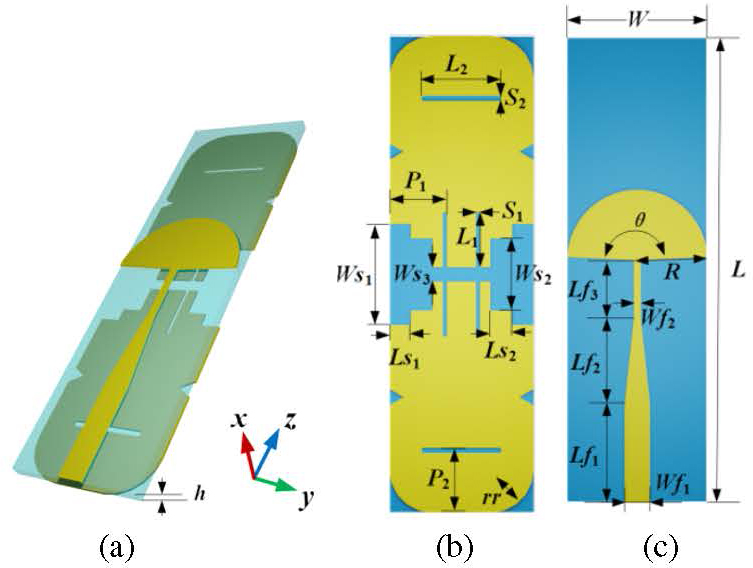
Figure 1: Configuration of the dipole antenna element: (a) 3D view, (b) top view, and (c) bottom view.
II. ANTENNA ELEMENT DESIGN AND PERFORMANCE ANALYSIS
A. Geometry of dipole antenna element
The configuration of the dipole antenna element is depicted in Fig. 1. It is printed on a FR4 substrate with a relative dielectric constant of 4.4, a loss tangent of 0.02 and a dimension of L W h. The antenna is fed at the bottom edge through a 50 SMA connector. The microstrip feeding structure comprises microstrip lines of different widths and a sector open-ended branch, which functions as a broadband unbalance-to-balance transition [13]. The microstrip line directly connected to the inner conductor of the SMA has a width of W and a length of L. After feeding through a trapezoidal patch with a length of L, W is transformed into a width of W, and then it is connected to a sector open-ended branch with a radius of R and an angle of .
The upper trimmed rectangle patches serve as radiating elements. The rectangle patch with an area of L W is divided into two parts by three stepped slots that traverse it. Each part features two vertical slots (L S) located next to the stepped slots and a horizontal slot (L S), which improves the impedance matching of the antenna. Other specific dimensions have been marked in Fig. 1 in detail.
With trimmed rectangle patches and microstrip feeding structure, the antenna element is significantly reduced, which has an electric size of 0.11 0.33( corresponding to the lowest frequency), and the bandwidth is expanded. Detailed dimension parameters of the VHF/UHF antenna element can be found in Table 1.
Table 1: Dimension parameters of the VHF/UHF dipole antenna element (unit: mm)
| Parameter | Value | Parameter | Value |
|---|---|---|---|
| L | 660 | W | 160 |
| W | 220 | L | 30 |
| W | 3.76 | W | 90 |
| L | 132 | L | 3 |
| W | 1 | W | 12 |
| L | 120 | L | 97 |
| L | 80 | S | 5.5 |
| R | 110 | L | 80 |
| 175 | S | 4 | |
| P | 85 | rr | 90 |
| P | 100 | h | 2 |
B. Antenna element performance and analysis
The proposed antenna element was simulated and optimized in CST STUDIO SUITE 2019 software. The antenna is fed by an ideal wave-port in the simulation. The fabricated VHF/UHF dipole antenna is shown in Fig. 2 (a). The simulated and measured |S| are illustrated in Fig. 2 (b). Simulated reflection coefficient curve shows that it operates from 149.73 MHz to 505.15 MHz (|S| -6 dB, 108.55%). The measured bandwidth covers from 116 MHz to 505 MHz (|S| -6 dB, 125.28%). The difference between the simulated and measured results is mainly due to the practical coaxial connector. In addition, the difference of the dielectric constant in simulation and fabrication will also cause a slight frequency shift. From Fig. 2 (b), it can be seen that the modified simulation results (blue line) agree better with the measured ones, where the coaxial connector was modeled in simulation and the relative dielectric constant of the substrate was changed to 4.8.
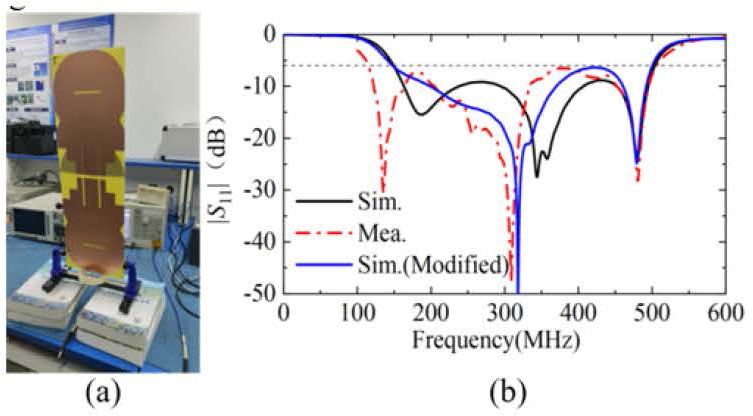
Figure 2: The fabricated VHF/UHF dipole antenna: (a) 3-D view and (b) simulated and measured |S|.
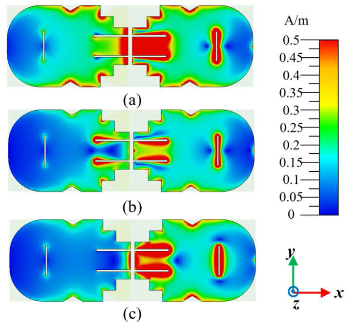
Figure 3: Surface current distributions of the VHF/UHF antenna at (a) 187 MHz, (b) 358 MHz, and (c) 480 MHz.
The basic working principle of the broadband antenna is to excite multiple resonant modes which are close to each other. To demonstrate the basic working principle of the antenna, surface current distributions at different resonant frequencies are presented in Fig. 3. It can be seen that current distribution primarily concentrates on the edge of the patches at 187 MHz and the effective current path is the longest, which determines the lowest resonance. At 358 MHz, current distribution concentrates on the four slots, while it concentrates on the two slots at 480 MHz. It can be seen that as the operating frequency increases, the effective current path becomes shorter.
Due to the limitation of the anechoic chamber, where the minimum frequency is 1 GHz, a 10:1 scaled model was fabricated and tested, as shown in Fig. 4 (a). The 10:1 scaled model exhibits a slight variation in structure with the VHF/UHF antenna, primarily due to limitations imposed by the dielectric substrate and the cost. Simulated and measured return loss and gain of the 10:1 scaled antenna element were conducted in an anechoic chamber as plotted inFigs. 4 (a) and (b).
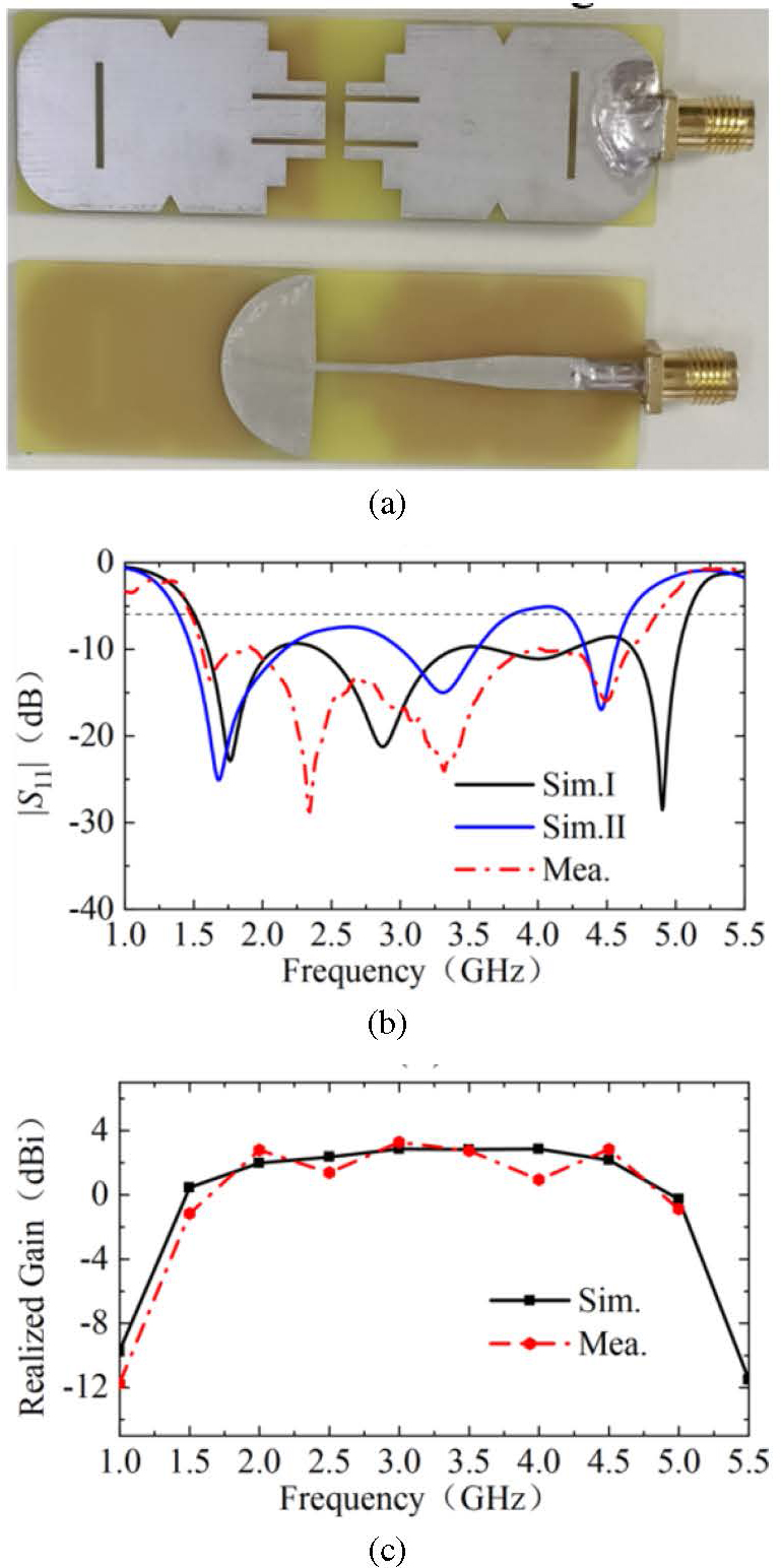
Figure 4: Fabricated 10:1 scaled antenna element and its experiment results: (a) top view and bottom view, (b) simulated and measured |S|, and (c) simulated and measured gain.
The simulated bandwidth covers from 1.51 GHz to 5.08 GHz (|S| -6 dB, 108.43%), as shown by the black solid line Sim.I. The measured bandwidth (red dashed line) covers from 1.48 GHz to 4.86 GHz (106.62%). The measured bandwidth is in good agreement with the simulated one, except those resonant frequencies shift towards lower frequencies. We changed the dielectric constant of FR4 from 4.4 to 4.8, and the new simulation result is denoted as Sim.II in Fig. 4 (b). It can be seen that the resonant frequencies of Sim.II agree better with the measured resonant frequencies. In addition, coaxial connectors and soldering may influence the resonance frequency shift.
Realized radiation patterns in the E-plane and H-plane ( 90 plane) at 1.5, 2.5, 3.5, and 4.5 GHz are depicted in Fig. 5. It is evident that the out-of-roundness becomes worse with the increasing of working frequency, although the antenna’s omnidirectional characteristics in the broadband spectrum remain observable. The asymmetry of the E-plane can be attributed to the influence of the substrate and feeding structure.
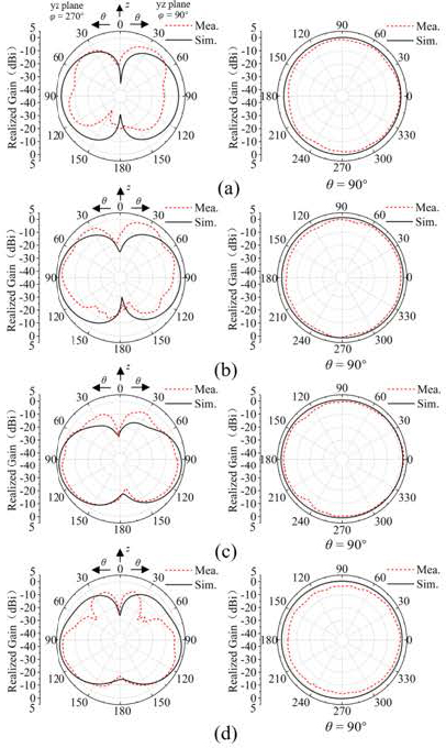
Figure 5: Measured and simulated radiation patterns of the proposed 10:1 scaled model dipole antenna element: (a) 1.5 GHz, (b) 2.5 GHz, (c) 3.5 GHz, and (d) 4.5 GHz.
III. ANTENNA ARRAY AND EXPERIMENTAL VALIDATION
A. Antenna array structure and principle
Based on the proposed dipole antenna element, an antenna array is constructed, where four elements are arranged in a circular array configuration with a radius r 25 mm, as shown in Fig. 6 (a). Circular array antennas have found extensive applications in systems such as radio direction finding, radar navigation, and underground detection [14–17]. Their advantages lie in the ability to generate both omnidirectional patterns and directional patterns with the main lobe pointing towards the normal direction of the array. The antenna structure of a uniform circular array makes its azimuth scanning angle higher than that of a linear array or rectanglearray.
The overall antenna array fits in a volume of 53.2 53.2 66 mm. When Ant.I is excited and the other three antennas are terminated with 50 matched loads, a directional pattern is realized, as plotted inFig. 6 (b).
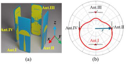
Figure 6: Geometry of the proposed antenna array and reconfigurations for directional pattern (r 50 mm): (a) 3-D view and (b) directional pattern when Ant.I is fed.
When the other three antennas are excited in the same way, three directional beams can be achieved. These four directional beams are at an interval of 90 in the H-plane ( 90 plane). Since the bandwidth of the antenna element is wide, pattern reconfigurability can also be realized over a wide frequency range The impact of the mutual coupling is investigated in the nextsection.
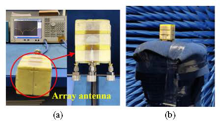
Figure 7: Photograph of the fabricated 10:1 scaled antenna array and its experimental scenario: (a) measurement of S parameters and (b) measurement of the radiation patterns.
B. Results and discussion
The experimental setup of the proposed antenna array is shown in Fig. 7. Simulated and measured S parameters are plotted in Fig. 8. The isolation between the elements is better than 12.5 dB, and the |S| is less than -6 dB over the frequency range 1.66-4.78 GHz. In a practical testing environment, S and S are nearly identical due to structure symmetry. When using the same operation to feed the other three ports separately, three directional beams are also obtained.
Radiation characteristics of the antenna array were evaluated in an anechoic chamber similarly. The radiation patterns at different frequencies (2, 3, and 4 GHz), when one element is fed and other ports are terminated by matched loads, are shown in Fig. 9. The maximum horizontal gain in 2 GHz, 3 GHz, and 4 GHz are 2.5 dBi, 4.9 dBi, and 3.1 dBi, corresponding to the FBR with 12.4 dB, 9.8 dB, and 13.1 dB, respectively. All results show directional beams in the azimuth plane with relatively high FBR.
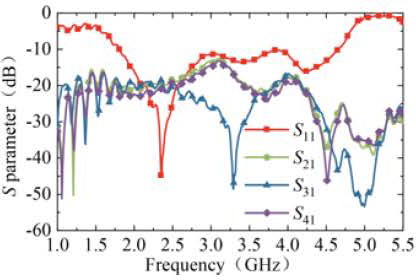
Figure 8: Measured S parameter of the antenna array.
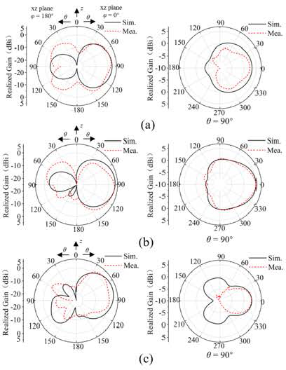
Figure 9: Simulated and measured radiation patterns of the proposed 10:1 scaled model antenna array: (a) 2 GHz, (b) 3 GHz, and (c) 4 GHz.
The small deviation between the simulated measured results may be caused by the difference between the simplified wave-port model in simulation and the actual dimensions of coaxial cables and matching loads. In addition, the small size of the antenna results in a relatively low gain in lower frequency measurement. The welding and fine features near the feed ports also introduce adverse effects.
IV. CONCLUSION
This paper proposed a miniaturized and broadband pattern-reconfigurable VHF/UHF antenna which features four directional beams with high FBR in the horizontal plane. A dipole VHF/UHF antenna element characterized by its compact size, stable horizontal gain, wide bandwidth (116-505 MHz, a relative bandwidth of 108.55%), and omnidirectional pattern is designed firstly. Then, a 10:1 scaled model is fabricated and tested. Measurement results show that the impedance bandwidth of antenna element covers from 1.48 to 4.86 GHz (a relative bandwidth of 106.62%) with omnidirectional characteristics. An antenna array with directional beams is designed and tested afterwards. The overall 10:1 scaled antenna array measures 53.2 53.2 66 mm (0.27 0.27 0.33). Measured results reveal directional beams can be achieved in the azimuth plane with a relatively high FBR within 2-4 GHz. More flexible beams can be generated by exciting more elements or changing the feeding phase of each port in the future works.
ACKNOWLEDGMENT
This work is supported by the National Natural Science Foundation of China under Grant No. 61971469, the Science and Technology Commission Shanghai Municipality under Grant No. 18ZR1413500, the Open Project Program of the State Key Laboratory of Millimeter Waves under Grant No. K202109 and Fundamental Research Funds of Shaanxi Key Laboratory of Artificially-Structured Functional Materials and Devices (AFMD-KFJJ-21105).
REFERENCES
[1] S. R. Kingston, H. Ellis, M. U. Saleh, E. J. Benoit, A. Edun, C. M. Furse, M. A. Scarpulla, and J. B. Harley, “Spread spectrum time domain reflectometry and steepest descent inversion spread spectrum time domain reflectometry and steepest descent inversion,” Applied Computational Electromagnetics Society (ACES) Journal. vol. 36, no. 2, pp. 190-198, 2021.
[2] Y. Xia, Y. Li, and W. Xue, “A low profile miniaturization low frequency wideband antenna using passive lumped elements loading,” Applied Computational Electromagnetics Society (ACES) Journal, vol. 35, no. 1, pp. 31-37, 2020.
[3] C. Wang, B. Yuan, J. Mao, and W. Shi, “Dual-sleeve wideband monopole antenna for shipborne systems in VHF band,” Electron. Lett., vol. 54, no. 19, pp. 1102-1104, 2018.
[4] M. Bod, M. Ahmadi-Boroujeni, and K. Mohammadpour-Aghdam, “Design of a low-cost broadband loaded dipole antenna for VHF/UHF frequency range,” IET Microw. Antennas Propag., vol. 13, no. 12, pp. 1983-1988, 2019.
[5] C. Wang, B. Yuan, W. Shi, and J. Mao, “Low-profile broadband plasma antenna for naval communications in VHF and UHF bands,” IEEE Trans. Antennas Propag., vol. 68, no. 6, pp. 4271-4282, 2020.
[6] M. Mirmozafari, R. Ma, F. T. Dagefu, and N. Behdad, “A compact wideband multi-beam antenna for VHF/UHF directional networking applications,” IEEE Trans. Antennas Propag., vol. 70, no. 11, pp. 10113-10122, 2022.
[7] L. Batel, A. Clemente, and C. Delaveaud, “High-gain wideband and superdirective electronically-beam-switchable antenna for smart communication objects,” in 2022 16th European Conference on Antennas and Propagation (EuCAP), pp. 1-5,2022.
[8] L. Batel, A. Clemente, and C. Delaveaud, “Superdirective and compact electronically-beam-switchable antenna for smart communication objects,” in 2019 13th European Conference on Antennas and Propagation (EuCAP), pp. 1-4,2019.
[9] L. Xing, J. Zhu, Q. Xu, D. Yan, and Y. Zhao, “A circular beam-steering antenna with parasitic water reflectors,” IEEE Antennas and Wirel. Propag. Lett., vol. 18, no. 10, pp. 2140-2144,2019.
[10] J. Hou, Z. Chen, Z. Wang, D. Huang, and T. A. Denidni, “Beam-sweeping antenna with beamwidth reconfigurable response,” International Journal of RF and Microwave Computer-Aided Engineering, vol. 31, no. 12, pp. 1-9, 2021.
[11] J. Li, Q. Zeng, R. Liu, and T. A. Denidni, “A compact dual-band beam-sweeping antenna based on active frequency selective surfaces,” IEEE Trans. Antennas Propag., vol. 65, no. 4, pp. 1542-1549, 2017.
[12] B. Liang, B. Sanz-Izquierdo, E. A. Parker, and J. C. Batchelor, “Cylindrical slot FSS configuration for beam-switching applications,” IEEE Trans. Antennas Propag., vol. 63, no. 1, pp. 166-173,2015.
[13] J. P. Zhang, Y. S. Xu, and W. D. Wang, “Ultra-wideband microstrip-fed planar elliptical dipole antenna,” Electron. Lett., vol. 42, no. 3, pp. 144-145, 2006.
[14] H. Liu, Y. Liu, W. Zhang, and S. Gao, “An ultra-wideband horizontally polarized omnidirectional circular connected Vivaldi antenna array,” IEEE Trans. Antennas Propagat., vol. 65, no. 8, pp. 4351-4356, 2017.
[15] T. Li, F. S. Zhang, F. Zhang, Y. L. Yao, and L. Jiang, “Wideband and high-gain uniform circular array with calibration element for smart antenna application,” IEEE Antennas Wirel. Propag. Lett., vol. 15, pp. 230-233, 2016.
[16] P. Ioannides and C. A. Balanis, “Uniform circular and rectangular arrays for adaptive beamforming applications,” IEEE Antennas and Wirel. Propag. Lett., vol. 4, pp. 351-354, 2005.
[17] C. A. Balanis, Antenna Theory: Analysis and Design, 4th ed. New York: Wiley, 2016.
BIOGRAPHIES

Haifan Li was born in Zhengzhou, Henan, China, in 2000. He is currently pursuing the master’s degree of Electromagnetic Field and Microwave Technology in Shanghai University, Shanghai 200444, China. His current research is focused on pattern reconfigurable antenna and time-varying metasurface.

Tingshuang Zheng was born in Henan, China, in 2000. She is currently pursuing the master’s degree of Electromagnetic Field and Microwave Technology in Shanghai University, Shanghai 200444, China. Her current research is focused on pattern reconfigurable antenna and antenna RCS reduction and metamaterials.

Yong Mao was born in Zigong, Sichuan, China, in 1981. His current research interests focus on marine antenna. He received the B.S. degree in communication engineering University of Electronic Science and Technology of China, Chengdu, China, in 2004, and M.S. degree in telecommunication engineering Huazhong University of Science and Technology, Wuhan, China, in 2009, respectively. From 2004, he was a research fellow with Wuhan Marine Communication Institute, Wuhan 430205, China. He has authored and coauthored over 20 papers in peer-reviewed journals and conference proceedings. He is Member of Hubei Provincial Institute of Communications, and Member of Chinese Institute of Electronics.

Yongjin Zhou received the B.S. degree in communication engineering from Shandong University, Jinan, China, in 2006, and Ph.D. degree in electromagnetic field and microwave technology from Southeast University, Nanjing, China, in 2011, respectively. From 2009 to 2010, he was a visiting scholar of University of Houston. From 2011 to 2012, he was a software engineer with EEBU of Marvell Technology (Shanghai) Ltd. From 2012 to 2015, he was an Assistant Professor with School of Communication & Information Engineering, Shanghai University, Shanghai, China. From 2015, he was an Associate Professor with School of Communication & Information Engineering, Shanghai University, Shanghai, China. From 2020, he was a Professor with School of Communication & Information Engineering, Shanghai University, Shanghai, China. His current research interests include plasmonic metamaterials, millimeter wave and THz functional devices, wireless energy transmission, computational electromagnetism. He has served as Applied Computational Electromagnetics Society (ACES) Journal guest editor and is serving as a Youth Editorial Board Member Journal of Electronics & Information Technology. He is serving as a Reviewer for over 20 peer-reviewed journals, such as Nature Electronics, Photonic Research, Optics Letter, Optics Express, Appl. Phys. Express, IEEE Access, IEEE MTT, IEEE MWCL, etc. He has served as a session chair for several International Symposiums.
ACES JOURNAL, Vol. 39, No. 8, 668–674
doi: 10.13052/2024.ACES.J.390801
© 2024 River Publishers