Ultra-wideband Planar Magic-T using Interlayer Coupling 3 dB Directional Coupler and Branch-loaded Phase Shifter
Yanzhen Shi, Dapeng Chu, and Yongjin Zhou
1Shanghai Collaborative Innovation Center of Intelligent Sensing Chip Technology
School of Communication and Information Engineering, Shanghai University, Shanghai 200444, China
yanzhen_shi@163.com, chudapeng1997@163.com
2State Key Laboratory of Millimeter Waves, School of Information Science and Engineering
Southeast University, Nanjing 210096, China
3Shaanxi Key Laboratory of Artificially-Structured Functional Materials and Devices
Air Force Engineering University, Xi’an 710051, China
yjzhou@shu.edu.cn
Submitted On: October 31, 2023; Accepted On: June 26, 2024
ABSTRACT
In this paper, we propose an ultra-wideband magic-T operating in the frequency band from 1.2 to 4 GHz with a relative bandwidth of 108%, which is based on an interlayer coupling 3 dB directional coupler and a branch-loaded 90 phase shifter. Compared to traditional magic-T structures, it can operate within an ultra-wideband range and has the advantages of a simple structure and easy processing. Simulation and experimental results demonstrate excellent amplitude and phase stability. When the input is at the sum port, the phase error at each output port is less than 2.8. For the difference port input, the phase error at each output port is less than 7.6. Furthermore, the overall amplitude imbalance is less than 2.1 dB, the transmission coefficient is below 7.4 dB, and the isolation is greater than 11 dB. It can be used in ultra-wideband phased array systems to generate sum-and-difference beams for direction finding.
Index Terms: Coupler, magic-T, phase shifter; ultra-wideband.
I. INTRODUCTION
In recent years, military systems have been operating in a very wide frequency range with bandwidth requirements extending from L-band to Ka-band. Magic-T networks are widely used in phased-array radar systems as sum-and-difference networks to generate sum-and-difference signals for target direction detection, enabling radar target detection tasks. As one of the core components of radar, the magic-T network is facing higher demands. It needs to have the widest possible operating bandwidth to enable the radar to detect targets over a broad frequency range. The demand for ultra-wideband magic-T network systems (the relative bandwidth is larger than 100%) is becoming increasingly urgent.
In recent years, extensive research has been conducted on the magic-T network. However, the conventional magic-T has a narrow bandwidth, such as the coplanar magic-T based on substrate integrated waveguide (SIW) in [1], which has a bandwidth of 5.8%. References [2–4] have worked on increasing the bandwidth of SIW-based magic-T networks, achieving bandwidths ranging from 23.2% to 78.7%. A new ridge-shaped SIW is proposed in [4] to achieve 78.7% (6.4-14.7 GHz) relative bandwidth by a stepped band line optimized by genetic algorithm (GA). Despite the high performance of waveguide SIW-based magic-T, its structure is complex, more difficult to process, and more costly. To enhance the operational bandwidth, certain studies have suggested magic-T networks based on microstrip or slot lines. For example, a new broadband magic-T based on slot line T-junctions and microstrip line-slot line conversion is proposed in [5] with a bandwidth of 40%. In addition, a broadband planar magic-T using microstrip line-slot line conversion with a relative bandwidth of 70% is presented in [6]. However, these methods still cannot satisfy the ultra-wideband requirements of the system. Conventional 3 dB couplers based on microstrip or slotted lines combined with 90 phase shifters can also provide magic-T functionality [7–10]. Reference [8] achieves a magic-T with a relative bandwidth of 40%. Reference [9] achieves a relative bandwidth of 89% (5-13 GHz) by narrow-edge coupling and wide-edge coupling. Most of the above studies have focused on X-band and C-band; there are relatively few studies on magic-T covering L-band.
In view of the wide application of L/S-band in communication and satellite, we propose an ultra-wideband magic-T network that covers the L/S bands. The network is based on a 3 dB coupler and a 90 phase shifter, operating in the 1.2-4 GHz range, with a relative bandwidth of up to 108%. The transmission coefficient is less than 7.4 dB, and the phase imbalance is less than 2.8, with an amplitude imbalance of less than 2.1 dB.
II. MAGIC-T DESIGN
The ultra-wideband magic-T consists of a cascade of a 3 dB directional coupler and a 90 phase shifter, which can be applied as a sum-and-difference network in phased-array systems, and its network topology is shown in Fig. 1.
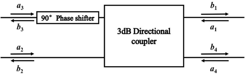
Figure 1: Schematic diagram of the proposed magic-T.
Assume that represents the normalized voltage of the incident wave and represents the normalized voltage of the incident wave. For the orthogonal hybrid network, the phase of the coupled output port 3 lags behind that of the straight-through port 2 by 90 when the electromagnetic wave is input from port 1, so the scattering matrix S of the 3 dB directional coupler is:
| (1) |
The coupled output port 3 in turn passes through a 90 phase shifter, so the normalized value of the reflected wave voltage of the cascade network can be expressed as:
| (2) |
From the above equation, we have:
| (3) | |
The above theoretical analysis shows that port 1 of this cascade network can be used as the sum port of the sum-difference network, and port 4 can be used as the difference port.
A. Interlayer coupling ultra-broadband directional coupler
The form of the 3 dB directional coupler in the proposed magic-T network uses a coupled-line directional coupler with its coupled port and straight-through port output signal power being equal, and a phase difference of 90. For the planar coupled line directional coupler, even if the spacing between the coupled lines is close to the practical processing precision limit, it is still challenging to achieve the 3 dB coupling requirement. Scholars have also tried various methods to increase the electromagnetic coupling between planar microstrip lines, but these techniques have significantly increased the processing difficulty. To achieve an easily manufacturable and strongly coupled directional coupler based on planar microstrip lines, a multilayer microstrip structure based on interlayer coupling [11] was proposed, and Figs. 2 (a) and (b) show the top and side views of this structure, respectively. The structure includes two layers of dielectric substrate with a common metal ground in the middle layer. The microstrip transmission lines are located on the surfaces of the two layers of the dielectric substrate and coupled broadside through the coupling holes in the hollow part of the metal ground, and the size of the coupling microstrip lines and coupling holes determines the degree of coupling. By reasonably adjusting the size of the coupling area, the structure can achieve a coupling degree of 3 dB or more.
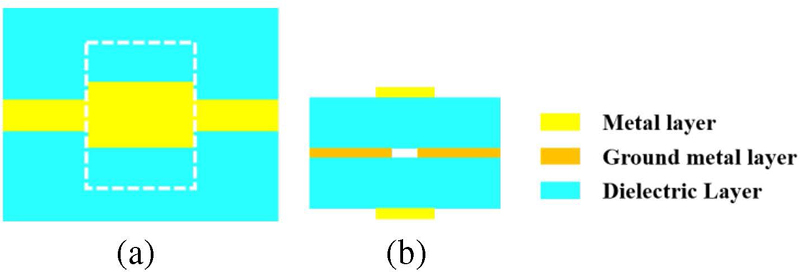
Figure 2: Multi-layer coupling line structure: (a) top view and (b) side view.
The relationship between odd mode and even mode impedances and slot width, as well as microstrip line width, can be obtained as follows [11, 14]:
| (4) | |
where represents the complete elliptic integral of the first kind, , and represent the odd mode impedance and even mode impedance, respectively, h is the thickness of the dielectric layer, is the width of the coupled microstrip lines on the top and bottom layers, and is the width of the slot on the middle ground layer.
Since the length of the coupled microstrip line is /4 (where is the wavelength corresponding to the center frequency), the single-section coupled-line coupler is limited in bandwidth [12], while the magic-T network in this design needs to meet the ultra-wideband requirements. To further expand the bandwidth and improve the phase balance, in this work, a three-section /4 length coupled-line coupler is designed using a multi-layer microstrip structure based on interlayer coupling. The structure consists of a weakly coupled section, a strongly coupled section, and another weakly coupled section, in that order. The schematic diagram of the three-section coupled-line coupler is shown in Fig. 3. The designed coupler is symmetrical, with the first and third sections of the coupled line having the same coupling coefficients, representing the weakly coupled parts, while the second section serves as the strongly coupled part.
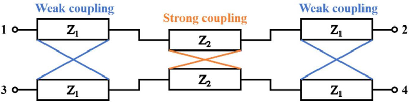
Figure 3: Prototype three-stage coupler.
By analyzing the even and odd modes of the coupled-line coupler and referring to R. Mongia’s design table [13], the characteristic impedances for each section of the 3 dB three-section coupled-line coupler can be obtained. The odd mode and even mode characteristic impedance of the first and third sections are , the odd mode and even mode characteristic impedance of the second section are , respectively. Using equations (5) and (6), we can calculate the coupling coefficients for each section. The coupling coefficients for the first and third sections of the coupled-line coupler are , resulting in coupling degrees of . Additionally, the second section exhibits a coupling coefficient of and a coupling degree of :
| (5) |
| (6) |
Once the substrate thickness and dielectric constant are determined, and given the odd mode and even mode characteristic impedances and coupling degrees for each section, the approximate dimensions of the coupling microstrip lines and coupling holes can be calculated using equation (4).
Figures 4 and 5 show the 3D schematic and top view of the three-section coupled-line coupler, respectively. The structure consists of three layers of metal and two layers of dielectric substrate, with the dielectric substrates all having a thickness of 1 mm made of FR4 material, having a relative dielectric constant of 4.4 and a loss tangent of 0.025. The microstrip transmission lines are located in the top and bottom layers of the structure. The metal ground is located in the middle layer with apertures for coupling holes. The overall structure is symmetrically distributed along the center of the metal ground plane, which is low cost and easy to process. When the signal is input, the output signal power at the coupled port and the straight-through port is equal and the phase difference is 90. The coupling strength of each /4 coupling line section is marked in Fig. 5, with the first and third sections representing weak coupling, and the intermediate second section indicating strong coupling. The microstrip lines in the weak coupling section are slotted to avoid the narrow microstrip lines from affecting the subsequent circuit design.
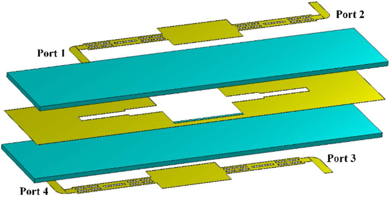
Figure 4: 3D schematic of the three-section coupled-line coupler.
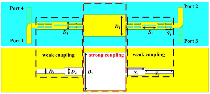
Figure 5: Top view of the three-section coupled-line coupler.
The optimal structural dimensions obtained by modeling and optimizing each parameter of the coupler in the electromagnetic simulation software CST are shown in Table 1.
Table 1: The optimized values of the coupler (unitmm)
| Parameter | Value | Parameter | Value |
|---|---|---|---|
| D | 2.98 | D | 14.80 |
| D | 8.46 | S | 2.50 |
| D | 1.78 | S | 5.00 |
| D | 2.98 | S | 7.50 |
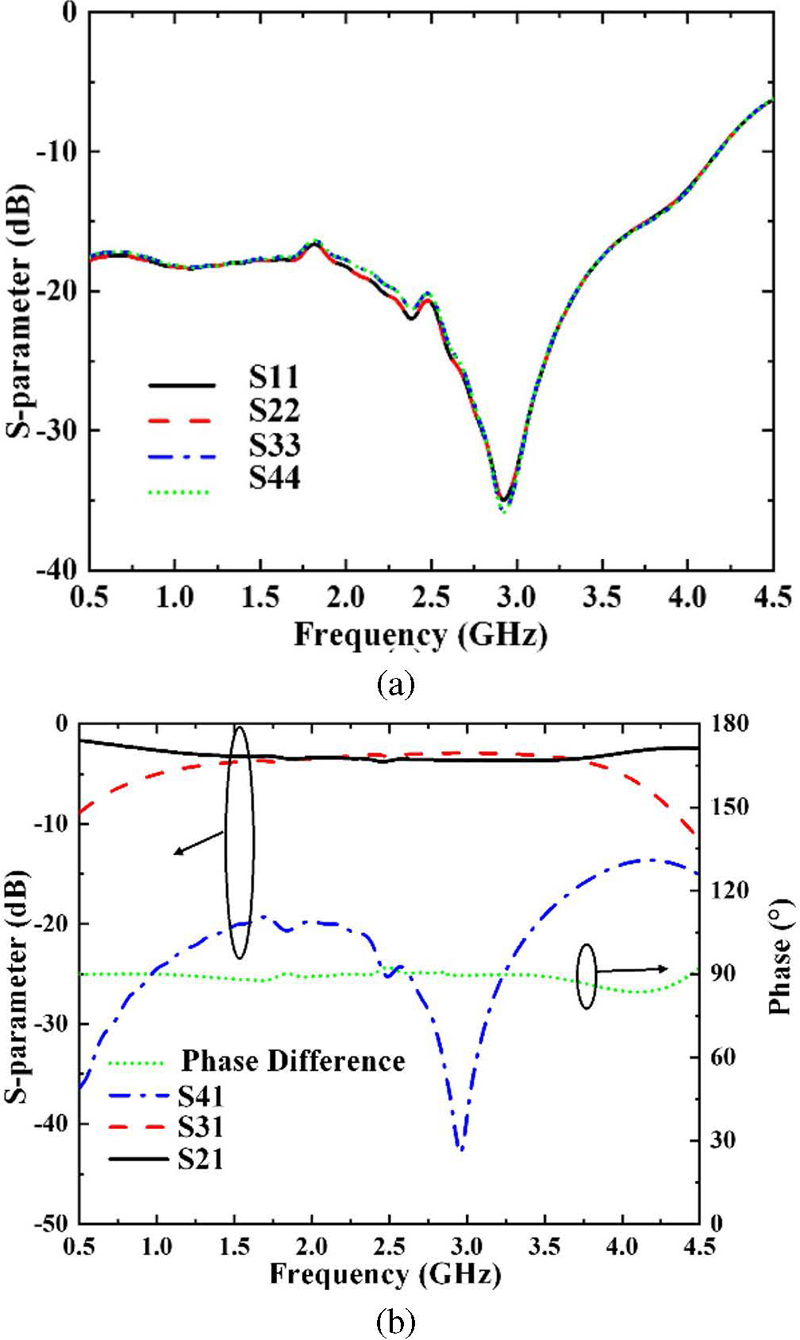
Figure 6: Simulation results of the couple: (a) reflection coefficient and (b) phase difference between coupled port and straight-through port, transmission coefficient and isolation.
The simulation results of the optimized coupler in CST are shown in Fig. 6. From the simulation results, it can be observed that within the operating frequency range of 1.2-4 GHz, the reflection coefficient of each port is less than 12 dB. The isolation refers to the extent to which the signal at one port influences other ports during propagation. For a four-port network, isolation can be calculated using the following formula: Isolation (dB)S (dB). Here, i and j denote two different ports of the network, and S represents the corresponding element in the S-parameter matrix. The isolation between ports 2 and 3, as well as between ports 1 and 4, defined as S41 or S23, exceeds 15 dB. The transmission coefficient of the straight-through port and the coupled port is approximately 3 dB, and the phase difference is around 90. The amplitude imbalance is less than 1.3 dB and the phase imbalance is less than 1.8. The coupler has good performance in all aspects and basically meets the index requirements of ultra-broadband magic-T network.
B. Branch loading type ultra-wideband phase shifter
The 90 phase shifter required in the magic-T network should also meet the ultra-wideband requirements, and the operating band of this phase shifter should be consistent with that of the 3 dB directional coupler and be structurally easy to cascade with the coupler. Compared with other types of phase shifters, the branch-loaded phase shifter can adjust the phase slope of the insertion phase shift by changing the impedance of the loaded branch [15], allowing it to achieve a constant phase shift value within a specific frequency band. This phase shifter can be realized using a single-layer microstrip structure, which simplifies the manufacturing process while ensuring stable performance. As a result, it is an excellent choice for constructing magic-T networks. The traditional branch-loaded phase shifter has a relatively narrow operating band, making it difficult to achieve a bandwidth of over three times the center frequency. To meet the bandwidth requirements of ultra-wideband magic-T networks, it’s necessary to extend the bandwidth of branch-loaded phase shifters. One approach for achieving this is by using multimode resonators, which can expand the phase shifter’s bandwidth to over three times the center frequency while maintaining a relatively simple structure.
According to the method in [16], considering both the amplitude and phase shift responses of the phase shifter, the characteristic impedances of the multimode resonator and the loaded branch can be determined once the reflection coefficient and phase shift deviation are established. Figure 7 shows the circuit schematic of a multimode resonator-based branch-loaded ultra-wideband phase shifter. The phase shifter consists of two branches, and the phase-shifting branch is composed of a multimode resonator with characteristic impedances Z and Z and two parallel short-circuiting branches with characteristic impedances Z. The length of each segment of the multimode resonator and the length of the shorting branch are both /2 (where is the wavelength corresponding to the center frequency). The reference branch is a uniform transmission line with a characteristic impedance of Z and a length of l, determined by the phase difference between the two branches. When the phase shift value is 90, the length is 2. According to microwave network theory, the S-parameters of the phase-shifted branch can be obtained by the transmission (ABCD) matrix, as follows:
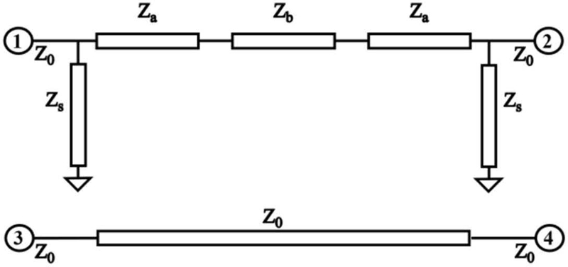
Figure 7: The circuit schematic diagram of a multimode resonator-based dendritic loading type ultra-wideband phase shifter.
The phase difference between the two branches, i.e. the phase shift value, can be expressed as:
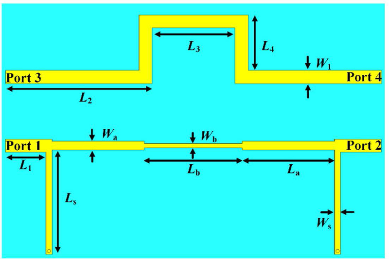
Figure 8: Simulation model of branch-loaded ultra-wideband phase shifter.
Given a reflection coefficient of 20 dB, a phase shift deviation of 5, and a port impedance of , the characteristic impedances of the multimode resonator in the 90 phase shifter are and , while the characteristic impedance of the loaded branch is . The phase shifter uses FR4 dielectric substrates with a thickness of 1 mm, similar to the coupler. It employs a single-layer microstrip structure for ease of cascading, with a center frequency of 2.6 GHz. The simulation model established in CST is shown in Fig. 8, and the specific structure dimensions obtained by fine-tuning the theoretical values are shown in Table 2.
Table 2: The optimized values of the phase shifter (unitmm)
| Parameter | Value |
|---|---|
| L | 2.97 |
| L | 8.46 |
| L | 1.77 |
| L | 2.97 |
| L | 13.69 |
| L | 14.53 |
| L | 15.50 |
| W | 1.94 |
| W | 1.27 |
| W | 0.63 |
| W | 0.92 |
The simulation results, as shown in Fig. 9, demonstrate that the designed 90 phase shifter can achieve a phase shift value of 905 in the operating band of 1.2-4 GHz with a reflection coefficient lower than 15.2 dB and the transmission coefficient better than 0.9 dB. With a simple structure and stable performance, it can be used to construct the ultra-wideband magic-T network.
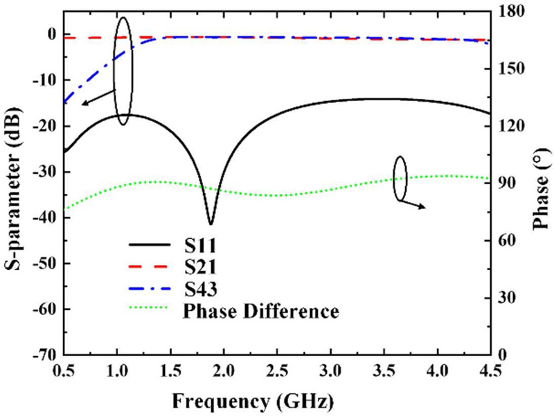
Figure 9: Simulation results of branch-loaded ultra-wideband phase shifter.
III. EXPERIMENTS AND ANALYSIS OF ULTRA-WIDEBAND MAGIC-T NETWORKS
By cascading the 3 dB directional coupler with a 90 phase shifter, the base magic-T network structure can be obtained. To be applicable in a 41 phased-array system, this paper further cascades two two-to-one Wilkinson power dividers onto the basic structure. This results in the ultra-wideband sum-and-difference network that is suitable for phased array systems. The overall structure diagram is shown in Fig. 10. The designed magic-T network includes three layers of metal and two layers of 1 mm-thick FR4 dielectric substrate. Port 1 serves as the sum port, and port 6 is the difference port. Short metal strips on each side of the feed ports are connected to the middle ground layer through metal vias, allowing for the connection of the outer conductor to ground when using SMA connectors. The structure is reciprocal in that signals can be input from ports 1 and 6 and output from ports 2, 3, 4, and 5. Conversely, signals can be input from ports 2, 3, 4, and 5 and output from ports 1 and 6.
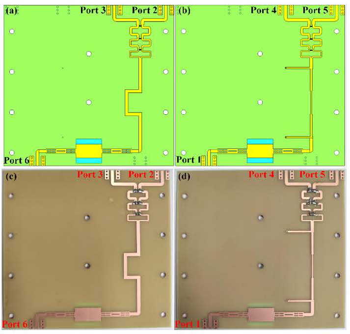
Figure 10: Model structure and fabricated prototype of the magic-T network.
In the actual processing, there are two ways to choose. The first way is to use a multilayer board process, adding a semi-cured sheet between two layers of dielectric substrate, laminated and pressed together. The second way is to process two layers of dielectric substrate separately and then use nylon screws to fix them together. Considering the high cost of the multilayer process and the fact that the semi-cured sheet in the middle of the dielectric can have a subtle effect on the phase shift performance, this design uses the second way of layered processing and screw fixing. By reasonably adjusting the position of the screw holes, they are distributed on both sides and in the middle of the structure, so that there is fundamentally no effect on the performance of the magic-T network. The processed ultra-wideband magic-T network is shown in Fig. 10.
An Agilent E5071C vector network analyzer was used to perform the test on the ultra-wideband magic-T network. The input and output ports to be tested in the magic-T network were connected to the two ports of the vector network, and the remaining ports were connected to the matched load. The overall simulation and experimental results are shown in Figs. 11 and 12.
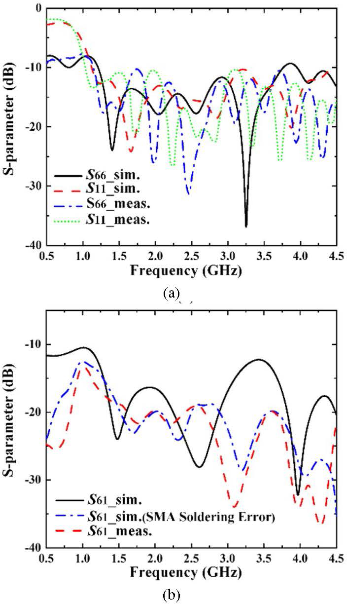
Figure 11: Simulated and measured reflection coefficients and isolation of the proposed magic-T network.
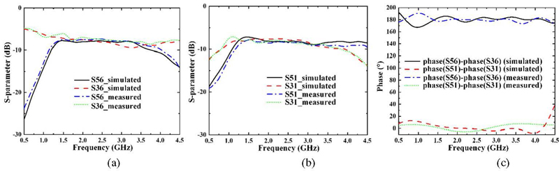
Figure 12: Simulation and experimental results. (a) Transmission coefficient at the difference port 6 input, (b) transmission coefficient at the sum port 1 input, and (c) phase difference of the difference port 6 and sum port 1.
Table 3: Comparison with related research work
| Ref. | Freq. (GHz) | Impedance Bandwidth (%) | Phase Imbalance () | Amplitude Imbalance (dB) | Return Loss (dB) |
Isolation (dB) |
| [10] | 2.42-2.48 | 2.45 | 10 | 0.5 | 15.0 | 25 |
| [7] | 2.5-8 | 105 | 24 | 1.0 | 10.5 | 13 |
| [8] | 8-12 | 40 | 6 | 1.0 | 15.5 | 18 |
| [9] | 5-13 | 89 | 3 | 0.5 | 17.7 | 20 |
| Proposed | 1.2-4 | 108 | 7.6 | 2.1 | 11.0 | 12 |
According to the simulation and experimental results shown in Figs. 11 and 12, it is evident that within the operating frequency range of 1.2 to 4 GHz, the reflection coefficients of the sum-and-difference ports are both below 11 dB, and the isolation, which is defined as the negative of S61, is greater than 12 dB. The transmission coefficient ranges from 7.4 dB to 10.6 dB, and the amplitude imbalance between different output ports is less than 2.1 dB. In terms of the phase of the transmitted signal, the phase error of each output port is less than 2.8 for sum port 1 input and less than 7.6 for difference port 6 input. The slight difference of isolation between the experimental results and the simulation results is mainly attributed to welding errors in the SMA connectors. As shown in Fig. 11, the simulated result, taking into account the parasitic inductance and capacitance resulting from SMA connector soldering errors, is in better agreement with the experimental result.
Although the designed ultra-wideband magic-T network does not completely cover the 1-4 GHz operating band of the phased array system, it has achieved a relative bandwidth of 108% with good amplitude and phase stability, and can be used for direction finding in ultra-wideband systems by generating sum-and-difference beams. The comparison with other relevant research works is shown in Table 3.
IV. CONCLUSION
In this paper, an ultra-wideband sum-difference network based on an interlayer coupled 3 dB directional coupler and a branch-loaded 90 phase shifter is proposed, which operates in the frequency band from 1.2 to 4 GHz with a relative bandwidth of 108%. The experimental results show that the amplitude-phase stability is good. When the input is at the sum port, the phase error at each output port is less than 2.8. For the difference port input, the phase error at each output port is less than 7.6, and the overall amplitude imbalance is less than 2.1 dB. Compared with the traditional sum-difference network, this magic-T network has the advantages of a simple structure and ease of fabrication while providing ultra-wideband performance. It can be used in ultra-wideband phased array systems to generate sum-and-difference beams.
ACKNOWLEDGMENT
This work is supported by the National Natural Science Foundation of China under Grant No. 61971469, the Science and Technology Commission Shanghai Municipality under Grant No. 18ZR1413500, the Open Project Program of the State Key Laboratory of Millimeter Waves under Grant No. K202109 and Fundamental Research Funds of Shaanxi Key Laboratory of Artificially-Structured Functional Materials and Devices (AFMD-KFJJ-21105).
REFERENCES
[1] M. Mansouree and A. Yahaghi, “Planar magic-tee using substrate integrated waveguide based on mode-conversion technique,” IEEE Microw. Wireless Compon. Lett., vol. 26, pp. 307-309, 2016.
[2] F. He, K. Wu, X. P. Chen, L. Han, and W. Hong, “A planar magic-T structure using substrate integrated circuits concept,” in 2010 IEEE MTT-S International Microwave Symposium, pp. 720-723, 2010.
[3] A. Farahbakhsh, “Ka-band coplanar magic-T based on gap waveguide technology,” IEEE Microw. Wirel. Compon. Lett., vol. 30, pp. 853-856, 2020.
[4] J. Wang and T. Ling, “A novel ultra-wideband design of ridged SIW magic-T,” Prog. Electromagn. Res. Lett., vol. 82, pp. 113-120, 2019.
[5] D. Kong, T. Zheng, and F. Hou, “A novel broadband magic-T based on slotline T-junction and microstrip-slotline transition,” in IET International Radar Conference 2013, pp. 0481-0481, 2013.
[6] K. U-yen, E. J. Wollack, J. Papapolymerou, and J. Laskar, “A broadband planar magic-T using microstrip-slotline transitions,” IEEE Trans. Microw. Theory Tech., vol. 56, pp. 172-177, 2008.
[7] Y. Wang, G. Hua, and J. Du, “Design of ultra-wideband magic-T using microstrip/slot coupler and phase shifter,” in 2015 Asia-Pacific Microwave Conference (APMC), pp. 1-3, 2015.
[8] Y. Wu, F. Hou, and D. Kong, “Design of broadband planar magic-T using 3-dB branch-line coupler and phase shifter,” in Proceedings of 2014 3rd Asia-Pacific Conference on Antennas and Propagation, pp. 81-83, 2014.
[9] Y. Chang, M. Yang, J. Fang, Z. Zhao, H. Yan, and Y. Dai, “Design of a novel ultra-wideband planar magic-T,” in 2018 International Conference on Microwave and Millimeter Wave Technology (ICMMT), pp. 1-4, 2018.
[10] Y. Tai, Y. Ren, K. Jiang, and J. M. Zhou, “A novel electrically controlled sum and difference network based on reflective phase shifter,” in 2019 IEEE 3rd Information Technology, Networking, Electronic and Automation Control Conference (ITNEC), pp. 2411-2415, 2019.
[11] A. M. Abbosh and M. E. Bialkowski, “Design of compact directional couplers for UWB applications,” IEEE Trans. Microw. Theory Techn., vol. 55, pp. 189-194, 2007.
[12] D. M. Pozar, Microwave Engineering, 3rd ed. New York: John Wiley & Sons, 2005.
[13] R. K. Mongia, RF and Microwave Coupled-Line Circuits, 2nd ed. London: Artech House, 2006.
[14] M. F. Wong, V. F. Hanna, O. Picon, and H. Baudrand, “Analysis and design of slot-coupled directional couplers between double-sided substrate microstrip lines,” IEEE Trans. Microw. Theory Techn., vol. 39, pp. 2123-2129, 1991.
[15] Y. P. Lyu, “Wideband phase shifters on multimode resonator with improved functionalities” [in Chinese], Ph.D. thesis, Nanjing University of Posts and Telecommunications, 2020.
[16] Y. P. Lyu, L. Zhu, and C. H. Cheng, “Single-layer broadband phase shifter using multimode resonator and shunt /4 stubs,” IEEE Trans. Compon. Packag. Manuf. Technol., vol. 7, pp. 1119-1125, 2017.
BIOGRAPHIES

Yanzhen Shi received bachelor’s degree in communication engineering from Shanghai Normal University, Shanghai, China, in 2021. She is currently pursuing the master’s degree in communication and information system at Shanghai University. Her research interests include phased array antenna, direction of arrival estimation and radar detection.

Dapeng Chu was born in Qufu, Shandong, China, in 1997. He received the master’s degree of communication and information system in Shanghai University, Shanghai 200444, China, in 2023. His research interests include phased array antenna, beaming scanning antenna and metamaterials.

Yongjin Zhou received the B.S. degree in communication engineering from Shandong University, Jinan, China, in 2006, and Ph.D. degree in electromagnetic field and microwave technology from Southeast University, Nanjing, China, in 2011, respectively. From 2009 to 2010, he was a visiting scholar of University of Houston. From 2011 to 2012, he was a software engineer with EEBU of Marvell Technology (Shanghai) Ltd. From 2012 to 2015, he was an Assistant Professor with School of Communication & Information Engineering, Shanghai University, Shanghai, China. From 2015, he was an Associate Professor with School of Communication & Information Engineering, Shanghai University, Shanghai, China. From 2020, he was a Professor with School of Communication & Information Engineering, Shanghai University, Shanghai, China. His current research interests include plasmonic metamaterials, millimeter wave and THz functional devices, wireless energy transmission, computational electromagnetism. He has served as ACES Journal guest editor and is serving as a Youth Editorial Board Member Journal of Electronics & Information Technology. He is serving as a Reviewer for over 20 peer-reviewed journals, such as Nature Electronics, Photonic Research, Optics Letter, Optics Express, Appl. Phys. Express, IEEE Access, IEEE MTT, and IEEE MWCL. He has served as a session chair for several international symposiums.
ACES JOURNAL, Vol. 39, No. 8, 683–690
doi: 10.13052/2024.ACES.J.390803
© 2024 River Publishers