A High-Gain Vivaldi Antenna Loaded with Metasurface for Broadband Applications
Kun Li, Zijie Li, Xiaorui Liu, Shandong Li, Xiaoyun Qu, Zhiqun Yang,and Wei-hua Zong
1College of Electronics and Information
Qingdao University, Qingdao, 266000, China
likun6366@qq.com, lizijie@qdu.edu.cn, lishd@qdu.edu.cn, weihuazong@126.com
2Automation School, Institute of Future
Qingdao University, 266000, Shandong, China
liuxiaorui@qdu.edu.cn
3Shandong Institute of Space Electronic Technology
Yantai 264003, China
selina.qu@163.com, yyangzq@163.com
Submitted On: November 2, 2023; Accepted On: May 7, 2024
ABSTRACT
In this article, a Vivaldi antenna with broad bandwidth and high gain is proposed. The proposed antenna consists of a coplanar Vivaldi antenna (CVA) configuration etched with two rhombus slots at both sides of the radiation arm to improve bandwidth and gain at the low frequencies as well as maintaining antenna miniaturization. A compact broadband metasurface is loaded in the dielectric region between the two exponentially tapered lines to improve radiation performance in a wide frequency range without increasing antenna size. The antenna has been fabricated and measured, obtaining 1.27-9.4 GHz bandwidth covering L/S/C/X and ultra-wideband (UWB) lower bands. The measured gain ranges from 3 dBi to 9.67 dBi. With a miniaturized size of 1001001 mm, good directional radiation pattern and high gain in the whole working band, the proposed antenna is a good candidate for the applications in multi-band coverage systems.
Index Terms: broadband antennas, coplanar Vivaldi antennas (CVA), metasurface, multiband antennas.
I. INTRODUCTION
Multiband coverage ultra-wideband antenna not only has the broadband performance of ultra-wideband antenna, but also covers the operating frequency band of a variety of applications, so that only one broadband antenna is needed to meet the design metrics that can be achieved by combining multiple antennas, such as base station antenna system [1–4], which greatly enhances the performance of electronic information systems, reduces the complexity of system architecture, and effectively alleviates the shortage of frequency spectrum resources and space resources. Vivaldi antenna [5] are widely used in wideband antenna design due to its performance of directional radiation, linear polarization, and low profile. To further improve the antenna’s bandwidth, coplanar Vivaldi antenna (CVA) [6–15], antipodal Vivaldi antenna (AVA) [16–23], and balanced antipodal Vivaldi antenna (BAVA) [24] have been proposed and applied in ground penetrating radar [6–8, 13], medical imaging [9, 10, 16–19], and mobile communication systems [11, 12].
For some applications, such as long-distance point-to-point communication and directional coverage communication, antennas are required with high radiation gain. Using multiple antenna elements to form an antenna array is an effective method to obtain high gain [11]. To reduce the antenna array’s volume and cost, an antenna element with a small size and high gain is preferred. The commonly used methods to improve a Vivaldi antenna element’s gain include integrating a spherical-axicon dielectric lens with the antenna [25, 26], and introducing metasurfaces in the tapered radiation aperture of the antenna [13, 14, 20, 21]. In the forementioned techniques, mounting a dielectric lens with complicated stereoscopic increases the antenna’s volume and fabrication cost, and adding metasurfaces enlarges the antenna’s footprint.
To obtain antenna miniaturization, much work has been done using a high dielectric constant dielectric substrate [16], etching slots in the radiation section [18], [19], and half-cutting the antenna [27]. Arlon AR1000 with a high relative permittivity of 9.8 was used as the substrate of the antenna [16]. Meanwhile, [16, 18, 19] slotted on AVA’s radiation arm to broaden antenna bandwidth at low frequency, but it was ignored that AVA itself has large cross-polarization, which affects antenna radiation performance. In [27], the CVA was half-cut along the antenna’s central axis which resulted in an asymmetrical structure and caused a directional pattern distortion and the directivity deteriorated.
It is challenging to design an antenna with wideband bandwidth, small size, high radiation gain, and good linear performance. In this article, an ultra-wideband Vivaldi antenna based on the traditional CVA is presented, with two rhombus slots etched in both sides of the antenna radiation arm, and the broadband metasurface loaded in the exponential tapered radiation region. The proposed antenna obtains a wide operating bandwidth of 1.27-9.4 GHz with the measured S11 dB. It covers L (1.27-2 GHz), S (2-4 GHz), C (4-8 GHz), and X (8-9.4 GHz) bands as well as UWB (3.1-9.4 GHz) bands, suitable for ground penetrating radar, medical imaging, and communicationsystems.
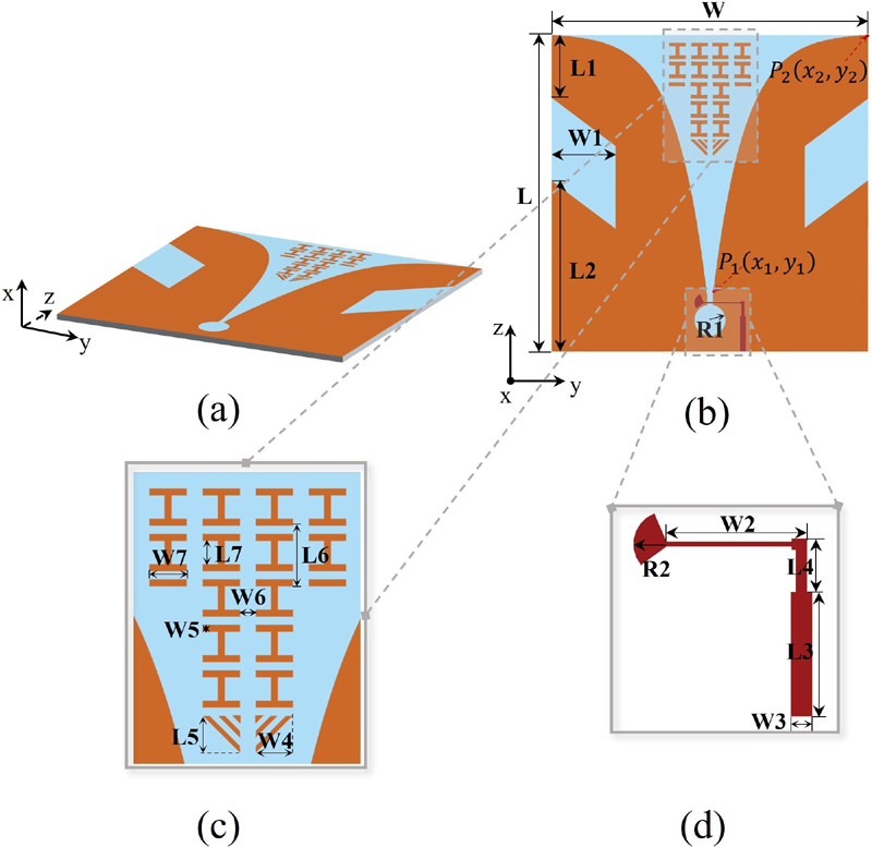
Figure 1: Configuration of the proposed antenna: (a) 3-D view, (b) radiation structure, (c) metasurface structure, and (d) feed structure.
II. ANTENNA CONFIGURATION
The configuration of the proposed antenna is shown in Fig. 1. The proposed antenna is obtained based on a traditional Vivaldi antenna by etching two rhombus-shaped slots on the two radiation arms to improve antenna bandwidth. A broadband metasurface structure is added in the exponentially tapered radiation region to improve antenna gain. The metasurface structure is arranged in the non-metal region with symmetric structure and can maintain miniaturization and improve performance, which is also adopted in [28–32] to reduce mutual coupling. The proposed antenna is fed with a microstrip line connected with an impedance transform line and a sector-shaped balun with a tension angle of 103. The antenna is printed on a 1 mm thick FR4 dielectric substrate, with a dielectric constant of 4.4 and a loss tangent of 0.02. Table 1 lists the optimized geometric dimensions. The proposed antenna was simulated byHFSS 15.0.
Table 1: Dimensions of the proposed antenna
| Par. | Value(mm) | Par. | Value(mm) | Par. | Value(mm) |
| L | 100 | L3 | 10.85 | L6 | 6 |
| W | 100 | W3 | 1.85 | W6 | 2 |
| L1 | 20 | L4 | 4.68 | L7 | 3 |
| W1 | 20 | W4 | 5 | W7 | 5 |
| L2 | 54 | L5 | 5 | R1 | 5 |
| W2 | 12 | W5 | 1 | R2 | 3 |
III. ANTENNA SIMULATION AND ANALYSIS
A. Antenna design
The proposed antenna was designed from a traditional CVA by etching two slots and loading metasurface. To illustrate the design process of the proposed antenna, three reference antennas (Ant I, Ant II, and Ant III) are presented in Fig. 2. The antennas’ reflection coefficients and radiation patterns are given in Figs. 3 and 4, respectively.
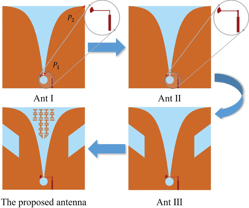
Figure 2: Evolution of the proposed antenna.
As shown in Fig. 2 (a), Ant I is a traditional CVA fed with a step-shaped microstrip and fan-shaped balun. The step-shaped microstrip acts as an impedance transformer to obtain wideband impedance matching. The theoretical formula of the exponential tapered curve of a traditional CVA is:
| (1) |
where the values A and B in (1) can be calculated from the coordinates of the beginning point P (x, y) and the terminal point P (x, y) of the exponential tapered curve by the following equations:
| (2) |
| (3) |
where the value of c is optimized as 0.1 which determines the curvature of the exponential tapered curve and affects the impedance bandwidth of theantenna.
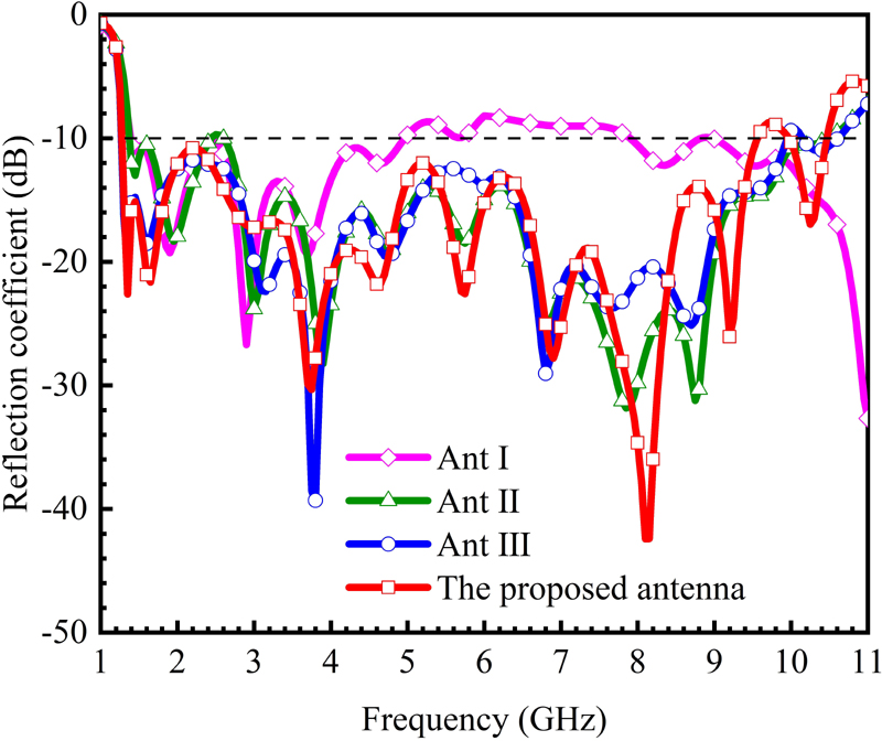
Figure 3: Reflection coefficients of reference antennas and the proposed antenna.
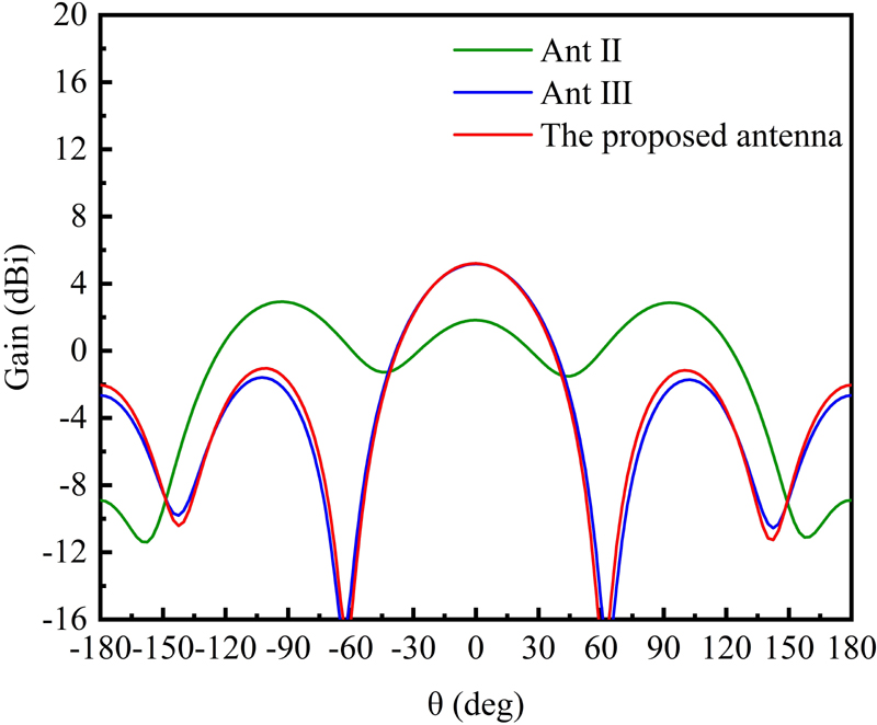
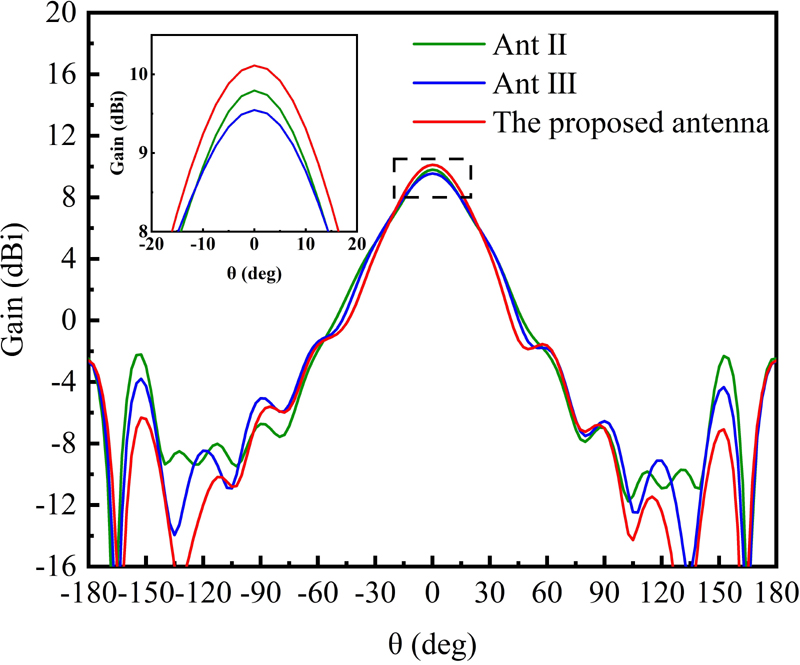
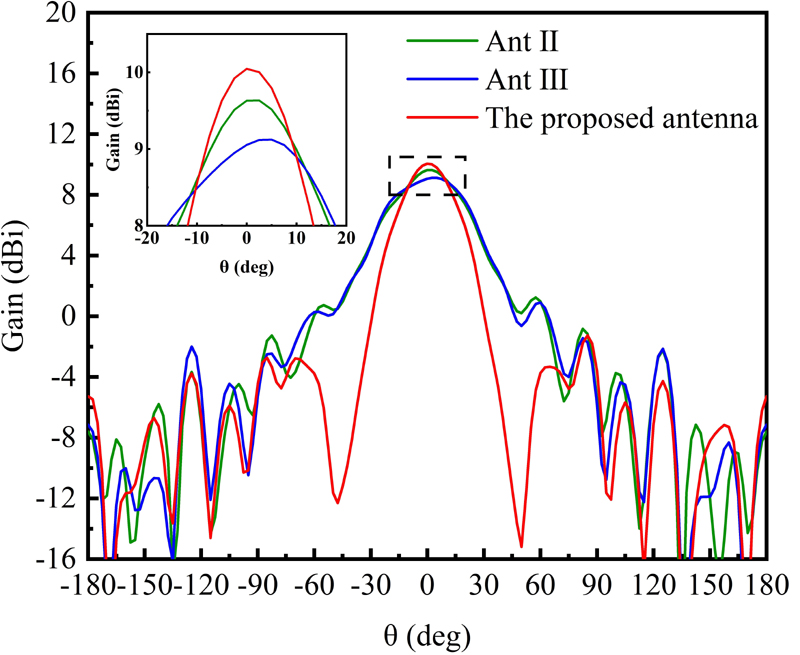
Figure 4: The far-field radiation pattern in yoz-plane of reference antennas and the proposed antenna at (a) 1.4 GHz, (b) 6 GHz, and (c) 8 GHz.
The exponentially curved profile was proven to be a self-scaling configuration providing frequency-independent behavior [33]. As depicted in Fig. 3, Ant I’s dB bandwidth is 1.4-5 GHz. The antenna’s reflection coefficients are higher than dB at frequencies 5-7.9 GHz. A second-ordered impedance transformer is adopted in Ant II’s feeding strip to improve the impedance matching at higher frequencies 5-10.4 GHz. However, the reflection coefficients at 2.4-2.6 GHz are slightly higher than dB. A rhombus slot is etched in Ant III at the side edge of each radiation patch to reduce reflections at lower frequencies. As shown in Fig. 3, Ant III obtains low reflection coefficients both in lower and higher frequencies with bandwidth covering 1.27-9.9 GHz. Based on Ant III, a broadband metasurface is added in the opening region of the radiation part. As shown in Fig. 3, the proposed antenna’s reflection coefficients remain similar to Ant III at the lower frequencies, whereas they become a bit higher at frequencies above 8 GHz. The proposed antenna has a bandwidth of 1.27-9.4 GHz, which is a bit narrower than Ant III. The adoption of a metasurface is to improve antenna radiation pattern and gain which is discussed in thefollowing.

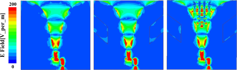
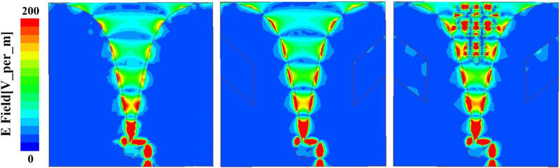
Figure 5: The electric field distributions of Ant II, Ant III, and the proposed antenna at: (a) 1.4 GHz, (b) 6 GHz, and (c) 8 GHz.
As shown in Fig. 4 (a), Ant II has two side lobes at =95 with higher gain values than the main beam at =0 at 1.4 GHz, which are caused by the electric field distributing along the edge of the bottom plate edge as shown in Fig. 5 (a). Ant III and the proposed antenna have a lower side lobe at 1.4 GHz. As shown in Fig. 4 (b), Ant III and the proposed antenna have higher peak gain at =0 and lower back lobe at =150 at 6 GHz. As shown in Fig. 4 (c), the proposed antenna has a higher peak gain and narrower main beam than Ant III and Ant II at 8 GHz. These results indicate that adding the two rhombus-shaped slots can improve antenna radiation patterns at lower frequencies, and adding the metasurface can improve antenna radiation patterns at higher frequencies. The broadband metasurface has been well designed and maintains a wide bandwidth covering 1.27-9.4 GHz as shown in Fig. 3.
B. Electric field distribution analysis
The electric field distributions of Ant II, Ant III, and the proposed antenna on the top layers at 1.4 GHz, 6 GHz, and 8 GHz are given in Fig. 5. As shown in Fig. 5 (a), strong electric fields distribute at the bottom edge near the feeding port for Ant II, resulting in a sidelobe higher than the main beam at 1.4 GHz (shown in Fig. 4 (a)). It can also be seen from Fig. 5 (a) that the electric fields distribution at the bottom edges of Ant III and the proposed antenna become much weaker than Ant II, which results in a lower sidelobe as shown in Fig. 4 (a). Comparing electric field distributions of Ant III and the proposed antenna at 6 GHz and 8 GHz shown in Figs. 5 (b) and (c), it can be seen that more electric fields are introduced in the area near the opening region of the two exponential curves with the adoption of the metasurface which improves radiation pattern at higher frequencies as shown in Figs. 4 (b) and (c).
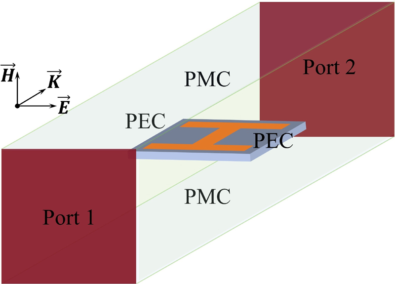
Figure 6: Simulation setup of the unit cell.
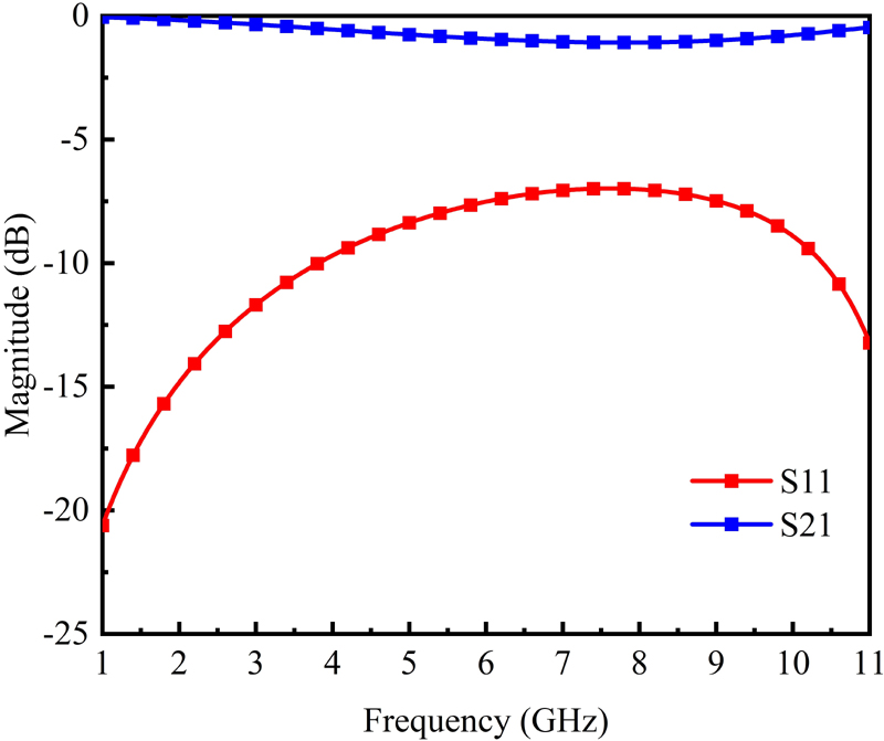
Figure 7: Simulated S-parameters of the metasurface unit cell.
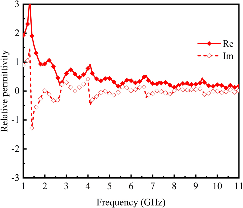
Figure 8: Retrieved relative permittivity of the metasurface.
S-parameters of the metasurface unit cell are simulated by using the model shown in Fig. 6. PEC and PMC boundary conditions are set in the model. Figure 7 shows the simulated S-parameters. As shown, S is less than dB, and S is higher than dB in the frequency band of 1-11 GHz, which indicates that the metasurface structure has broadband performance. The relative permittivity of the broadband metasurface has been simulated and computed by using the equivalent medium theory [34]. Figure 8 shows simulated results. As can be seen, the values of relative permittivity are around 1 at frequencies higher than 1.5 GHz, which provides good impedance matching between the antenna and the air and improves the radiation performance.
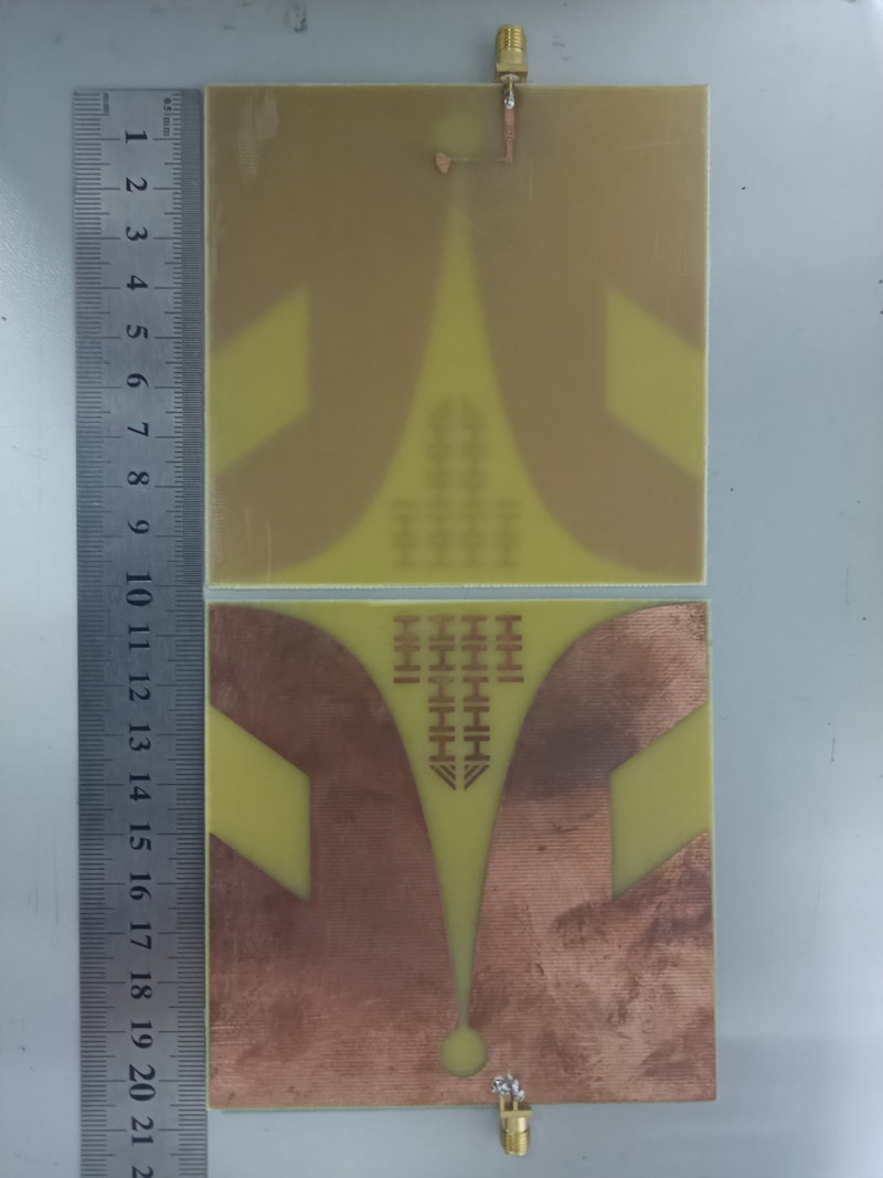
Figure 9: Photograph of the fabricated antenna.
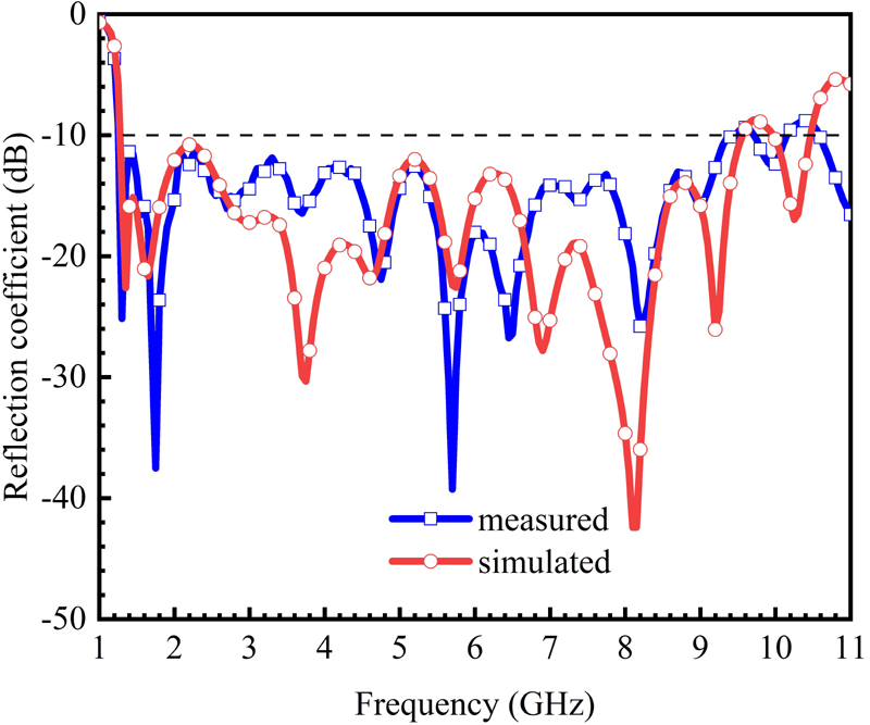
Figure 10: Simulated and measured reflection coefficients.
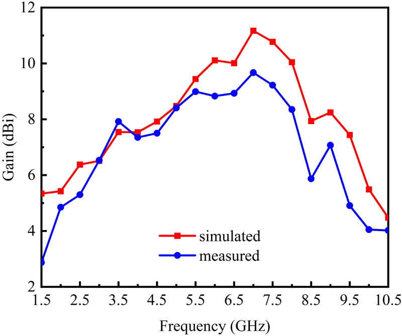
Figure 11: Simulated and measured gain.
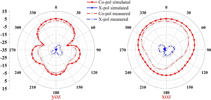
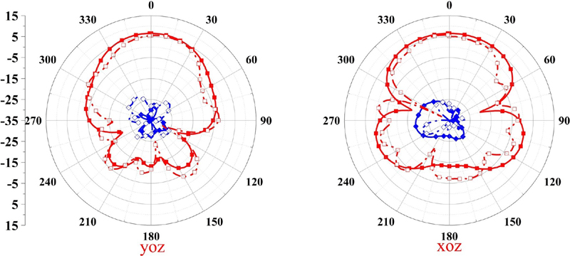
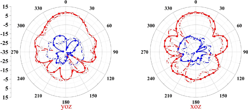
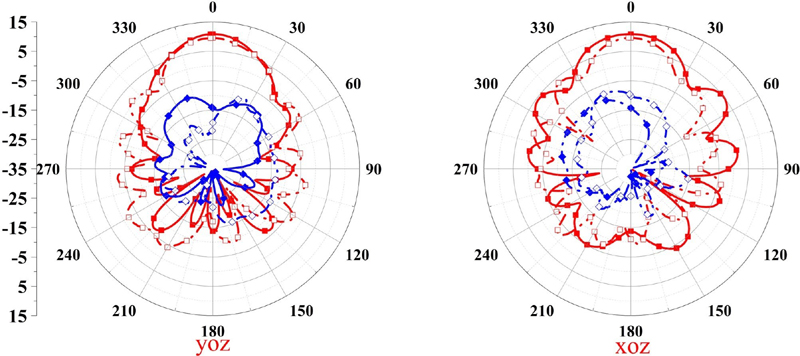
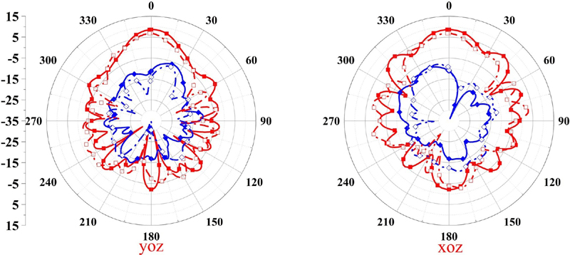
Figure 12: Radiation pattern of xoz and yoz planes of the antenna at (a) 1.5 GHz, (b) 3 GHz, (c) 5 GHz, (d) 7 GHz, and (e) 9 GHz.
Table 2: Comparison of the proposed antenna with published literatures
| Ref. | Size () | BW(GHz) | RBW(%) | Gain(dBi) |
| [13] | 0.70.670.0035 | 0.7-2.1 | 100 | 0.6-2 |
| [15] | 0.290.20.008 | 2.9-13.55 | 129.5 | 1.8-6.91 |
| [18] | 0.750.750.008 | 1.5-3.3 | 75 | 6.2-8.2 |
| [19] | 0.510.510.013 | 2.35-3.79 | 46.9 | 4-7.35 |
| [21] | 0.61.30.0025 | 1-28 | 186.2 | 4.9-14.4 |
| Pro. | 0.420.420.0042 | 1.27-9.4 | 152.4 | 3-9.67 |
is the free space wavelength at the lowest operational frequency.
RBW is the relative bandwidth.
IV. RESULTS AND DISCUSSION
The prototype of the proposed antenna has been fabricated and measured. Figure 9 shows photographs of the fabricated antenna. Measured reflection coefficients are illustrated in Fig. 10. It can be observed that the measurement agrees well with the simulation, and the measured bandwidth with reflection coefficient lower than dB is 1.27-9.4 GHz, covering L (1.27-2 GHz), S (2-4 GHz), C (4-8 GHz), X (8-9.4 GHz), and UWB lower (3.1-4.5 GHz) bands.
The simulated and measured gain plots are shown in Fig. 11. Figure 12 presents the radiation pattern in xoz and yoz planes of the antenna at 1.5 GHz, 3 GHz, 5 GHz, 7 GHz, and 9 GHz, respectively. As shown, measurement agrees well with simulation, and the antenna has good directional radiation and linear polarization. The measured gain is higher than 3 dBi and peak gain reaches to 9.67 dBi in the working band. Table 2 shows comparison of the proposed antenna with published literatures. The proposed antenna has a wider bandwidth than the ones in [13, 15, 18, 19] and a smaller electrical size than the one in [21].
V. CONCLUSION
A miniaturized, high-gain, multi-band coverage ultra-wideband antenna has been proposed and fabricated in this article. The proposed antenna has an excellent impedance matching bandwidth of 1.27-9.4 GHz with reflection coefficient below dB and stable directional radiation performance. The measured gain ranges from 3 dBi to 9.67 dBi. The overall size of the antenna is 0.420.420.0042. The proposed antenna is a promising and economical candidate for applications such as detection radar, medical imaging, and mobile communication.
ACKNOWLEDGMENT
This work was supported by the Natural Science Foundation of Shandong Province, China (No. ZR2020MF023).
REFERENCES
[1] M. Shirazi, J. Huang, T. Li, and X. Gong, “A switchable S-/C-band antenna array with dual polarization and modularity,” IEEE Transactions on Antennas and Propagation, vol. 68, no. 2, pp. 783-794, Feb. 2020.
[2] G. W. Yang and S. Zhang, “A dual-band shared-aperture antenna with wide-angle scanning capability for mobile system applications,” IEEE Transactions on Vehicular Technology, vol. 70, no. 5, pp. 4088-4097, May 2021.
[3] D. He, Y. Chen, and S. Yang, “A low-profile triple-band shared-aperture antenna array for 5G base station applications,” IEEE Transactions on Antennas and Propagation, vol. 70, no. 4, pp. 2732-2739, Apr. 2022.
[4] Y. Li and Q. X. Chu, “Dual-band base station antenna array using the low-band antenna as parasitic decoupler,” IEEE Antennas and Wireless Propagation Letters, vol. 21, no. 7, pp. 1308-1312, July 2022.
[5] P. J. Gibson, “The Vivaldi aerial,” in 9th European Microwave Conference, pp. 101-105, 1979.
[6] M. García-Fernández, G. Álvarez-Narciandi, Y. Álvarez López, and F. Las-Heras, “Array-based ground penetrating synthetic aperture radar on board an unmanned aerial vehicle for enhanced buried threats detection,” IEEE Transactions on Geoscience and Remote Sensing, vol. 61, pp. 1-18, 2023.
[7] M. García Fernández, G. Álvarez Narciandi, A. Arboleya, C. Vázquez Antuña, F. L. H. Andrés, and Y. Álvarez López, “Development of an airborne-based GPR system for landmine and IED detection: antenna analysis and intercomparison,” IEEE Access, vol. 9, pp. 127382-127396, Sep. 2021.
[8] H. H. Sun, W. Cheng, and Z. Fan, “Diameter estimation of cylindrical metal bar using wideband dual-polarized ground-penetrating radar,” IEEE Transactions on Instrumentation and Measurement, vol. 72, pp. 1-14, 2023.
[9] P. Phasukkit, “Non-ionic deep learning-driven IR-UWB multiantenna scheme for breast tumor localization,” IEEE Access, vol. 10, pp. 4536-4549, Jan. 2022.
[10] K. C. Santos, C. A. Fernandes, and J. R. Costa, “Validation of a compact microwave imaging system for bone fracture detection,” IEEE Access, vol. 11, pp. 63690-63700, 2023.
[11] P. I. Bantavis, C. I. Kolitsidas, T. Empliouk, M. Le Roy, B. L. G. Jonsson, and G. A. Kyriacou, “A cost-effective wideband switched beam antenna system for a small cell base station,” IEEE Transactions on Antennas and Propagation, vol. 66, no. 12, pp. 6851-6861, Dec. 2018.
[12] Y. Dong, J. Choi, and T. Itoh, “Vivaldi antenna with pattern diversity for 0.7 to 2.7 GHz cellular band applications,” IEEE Antennas and Wireless Propagation Letters, vol. 17, no. 2, pp. 247-250, Feb. 2018.
[13] H. Cheng, H. Yang, Y. Li, and Y. Chen, “A compact Vivaldi antenna with artificial material lens and sidelobe suppressor for GPR applications,” IEEE Access, vol. 8, pp. 64056-64063, Apr. 2020.
[14] M. Singh and M. S. Parihar, “Gain improvement of Vivaldi MIMO antenna with pattern diversity using bi-axial anisotropic metasurface for millimeter-wave band application,” IEEE Antennas and Wireless Propagation Letters, vol. 22, no. 3, pp. 621-625, Mar. 2023.
[15] S. Saleh, W. Ismail, I. S. Zainal Abidin, M. H. Jamaluddin, M. H. Bataineh, and A. S. Al-Zoubi, “Novel compact UWB Vivaldi nonuniform slot antenna with enhanced bandwidth,” IEEE Transactions on Antennas and Propagation, vol. 70, no. 8, pp. 6592-6603, Aug. 2022.
[16] M. Wang, L. Crocco, S. Costanzo, R. Scapaticci, and M. Cavagnaro, “A compact slot-loaded antipodal Vivaldi antenna for a microwave imaging system to monitor liver microwave thermal ablation,” IEEE Open Journal of Antennas and Propagation, vol. 3, pp. 700-708, July 2022.
[17] M. Y. Ren, Z. W. Cheng, L. H. Wu, H. M. Zhang, S. X. Zhang, X. Y. Chen, D. Xing, and H. Qin, “Portable microwave-acoustic coaxial thermoacoustic probe with miniaturized Vivaldi antennas for breast tumor screening,” IEEE Transactions on Biomedical Engineering, vol. 70, no. 1, pp. 175-181, Jan. 2023.
[18] A. M. de Oliveira, A. M. de Oliveira Neto, M. B. Perotoni, N. Nurhayati, H. Baudrand, A. de Carvalho, Jr, and J. F. Justo, “A fern antipodal Vivaldi antenna for near-field microwave imaging medical applications,” IEEE Transactions on Antennas and Propagation, vol. 69, no. 12, pp. 8816-8829, Dec. 2021.
[19] M. Y. I. Yazid, M. H. Baharuddin, M. S. Islam, M. T. Islam, and A. F. Almutairi, “A Sierpinski arrowhead curve slot Vivaldi antenna for microwave head imaging system,” IEEE Access, vol. 11, pp. 32335-32347, Apr. 2023.
[20] O. Yesilyurt and G. Turhan-Sayan, “Metasurface lens for ultra-wideband planar antenna,” IEEE Transactions on Antennas and Propagation, vol. 68, no. 2, pp. 719-726, Feb. 2020.
[21] X. Shi, Y. Cao, Y. Hu, X. Luo, H. Yang, and L. H. Ye, “A high-gain antipodal Vivaldi antenna with director and metamaterial at 1-28 GHz,” IEEE Antennas and Wireless Propagation Letters, vol. 20, no. 12, pp. 2432-2436, Dec. 2021.
[22] B. Tariq, M. Amjad, and A. Aziz, “Computational analysis for miniaturization of tapered slot antenna using elliptical conducting loaded strips,” Applied Computational Electromagnetics Society Journal, vol. 37, no. 6, pp. 672-678, June2022.
[23] N. Kwon, S. Ahn, and W. Lee, “Wideband printed antipodal Vivaldi antenna using straight slots for UHF DVB-T/T2 applications,” The Applied Computational Electromagnetics Society Journal, vol. 37, no. 6, pp. 726-732, June 2022.
[24] H. T. Chou and Y. J. Lin, “An optimum design of paired balanced antipodal Vivaldi antennas with mirror-imaged symmetric architectures for ultra-broadband characteristics from microwave to millimeter-wave frequency ranges,” IEEE Access, vol. 10, pp. 99516-99524, Sep. 2022.
[25] R. Cicchetti, V. Cicchetti, A. Faraone, and O. Testa, “A class of lightweight spherical-axicon dielectric lenses for high gain wideband antennas,” IEEE Access, vol. 9, pp. 151873-151887, Oct. 2021.
[26] R. Cicchetti, V. Cicchetti, A. Faraone, L. Foged, and O. Testa, “A compact high-gain wideband lens Vivaldi antenna for wireless communications and through-the-wall imaging,” IEEE Transactions on Antennas and Propagation, vol. 69, no. 6, pp. 3177-3192, June 2021.
[27] B. Wu, X. Y. Sun, H. R. Zu, H. H. Zhang, and T. Su, “Transparent ultrawideband halved coplanar Vivaldi antenna with metal mesh film,” IEEE Antennas and Wireless Propagation Letters, vol. 21, no. 12, pp. 2532-2536, Dec. 2022.
[28] S. Y. Luo, Y. S. Li, and W. L. Shi, “A dual-frequency antenna array with mutual coupling reduction via metamaterial structures,” in 2018 IEEE International Symposium on Antennas and Propagation & USNC/URSI National Radio Science Meeting, pp. 1385-1386, 2018.
[29] K. Yu, Y. S. Li, and X. G. Liu, “Mutual coupling reduction of a MIMO antenna array using 3-D novel meta-material structures,” Applied Computational Electromagnetics Society Journal, vol. 33, no. 7, pp. 758-763, July 2018.
[30] S. Y. Luo, Y. S. Li, Y. F. Xia, G. H. Yang, L. J. Sun, and L. Zhao, “Mutual coupling reduction of a dual-band antenna array using dual-frequency metamaterial structure,” Applied Computational Electromagnetics Society Journal, vol. 34, no. 3, pp. 403-410, 2019.
[31] F. Liu, J. Y. Guo, L. Y. Zhao, G. L. Huang, Y. S. Li, and Y. Z. Yin, “Ceramic superstrate-based decoupling method for two closely packed antennas with cross-polarization suppression,” IEEE Transactions on Antennas and Propagation, vol. 69, no. 3, pp. 1751-1756, Mar. 2021.
[32] J. Y. Guo, F. Liu, L. Y. Zhao, Y. Z. Yin, G. L. Huang, and Y. S. Li, “Meta-surface antenna array decoupling designs for two linear polarized antennas coupled in H-plane and E-plane,” IEEE Access, vol. 7, pp. 100442-100452, Aug. 2019.
[33] M. Chiappe and G. L. Gragnani, “Theoretical and numerical analysis of the self-scaling properties of the exponentially tapered slot-line antenna,” Microwave and Optical Technology Letters, vol. 45, no. 6, pp. 485-491, June 2005.
[34] D. R. Smith, D. C. Vier, T. Koschny, and C. M. Soukoulis, “Electromagnetic parameter retrieval from inhomogeneous metamaterials,” Phys. Rev. E, vol. 71, no. 3, pp. 1-11, Mar. 2005.
BIOGRAPHIES

Kun Li was born in Yichun, Jiangxi Province, China, in 1997. In 2020, he received the B.S. degree in communication engineering from Hunan Institute of Science and Technology, Yueyang, Hunan Province, China. He is currently pursuing the M.S. degree in new-generation electronic information technology at Qingdao University, Qingdao, China. His current research interest is in broadband high gain antenna and antenna array.

Zijie Li received the B.S. degree in Electromagnetic Field and Wireless Technology from the Nanjing University of Posts and Telecommunications, Nanjing, China, in 2021. He is currently pursuing the M.S. degree with the school of electronic information, Qingdao University, Qingdao, China. His current research interests include circularly polarized antennas, metamaterial-based antennas, and reconfigurable antennas.

Xiaorui Liu received the Ph.D. degree from Ocean University of China, Qingdao, Shandong Province, China, in 2019. From September 2017 to December 2018, he was a joint Ph.D. student at the Electromagnetic Compatibility Center of Missouri University of Technology. Since 2019, he joined Qingdao University, Qingdao, Shandong Province, China as an assistant professor. His research interests include robot-human-computer interaction, electronic information and detection technology, and embedded systems.

Shandong Li was born in Dongying, Shandong Province, China, in 1970. He received the B.S. from Shandong University, M.S. degree from Institute of Metal Research of the Chinese Academy of Sciences, and the Ph.D. degree from Nanjing University. He then pursued postdoctoral research in physical electronics at Nanjing University and Tsinghua University in Taiwan. He has been a visiting scholar at Northeastern University in the United States and Tübingen University and Münster University in Germany. He taught at China University of Petroleum (1996-2000) and Fujian Normal University (2004-2011). Now he is a Distinguished Professor and doctoral supervisor at Qingdao University. His research interests include superconducting quantum interference devices, magnetic materials, microwave materials and integrated devices, biochip technology, and new energy materials.

Xiaoyun Qu was born in Yantai City, Shandong Province, China, in 1974. She received the B.S. in applied mathematics from Yantai University, in 1996, and M.S. degree in electromagnetic fields and microwave technology from Nanjing Electronics research Center, Nanjing, Jiangsu Province, China, in 1990. She is with Shandong Institute of Space Electronic Technology, Yantai, China, as a Senior Engineer. Her research interest is antenna design.

Zhiqun Yang received the Ph.D. degree in communication and information system from Nanjing University of Technology, Nanjing, Jiangsu Province, China, in 2003. He is with Shandong Institute of Space Electronic Technology, China Aerospace Science and Technology Corporation, Yantai, China, as a Senior Engineer. His research interest is signal processing and communication.

Wei-hua Zong was born in Penglai City, Shandong Province, China, in 1975. She received the B.S. in applied mathematics from Yantai University, in 1997, M.S. degree in electromagnetic fields and microwave technology from Nanjing Electronics research Center, Nanjing, Jiangsu Province, China, in 2000, and the Ph.D. degree in electromagnetic fields and microwave technology from Xidian University, Xian, Shanxi Province, China, in 2004. In 2004, she joined Qingdao University, Qingdao, Shandong Province, China as a lecture. Since 2005, she has been an Associate Professor in Qingdao University. From February to August 2010, she was a Visiting Scholar Assistant with Electrical and Computation Engineering Department, National University of Singapore. Her research interests include antenna design and electromagnetic material measurement.
ACES JOURNAL, Vol. 39, No. 10, 876–884
doi: 10.13052/2024.ACES.J.391005
© 2024 River Publishers