A Focused Metasurface Lens Antenna with Gain Enhancement
Yu Dong and Xing Chen
College of Electronic and Information Engineering
Sichuan University, Chengdu 610064, China
yudong0327@163.com, xingc@live.cn
Submitted On: November 6, 2023; Accepted On: May 16, 2024
ABSTRACT
A specialized metasurface has been developed for lens antenna applications. This innovative metasurface unit cell comprises five metallic layers and four dielectric layers. Each metallic layer consists of a pair of back-to-back split resonant rings. The proposed unit cell is highly effective with a transmission phase coverage exceeding 360 and a transmission amplitude larger than 70% at X-band (8.8-11.2 GHz). The unit cell has been thoroughly designed, fabricated and tested. To verify the present unit cell, a metasurface array with 2727 elements is designed. An X-band horn antenna is used as the feed source. Simulation and measurement results show that the electromagnetic wave from the feed horn is focused within the operating band, resulting in a measured gain of 16.9 dB at 9 GHz and 19.2 dB at 11 GHz. Thus, a gain enhancement of 5.4 dB at 9 GHz and 5.7 dB at 11 GHz are obtained, making it a good reference for engineering applications.
Index Terms: metasurface, split resonant ring, wideband.
I. INTRODUCTION
Metasurface technology has rapidly developed and been applied in recent years. Its main function is to regulate the amplitude and phase of electromagnetic waves to achieve various performances, such as digitally reconfigurable antennas [1–5], microwave phase shifters [6], RCS reduction [7], antenna isolation enhancement [8], and filtering antenna [9]. Satellite communication technology has become a fascinating research field, with the main operating frequencies being C-band (4-8 GHz), X-band (12-18 GHz), and Ku-band (27-40 GHz). The currently used satellite communication antennas are mainly parabolic, array, and high gain horn lens antennas. However, metasurface-based transmitarray (TA) antennas or reflect array antennas have shown potential advantages, such as reducing costs, improving gain, and enhancing bandwidth, compared to the commonly used satellite communication antennas [10–19]. Additionally, metasurface technology is more flexible and performs excellently in multifunctional antennas, such as polarization reconfigurable antennas [20–25].
Several relevant papers have been published on wideband-focused metasurface. [26] proposes a double-layer TA consisting of four metal vias and two patches with a 1-dB gain bandwidth of 9.6% (20.1-22.2 GHz). A similar design method is also presented in [27], with a 1-dB gain bandwidth of 9% (17.2-18.8 GHz). In [28], a TA antenna based on a hybrid frequency selective surface (FSS) is proposed, but only a narrow band (at 10 GHz) is introduced. In [29], a TA made of three metallic layers with an air gap is introduced. The proposed TA has a 1-dB gain bandwidth of 15.5%, but the air gap increases the profile of the entire antenna system. In [30], a metasurface that combines the functionalities of TA and reflectarray (RA) is presented. The electromagnetic wave focusing function depends on the polarization mode of the incoming wave, and a 1-dB gain bandwidth (9.14%) from 9.4 to 10.3 GHz is obtained.
This paper studies the wideband focusing metasurface lens antenna with gain enhancement. The metasurface unit cell comprises five metallic layers of pairs of back-to-back split resonant rings. The unit cell comprises five metallic layers and four dielectric layers. The proposed unit cell is highly effective with a transmission phase coverage exceeding 360 and a transmission amplitude above 70% at X-band (8.8-11.2 GHz). The unit cell has been designed, fabricated and tested. To verify the present unit cell, a metasurface array with 2727 elements is designed, and a X-band horn antenna is used as a feed source. Simulation and measurement results show that the electromagnetic wave from the feed horn is focused within the operating band. When an electromagnetic wave from an X-band feed horn is directed towards it, the metasurface focuses the waves within the operating band that covers 8.8-11.2 GHz. The measured gain is 16.9 dB at 9 GHz and 19.2 dB at 11 GHz. This represents a gain enhancement of 5.4 dB at 9 GHz and 5.7 dB at 11 GHz. The metasurface provides a 1-dB gain bandwidth (5.7%) from 8.8 to 11.2 GHz.
II. DESIGN OF METASURFACE
Figure 1 depicts the proposed unit cell’s fundamental structure, which comprising five metallic layers. Each layer consists of a pair of back-to-back split resonant rings. The dielectric material, Rogers RO3035, is 2.5 mm thickness and has a relative dielectric constant of 3.5. The metasurface unit cell is analyzed using periodic boundaries in the x and y directions through simulation software CST Studio Suite. The transmission phase is highly sensitive to the cutting length s of the split resonant ring. Thus, parameter s is optimized to meet the required phase variation while keeping the other parameters constant.
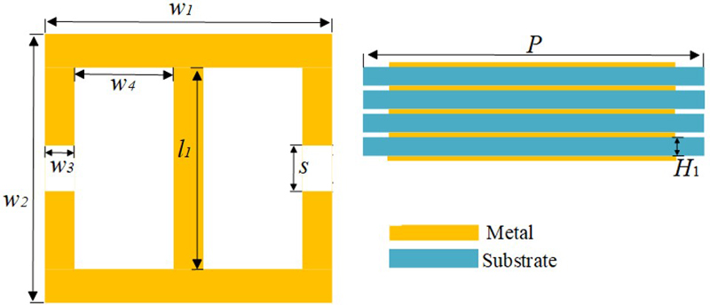
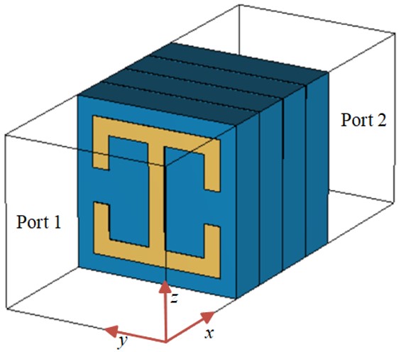
Figure 1: (a) Geometry model and structure parameters. (b) Configuration of the unit cell.
In general, the metasurface unit cell can be regarded as a two-port network, and its performance is characterized by transmission and reflection coefficients. In this paper, our proposed transmissive metasurface has high transmission coefficients and low reflection coefficients. Therefore, its transmission matrix is concerned, and it can be expressed as the following matrix:
| (1) |
where T and T represent the co-polarization transmission coefficients of x-polarized and y-polarized incident waves, and T and T represent the cross-polarization transmission coefficients of x-polarized and y-polarized incident waves. Since the proposed metasurface structure is symmetric about both the x- and y-axes, cross-polarization transmission coefficients (T and T) can be regarded as approximately zero. Figure 2 shows the transmission coefficients of the proposed metasurface unit cell with s 0.1 mm. We can see that the cross-polarization transmission coefficients (T and T) are close to zero. At the same time, the co-polarization transmission coefficient T is also close to 0 at the concerned frequency. The co-polarization transmission coefficient T is greater than 0.7 over a large bandwidth range (8.8-11.2 GHz). The proposed metasurface unit has a grating-like effect, which can filter out x-polarized waves to a certain extent and let y-polarized waves pass through completely.
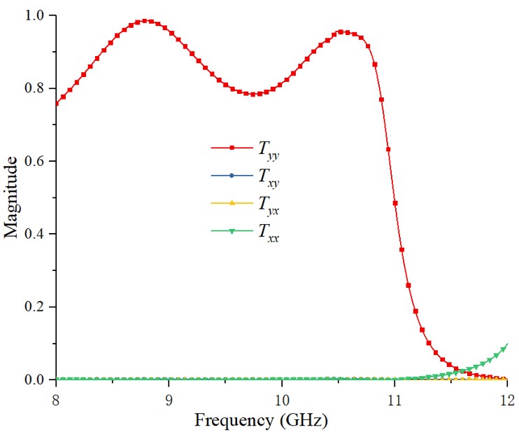
Figure 2: Transmission coefficients of the proposed metasurface unit cell with s 0.1 mm.
We can explain the selective transmission function of the unit cell structure by analyzing the electric field distribution. We give the z-component electric field distribution two resonant peaks of 9 GHz and 10.5 GHz. Figure 3 (a) shows the electric field distribution when y-polarization incident on the metasurface unit cell is 9 GHz. It can be seen that there are two pairs of electric field gathering points with opposite intensity at the opening on both sides, forming two pairs of electric dipoles which transmit y-polarized incident waves and carry certain phase mutations as the basis for multi-layer phase superposition. Figure 3 (b) shows the electric field distribution generated by x-polarization incident wave of 9 GHz. No electric dipoles are generated in the figure, indicating that the metasurface structure cannot generate effective resonance for x-polarized waves. Figures 3 (c) and (d) show the electric field distribution of y-polarized and x-polarized incident waves at 10.5 GHz, respectively. Similarly, y-polarized incident waves can generate two pairs of electric dipoles on the metasurface, while x-polarized waves have no such effect. Therefore, we explain the rationality of metasurface energy transmitting y-polarized incident waves while shielding x-polarized incident waves.
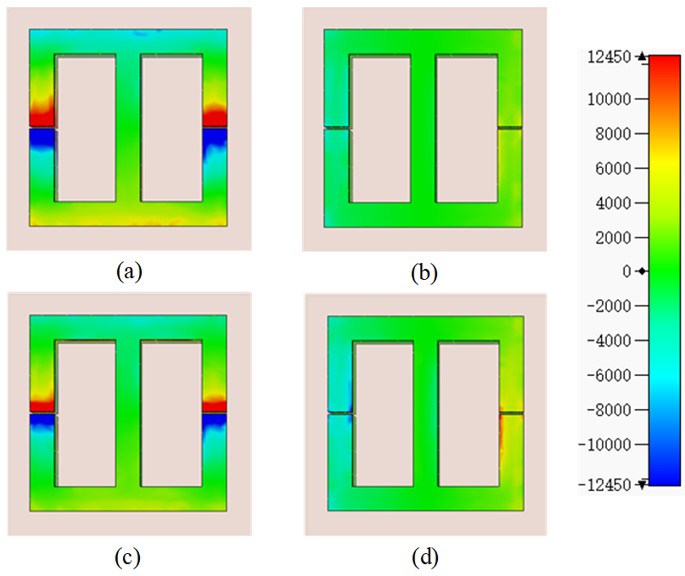
Figure 3: Electric field distribution of the proposed metasurface unit with s 0.1 mm: (a) y-polarization incident wave at 9 GHz, (b) x-polarization incident wave at 9 GHz, (c) y-polarization incident wave at 10.5 GHz, and (d) x-polarization incident wave at 10.5 GHz.
III. RESULTS AND DISCUSSION
Figure 4 shows the unit cell’s simulated transmission magnitude and phase against parameter s under different frequencies. Seen from Fig. 4 (a), the transmission magnitude exceeds 0.7, covering the band 8.8-11.2 GHz when parameter s varies from 0.1 mm to 6.0 mm. The transmission phase is given in Fig. 4 (b). The minimum transmission phase range of about 300 is realized at around 8 GHz, and a transmission phase range over 360 is obtained across 8.8-11.2 GHz. It is reliable to design a metasurface lens antenna within X-band with an elaborate design. The parameters of the proposed unit cell are: W 8, W 8, W 1, W 2.5, l 6, H 2.5, and P 10 (unit mm). It is worth noting that by changing the value of the parameter s, the phase of the transmitted y-polarized wave can be changed, so free phase manipulation can be achieved.
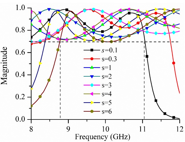
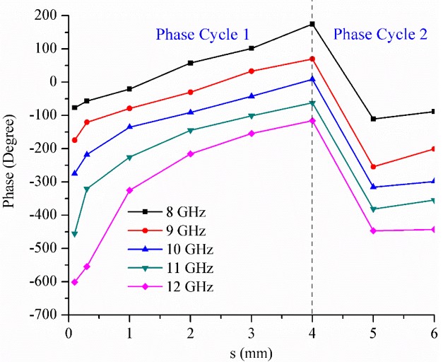
Figure 4: (a) Transmission magnitude of unit cell. (b) Transmission phase of unit cell.
To efficiently focus the incoming electromagnetic wave, phase difference distribution in the yoz-plane should meet the following [29–31]:
| (2) |
where p and F is the periodicity and focal distance of unit cell, m(n) is defined as the number of unit cells in x(y)-direction, is the free space wavelength, and is the phase difference between the unit cell located at mp, np and the unit cell at the initial center (m 0, n 0). The proposed metasurface is designed according to the spatial phase difference distribution in equation (2) to verify the present unit cell. The metasurface is encoded by using an eight-order phase gradient method, the eight unit cells are named No. 1, No. 2, No. 3, No. 4, No. 5, No. 6, No. 7, and No. 8, respectively. The designed metasurface contains three bits of phase information. Each unit cell is designed to have constant phase difference 45. The phase difference distribution is shown in Fig. 5, which demonstrates that a transmission phase coverage exceeding 360 is obtained within an operation wavelength. The value of s is selected to be 0.1, 0.3, 1, 2, 3, 4, 5, or 6, which formed the eight different phase difference unit cells, corresponding to the phase information in Fig. 5. The designed layout is shown in Fig. 6 (a). Figure 6 (a) shows the simulated layout configuration of the proposed metasurface lens antenna. An X-band horn is used as the feed source. It is placed a focal distance of D. The electromagnetic wave focusing distance D is set to 50 mm. The metasurface has a dimension of LL 270270 mm. The phase distributions for electromagnetic wave focusing distance D of 50 mm are shown in Fig. 6 (b).
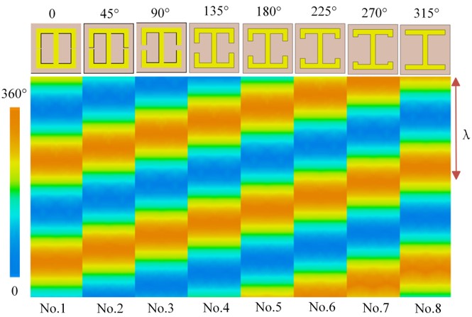
Figure 5: Phase gradient difference of the eight unit cells.

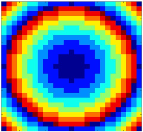
Figure 6: (a) Layout of the metasurface. (b) Phase distributions for electromagnetic wave focusing distance D of 50 mm.
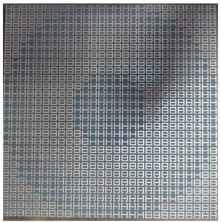
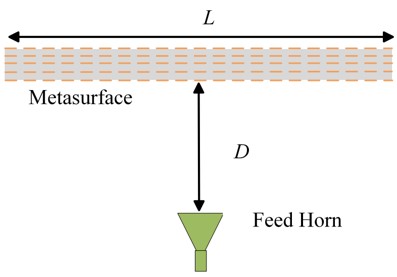
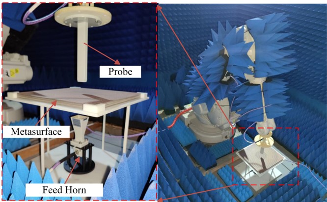
Figure 7: (a) The fabricated metasurface photograph. (b) Experimental test and diagnostics setup.
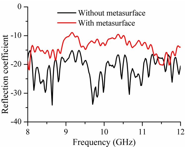
Figure 8: Feed horn measured reflection coefficient with and without metasurface.
The designed metasurface is fabricated based on printed circuit board technology, seen in Fig. 7 (a). The dielectric material is Rogers RO3035, with 2.5 mm thickness and a relative dielectric constant of 3.5. Figure 7 (b) exhibits the photo of the fabricated metasurface lens antenna and its experimental installation in the anechoic chamber. A planar near field test system is used for radiation parameters measurement, which is especially suitable for high gain antenna testing [32–35]. An X-band standard horn antenna is used as the feed source, and the distance between the metasurface and the horn is D 50 mm. The reflection coefficients of the feed horn with and without metasurface are given in Fig. 8, showing that the reflection coefficients are less than 10 dB across the X-band.
Figure 9 shows the simulated 3D radiation patterns at 9 GHz and 11 GHz. The designed metasurface shows a very strong electromagnetic wave focus capability. The gain patterns of the metasurface lens antenna and feed horn are depicted in Fig. 10, both in simulation and measurement. The gain of the feed horn is 11.5 dBi at 9 GHz and 13.5 dBi at 11 GHz. Meanwhile, the metasurface lens antenna displays measured gains of 16.9 dBi at 9 GHz and 19.2 dB at 11 GHz. As a result, a gain enhancement of 5.4 dB and 5.7 dB are achieved at 9 GHz and 11 GHz, respectively. Figure 10 also presents the simulated and measured 2D radiation pattern in the xoz-plane and yoz-plane at 9 GHz and 11 GHz. The tested gains are almost in line with the simulated results, with a difference of 0.45 dB less than the simulation gain at 9 GHz and 0.6 dB less than the simulation gain at 11 GHz. This discrepancy can be attributed to the fabrication tolerance of metasurface and the loss of the printed circuit board. According to [30], the aperture efficiency can be calculated by G/D G/(4PQ/)100%, with P Q 270 mm being the length and width of the lens antenna system, respectively. The measured aperture efficiency at 9 GHz (11 GHz) is about 5.9% (6.7%).
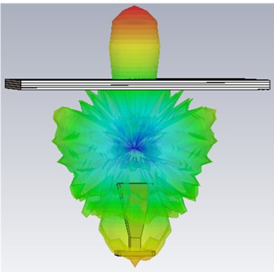
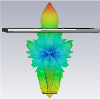
Figure 9: Simulated 3D radiation pattern: (a) 9 GHz and (b) 11 GHz.
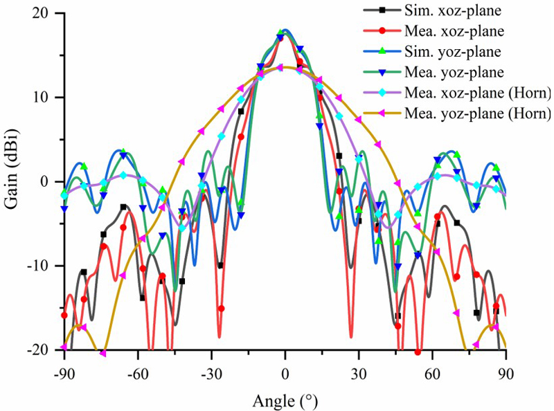
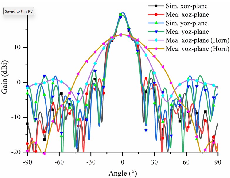
Figure 10: Simulated and measured patterns of the proposed metasurface lens antenna: (a) 9 GHz and (b) 11 GHz.
Table 1: Comparison of the proposed TA with referenced ones
| Ref. | Freq. | 1 dB Gain BW | Unit Transmission Phase | Unit Transmission Amplitude | Profile |
| [11] | 9.4-10.6 | 3.4% | 215 | 0.72 | 0.2 |
| [12] | 11-12.5 | 8.4% | 360 | 0.60 | 0.68 |
| [13] | 11.65-12.3 | 5.4% | 265 | 0.75 | 0.08 |
| [14] | 29 | 7.5% | 360 | 0.71 | 1.0 |
| [15] | 11.3 | 9% | 360 | 0.89 | 0.45 |
| [29] | 9.4-11.2 | 15.5% | 360 | 0.71 | 0.43 |
| This work | 8.8-11.2 | 5.7% | 360 | 0.70 | 0.33 |
The presented design is compared with the referenced antennas, as shown in Table 1. The designed metasurface lens antenna reflects certain advantages in terms of comprehensive performance, such as 1-dB gain bandwidth and profile. For [11, 13], the 1-dB gain bandwidth is only 3.4% and 5.4%, respectively. The proposed metasurface unit cell has the advantage of a low profile (0.33 mm) and a large transmission phase range (360) with a large operating bandwidth (8.8-11.2 GHz). For the unit cell transmission and amplitude, the proposed unit cell has a relative balanced advantage of satisfying 360 phase variety and high amplitude transmission (0.7). Furthermore, the four-layer identical unit cell structure makes the proposed metasurface easily set to apply to other working frequencies.
IV. CONCLUSION
This paper proposes a new type of metasurface for lens antenna applications. This metasurfaces unit cell comprises five metallic layers with split resonant rings positioned back-to-back. The metasurface comprises five metallic layers on a 2.5 mm thick dielectric substrate. The unit cell provides a transmission phase coverage of over 360 with a transmission amplitude of over 70% at the X-band frequency range of 8.8-11.2 GHz. The metasurface has been designed and verified on a 2.5 mm thick dielectric substrate. When an electromagnetic wave from an X-band feed horn is directed towards it, the metasurface focuses the waves within the operating band that covers 8.8 to 11.2 GHz. The measured gain is 16.9 dB at 9 GHz and 19.2 dB at 11 GHz. This represents a gain enhancement of 5.4 dB at 9 GHz and 5.7 dB at 11 GHz. The metasurface provides a 1-dB gain bandwidth (5.7%) from 8.8 to 11.2 GHz. The proposed metasurface is a good reference for engineering applications.
REFERENCES
[1] B. Rana, I.-G. Lee, and I.-P. Hong, “A 44 digitally reconfigurable transmitarray: measurement of radiation patterns,” IEICE Electron. Express, vol. 19, 20210550, 2022.
[2] Y. Zhang, Z. Han, X. Lv, K. Yan, Z. Weng, and Z. Wu, “Novel one-bit digital coding broadband transmits array antenna,” IEICE Electron. Express, vol. 17, 20200195, 2022.
[3] S. Yu, L. Li, and N. Kou, “One-bit digital coding broadband reflectarray based on fuzzy phase control,” IEEE Antennas Wireless Propag. Lett., vol. 16, pp. 1524-1527, 2017.
[4] C. D. Giovampaola and N. Engheta, “Digital metamaterials,” Nat. Mater., vol. 13, pp. 1115-1121, 2014.
[5] T. J. Cui, M. Q. Qi, X. Wan, J. Zhao, and Q. Cheng, “Coding metamaterials, digital metamaterials and programmable metamaterials,” Light Sci. Appl., vol. 3, e218, 2014.
[6] M. A. Al-Jocularly and N. Behdad, “Wideband planar microwave lenses using sub-wavelength spatial phase shifters,” IEEE Trans. Antennas Propag., vol. 59, no. 12, pp. 4542-4552, 2011.
[7] T.-B. Nguyen, N. Kinai, N. Michishita, H. Morishita, T. Miyazaki, and M. Tadokoro, “Dual-polarized metasurface using multi-layer ceramic capacitors for radar cross section reduction,” IEICE Transactions on Communications, vol. E103.B, no. 8, pp. 852-859, 2020.
[8] G. Zhao, T. Liu, J. Jiang, L. Zhao, G.-L. Huang, and W. Lin, “Polarization selective partial reflective decoupling layers for mutual coupling reduction of two closely spaced dual-polarized antennas,” IEEE Transactions on Antennas and Propagation, vol. 70, no. 11, pp. 11205-11210,2022.
[9] W. Yang, S. Chen, Q. Xue, W. Che, G. Shen, and W. Feng, “Novel filtering method based on metasurface antenna and its application for wideband high-gain filtering antenna with low profile,” IEEE Trans. Antennas Propag., vol. 67, no. 3, pp. 1535-1544, 2019.
[10] Y. M. Pan, P. F. Hu, X. Y. Zhang, and S. Y. Zheng, “A low-profile high-gain and wideband filtering antenna with metasurface,” IEEE Trans. Antennas Propag., vol. 64, no. 5, pp. 2010-2016, 2016.
[11] J.-J. Liang, G.-L. Huang, J.-N. Zhao, Z.-J. Gao, and T. Yuan, “Wideband phase gradient metasurface antenna with focused beams,” IEEE Access, vol. 7, pp. 206767-206772, 2019.
[12] X. Zhong, H.-X. Xu, L. Chen, W. Li, H. Wang, and X. Shi, “An FSS-backed broadband phase-shifting surface array with multimode operation,” IEEE Trans. Antennas Propag., vol. 67, no. 9, pp. 5974-5981, 2019.
[13] C. Tian, Y.-Q. Lu, G. Zhao, Y.-C. Jiao, and L.-X. Guo, “Double-layer transmitarray antenna using specially designed substrate,” IEEE Antennas Wireless Propag. Lett., vol. 21, no. 3, pp. 441-445, 2022.
[14] C. G. M. Ryan, M. R. Chaharmir, J. Shaker, J. R. Bray, Y. M. M. Antar, and A. Ittipiboon, “A wideband transmitarray using dual resonant double square rings,” IEEE Trans. Antennas Propag., vol. 58, no. 5, pp. 1486-1493, 2010.
[15] A. H. Abdelrahman, A. Z. Elsherbeni, and F. Yang, “High-gain and broadband transmitarray antenna using triple-layer spiral dipole elements,” IEEE Antennas Wireless Propag. Lett., vol. 13, pp. 1288-1291, 2014.
[16] Q. Luo, S. Gao, M. Sobhy, and X. Yang, “Wideband transmit array with reduced profile,” IEEE Antennas Wireless Propag. Lett., vol. 17, no. 3, pp. 450-453, 2018.
[17] X. Lv, Z. Han, X. Jian, Y. Zhang, and Q. Chen, “A wideband transmit array using triple-layer elements with reduced profile,” IEICE Electron. Express, vol. 17, 20190678, 2020.
[18] C. Tian, Y.-C. Jiao, G. Zhao, and H. Wang, “A wideband transmitarray using triple-layer elements combined with cross slots and double square rings,” IEEE Antennas Wireless Propag. Lett., vol. 16, pp. 1561-1564, 2017.
[19] M. Faenzi, G. Minatti, and S. Maci, “Metasurface antennas: Design and performance,” IEICE Transactions on Communications, vol. E102.B, no. 2, pp. 174-181, 2019.
[20] G.-M. Zhang, J.-S. Hong, and B.-Z. Wang, “A novel pattern reconfigurable wideband slot antenna using PIN diodes,” in International Conference on Microwave and Millimeter Wave Technology,2010.
[21] R. Lian, Z. Tang, and Y. Yin, “Design of a broadband polarization-reconfigurable Fabry-Perot resonator antenna,” IEEE Antennas Wireless Propag. Lett., vol. 17, no. 1, pp. 122-125, 2018.
[22] S.-L. Chen, F. Wei, P.-Y. Qin, Y. Jay Guo, and X. Chen, “A multi-linear polarization reconfigurable unidirectional patch antenna,” IEEE Trans. Antennas Propag., vol. 65, no. 8, pp. 4299-4304, 2017.
[23] W. Lin and H. Wong, “Polarization reconfigurable aperture-fed patch antenna and array,” IEEE Access, vol. 4, pp. 1510-1517, 2016.
[24] A. Bhattacharjee, S. Dwari, and M. K. Mandal, “Polarization-reconfigurable compact monopole antenna with wide effective bandwidth,” IEEE Antennas Wireless Propag. Lett., vol. 18, pp. 1041-1045, 2019.
[25] Y. J. Liu and Y. H. Ge, “Polarization-reconfigurable flat transmitarray based on square frame and crossed dipole elements,” IEICE Transactions on Communications, vol. E100. B, pp. 1904-1910, 2017.
[26] X. Yi, T. Su, X. Li, B. Wu, and L. Yang, “A double-layer wideband transmitarray antenna using two degrees of freedom elements around 20 GHz,” IEEE Trans. Antennas Propag., vol. 67, no. 4, pp. 2798-2802, 2019.
[27] X.-J. Yi, T. Su, B. Wu, J.-Z. Chen, L. Yang, and X. Li, “A double-layer highly efficient and wideband transmitarray antenna,” IEEE Access, vol. 7, pp. 23285-23290, 2019.
[28] C.-H. Lee and J.-H. Lee, “Low profile high-efficiency transmitarray antenna based on hybrid frequency selective surface,” IEICE Transactions on Communications, vol. E104. B, no. 1, pp. 49-54, 2021.
[29] B. Rahmati and H. R. Hassani, “High-efficient wideband slot transmitarray antenna,” IEEE Trans. Antennas Propag., vol. 63, no. 11, pp. 5149-5155, 2015.
[30] T. Cai, G.-M. Wang, X.-L. Fu, J.-G. Liang, and Y.-Q. Zhuang, “High-efficiency metasurface with polarization dependent transmission and reflection properties for both reflectarray and transmit array,” IEEE Trans. Antennas Propag., vol. 66, no. 6, pp. 3219-3224, 2018.
[31] H. Hao, X. Ran, Y. Tang, S. Zheng, and W. Ruan, “A single-layer focusing metasurface based on induced magnetism,” Progress in Electromagnetics Research, vol. 172, pp. 77-88, 2021.
[32] J. Zheng, X. Chen, and Y. Huang, “An effective antenna pattern reconstruction method for planar near-field measurement system,” IEEE Transactions on Instrumentation and Measurement, vol. 71, Art. no. 8005012, 2022.
[33] J. Zheng, C. Pan, Z. Wang, L. Zhang, and X. Chen, “An efficient data reconstruction method for broadband planar near-field measurements based on the field distribution similarity,” IEEE Transactions on Instrumentation and Measurement, vol. 72, Art. no. 1008514, 2023.
[34] J. Tang, X. Meng, X. Chen, R. Chen, Y. Da, S. Zhu, A. Zhang, and M. Yu, “Efficient angle calibration method for peak beam measurements in transmitarray-based compact antenna test range,” IEEE Transactions on Electromagnetic Compatibility, vol. 65, no. 6, pp. 1941-1951,2023.
[35] J. Tang, X. Chen, X. Meng, Z. Wang, Y. Ren, C. Pan, X. Huang, M. Li, and A. A. Kishk, “Compact antenna test range using very small F/D transmitarray based on amplitude modification and phase modulation,” IEEE Transactions on Instrumentation and Measurement, vol. 71, Art. no. 8001614, 2022.
BIOGRAPHIES

Yu Dong completed her masters in Electronic Communication Engineering from the University of Electronic Science and Technology of China, Chengdu, Sichuan Province, in 2009. Currently, she is pursuing a doctoral degree in electronic communication engineering at Sichuan University. Her research focuses on microwave and antenna arrays.

Xing Chen received the M.S. degree in radio physics and the Ph.D. degree in biomedical engineering from Sichuan University, Sichuan, China, in 1999 and 2004, respectively. He is currently a Professor with the College of Electronics and Information Engineering, Sichuan University. His main research interests include antenna and microwave imaging. Dr. Chen is a Senior Member of the Chinese Institute of Electronics.
ACES JOURNAL, Vol. 39, No. 10, 861–867
doi: 10.13052/2024.ACES.J.391003
© 2024 River Publishers