Introducing a 12/10 Induction Switched Reluctance Machine (ISRM) for Electric Powertrains
M. Joodi, M. Abbasian*, and M. Delshad
Department of Electrical Engineering
Isfahan (Khorasgan) Branch, Islamic Azad University, Isfahan, Iran
joodi@khuisf.ac.ir, m.abbasian@khuisf.ac.ir, delshad@khuisf.ac.ir
Submitted On: November 18, 2023; Accepted On: June 9, 2024
ABSTRACT
The induction switched reluctance machine (ISRM) is a novel electric machine that integrates the switched reluctance machine (SRM) with rotor inductive conductors to enhance performance in electric vehicle (EV) powertrain applications. In this topology, the rotor conductors act as a magnetic shield, diverting magnetic flux and preventing magnetic field lines from penetrating the rotor body. By engineering this design, short magnetic flux paths are created in both the stator and rotor of the electric machine. Since its recent introduction, the ISRM represents an emerging technology in the early stages of development. Similar to conventional SRMs, the ISRM can take on various topologies with different stator and rotor pole numbers. Minimizing rotor copper loss is a critical consideration in the ISRM design process. This paper examines two distinct ISRM topologies (12/10 and 12/8), and their characteristics are analyzed using the finite element method. Simulation results, including power density, torque density, efficiency, and copper loss, are presented and compared. Finally, the optimal ISRM topology is proposed for hybrid electric powertrains.
Index Terms: Electric vehicle, electromagnetic induction, reluctance machines, torque.
I. INTRODUCTION
Electric vehicles (EVs) and hybrid electric vehicles (HEVs) have been demonstrated to be an imminent technology and an outstanding alternative to gasoline and diesel vehicles. EVs have an electric motor instead of an internal combustion engine, and the engine size of HEVs is smaller than conventional vehicles. As a result, they generate less emissions and have better fuel economy [1]. Traditionally, batteries on HEVs can only be recharged through regenerative braking or slowing, meaning that most of the work is carried out by the combustion engine [2]. Another breed of HEVs, called PHEVs, are equipped with a dedicated charging socket which enables the batteries to be charged using external charging equipment [3].
Automobile designers and engineers have been working on EVs and HEVs since 1900s, and most car manufacturers have launched their HEV or EV prototypes or even mass-produced them. However, due to the technical challenges and high mass production costs, their popularity in the market has been lower than what expected. EVs and HEVs account for less than 5% of worldwide vehicle production. Therefore, a lot of work still needs to be done. The main challenges that negatively impact the adoption rate of EVs consists of high initial cost, lack of charging stations, and chargingtime [4].
Electric machines employed in HEVs are required to have features including high torque, high power density, high reliability, high efficiency, low level of noise and vibration, and reasonable cost. Permanent magnet synchronous motors (PMSMs) are widely used in the powertrain of EVs and HEVs [5]. Some HEV powertrain systems, such as Toyota Prius, implement two PMSMs for traction and generator application.
PMSM benefits from high torque and power density, but permanent magnet materials employed in this machine are the major source of concern. Permanent magnet materials contain rare earth materials, such as neodymium. In recent years, the rare earth materials price has ramped up and suffered fierce fluctuations [6].
Engineers and researchers have conducted many efforts to eliminate or at least reduce permanent magnet materials from electric machines employed in HEVs and EVs propulsion systems. Induction machines (IMs) are another option that has been used in electric powertrains. For instance, the first models of Tesla EV powertrains were engineered using IMs. Compared to PMSM, IMs have lower efficiency and torque density. This leads more car manufacturers to consider PMSM as the first option for EV and HEV applications [7].
Extensive efforts have been dedicated to the advancement of electric machines that eliminate the need for permanent magnets, focusing on the generation of reluctance torque [8]. One promising alternative for powertrains in EVs and HEVs is the switched reluctance machine (SRM). SRM works on the principle of variable reluctance: the rotor of this motor constantly tries to align through the lowest reluctance lane. The formation of the rotary magnetic field can be done using the circuit of power electronics switching. SRM has no permanent magnet or rare earth materials. It is a robust machine that has better operation at high temperatures and high rotational speeds, compared to PMSM.
Several references have proposed conventional SRM for HEV and EV propulsion systems. Conventional SRM suffers from low torque and high level of noise and vibration [9]. In recent decades, scientists have been working to design and develop new SRM topologies with higher torque density and lower noise and vibration. For instance, a high torque SRM was proposed for HEV powertrain application in [10]. In [11], a bipolar SRM was designed for automotive applications. It was shown that this machine produces higher torque and lower noise and vibration compared to conventional SRM.
Researchers have been working on developing revolutionary SRM topologies to overcome SRM problems. For instance, a short magnetic flux path SRM, named segmental SRM, was proposed by Mecrow [12]. An improved version of this novel machine with single tooth windings was presented in [13]. In 2013, an 80-kw segmental rotor SRM was designed for EV application [14].
Short magnetic flux path SRM is a category of SRMs which benefits from a magnetic flux path that does not circle entire stator and rotor yoke. This leads to lower iron loss, lower noise and vibration, and higher torque density. Segmental SRMs can be designed in different configurations. Some of them have segmental stator and non-segmental rotor, but some other topologies have non-segmental stator and segmentalrotors [15].
Segmental SRMs can generate torque up to 50% more than conventional SRMs with the same volume. The reason is that the magnetic flux lines in segmental SRMs are oriented more in the motional direction. Moreover, the radial forces have lower amplitude, and the machine experiences lower noise and vibration. This is a great achievement in the field of SRM design, but there is an important drawback that prohibits the development of segmental SRMs. The problem is that the rotor or the stator of segmental SRMs is comprised of several ferromagnetic poles which are installed in a non-ferromagnetic housing. This structure hardens the machine production, and particularly prevents achieving a very small and uniform airgap between the stator and the rotor. If the segmental SRM does not benefit from a very small airgap, the phase inductance in the aligned position will not be large enough to produce very high torque levels. In addition, the process of the segmental rotor or stator assembly during mass production of the machine may cause airgap non-uniformity, that leads to unbalanced radial forces. The unbalanced forces are the main source of vibration in the electric machines.
This discussion clarifies that the segmental SRMs are not ideal options to take the place of the conventional SRMs. A new configuration of segmental SRM, called double stator switched reluctance machine (DSSRM) was invented in 2010 [16]. This machine comprises one segmental rotor which is installed between two stators. DSSRM can generate torque two times more than a conventional SRM with the same volume. In addition, this machine has very low noise and vibration level. DSSM has been proposed in several references as a considerable option for EV and HEV powertrains. Double rotor switched reluctance machine (DRSRM) with very high torque density is another novel SRM which was presented in [17].
As discussed above, engineering novel SRM topologies has been a trend over the years. Some researchers have been working to develop optimized versions of conventional SRM in terms of shape optimization or control drive system [18]. Most of these attempts are based on artificial intelligence, genetic algorithm, and neural networks. The objectives used in these optimization algorithms are based on maximum torque density, maximum torque per ampere, and maximum torque per motor loss [19]. In some works, vibration and torque ripple of switched reluctance motors are mitigated through current profile optimization [20].
The induction switched reluctance machine (ISRM) is a novel electric machine that has a conventional structure, and benefits from short magnetic flux path and high torque density [21]. The machine consists of two ferromagnetic parts, the stator and the rotor, which are not segmental (unlike segmental SRMs). The novelty is based on the arrangement of conductors on the rotor which act like a magnetic shield and prevent the magnetic flux entering the rotor poles. This novel topology potentially helps ISRM to generate torque density approximately two times more than conventional SRMs [22]. In addition, the short flux path results in lower copper loss in the machine at high speeds, which is the dominant loss. The results which are comprehensively presented and discussed in [22] confirm that, despite the rotor copper loss due to the rotor windings, the efficiency of ISRM is higher than conventional SRMs.
ISRM can be designed and developed in various stator and rotor pole numbers and phase numbers. Each configuration requires a specific rotor and stator winding topology in terms of winding pitch. In this paper, two different 3-phase ISRM, 12/8 and 12/10, will be considered. The magnetic flux path of each machine is determined, and the copper loss and efficiency of them are calculated using finite element method (FEM). A comprehensive competition between these two ISRMs is performed, and the results are presented.
II. 12/8 INDUCTION SWITCHED RELUCTANCE MACHINE
Various stator and rotor pole numbers can be considered for ISRM. To achieve the best configuration in terms of efficiency and power density, different configurations should be studied and compared. In order to design an ISRM, firstly the number of phases should be considered. Then, based on the stator and rotor winding pitches, the number of rotor and stator poles should be chosen. In this paper, 3-phase ISRMs are considered. As a result, the stator pole numbers should be a multiple of 6. Like conventional SRMs, the simplest 3-phase configuration of ISRM has 6 stator poles and 4 rotor poles.
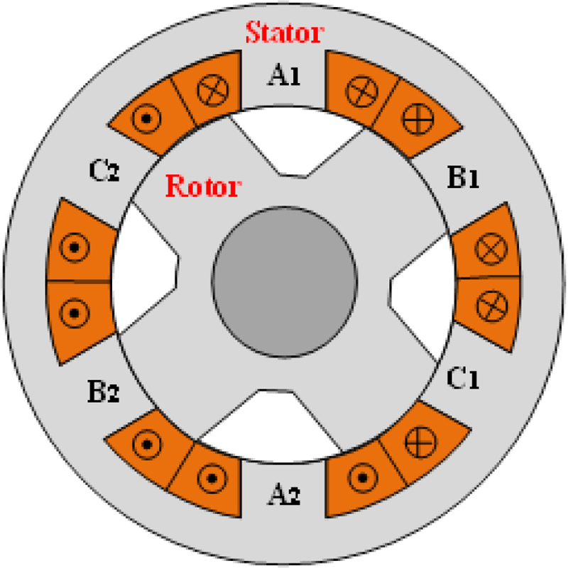
Figure 1: Cross-section of a conventional 6/4 SRM.
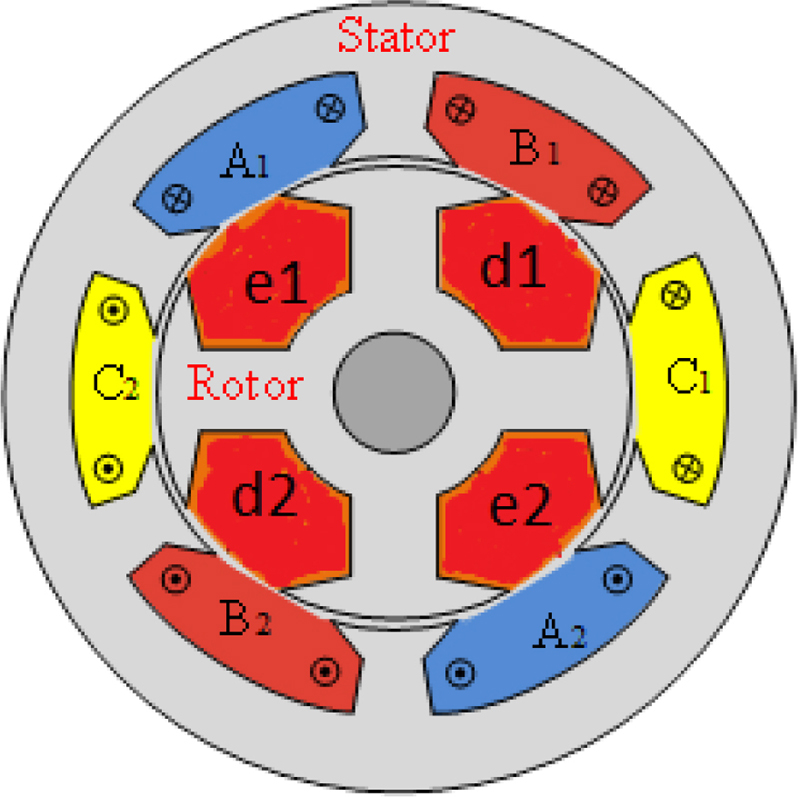
Figure 2: Cross-section of a 6/4 ISRM.
There is an important difference between the stator winding topology of ISRM and conventional SRM. In conventional 6/4 SRM, the phase windings are concentrated and each coil is wound around each stator pole, as shown in Fig. 1. In 6/4 ISRM, the coil span is 180 and the phase windings are full pitch, as shown in Fig. 2. This leads to a considerable end winding, and consequently higher copper loss and higher motor length in 6/4 ISRM, compared to 6/4 SRM. In order to mitigate this drawback of ISRM, other ISRM configurations with smaller end windings should be considered. 12/8 ISRM is a candidate that can be considered for this purpose.
The 12/8 ISRM is a 3-phase ISRM with the stator coil span of 90. This leads to a smaller end winding, because each phase coil is distributed between 4 slots, rather than 2 slots, which is the case in 6/4 ISRM. As a result, the number of conductors which overlap at the end sides of the 12/8 ISRM is half of the 6/4 ISRM. Fortunately, the rotor windings of 12/8 ISRM are concentrated, and this is a merit for 12/8 ISRM. In 6/4 ISRM, the rotor windings are long pitch with a coil span of 180, which increases the final rotor length and rotor copper loss. In 12/8 ISRM, two coils per phase are connected in series to form each phase. For instance, aa and aa form phase A. This is also the case for phase B and phase C. The winding strategy of the rotor is completely different. On the rotor, one isolated short-circuited concentrated winding is wound around each rotor pole (ff, gg, hh, gg, hh, ii, jj, hh). Like conventional SRM, pulsed DC is required to excite each phase.
In [21], a 12/8 ISRM was designed and analyzed and compared with a conventional 12/8 SRM. The results confirmed that the 12/8 ISM has higher torque density and efficiency, compared to conventional 12/8 SRM.
Table 1: Characteristics of the ISRMs
| Stator Outer Radius | 115 mm |
|---|---|
| Stack length | 90 mm |
| Airgap | 0.5 mm |
| Number of stator poles | 12 |
| Number of rotor poles | 8 or 10 |
| Turn number of stator and rotor windings | 40 |
| Rated current | 200 A |
| Maximum current density of windings | 20 A/mm |
| Motor core material | M19 |
| Rated power | 80 kW |
| Slot fill factor | 60% |
| Motor length (12/8) | 209 mm |
| Motor length (12/10) | 152 mm |
| Cooling method | Oil spray |
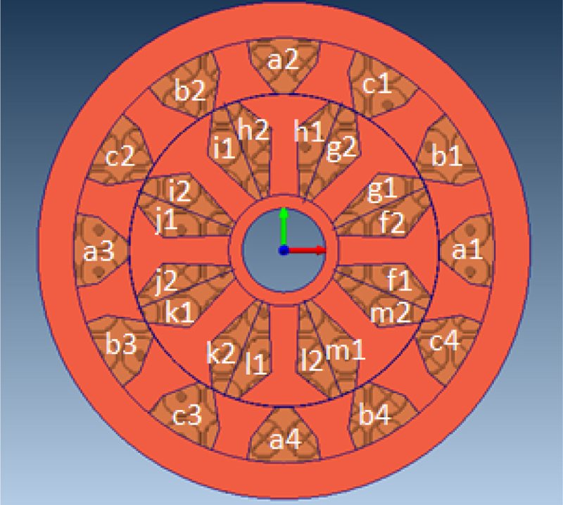
Figure 3: Cross-section of a 12/8 ISRM.
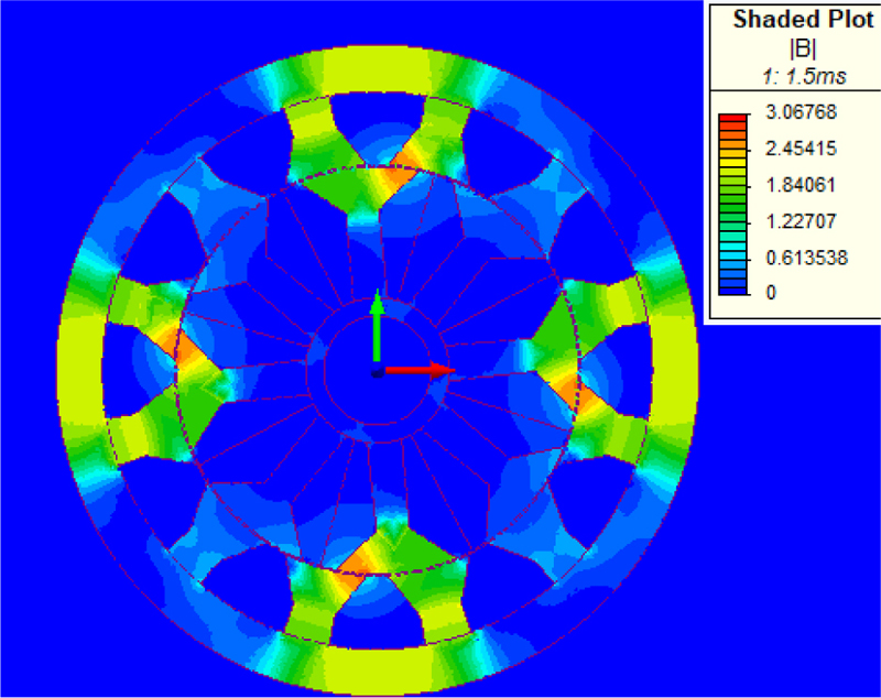
Figure 4: Flux distribution in 12/8 ISRM.
In order to investigate the flux path and output characteristics of 12/8 ISRM, a 12/8 ISRM with the parameters presented in Table 1 is considered and simulated. The machine configuration is shown in Fig. 3. First, the flux path of the machine is studied. Due to the effect of induction phenomenon on the rotor windings, transient FEM simulation must be performed to analyze the performance of ISRM. For this purpose, one phase is excited with a constant current for 15 degrees, from unaligned position to aligned position, while the rotor is running at a constant speed of 1500 rpm. The magnetic flux path of the machine is extracted when the rotor is on the verge of full alignment, as shown in Fig. 4. Figure 5 shows the magnetic flux path and the current density of the stator and rotor windings. It is clear that a short flux path is created around each excited winding of phase A. The induced currents in the rotor windings are also observable in Fig. 5. As shown in Fig. 5, the current is induced in all of the rotor coils, which leads to high level of rotor copper loss. This can increase the rotor ohmic loss and the rotor temperature, which hardens the rotor cooling process.
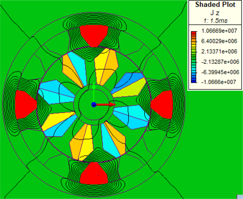
Figure 5: Current density in 12/8 ISRM.
III. 12/10 INDUCTION SWITCHED RELUCTANCE MACHINE
Due to the presence of conductors on the rotor of ISRM, a magnetic short flux path is created in the machine and, hence, high torque is achieved. However, rotor conductors will be a major source of copper loss and heat in ISRM. Direct liquid cooling systems, such as oil spray cooling (which is used in the Toyota Prius), can cool down the internal parts of the machine, but designing an ISRM with lower rotor copper loss can alleviate the need for such a cooling system and increase the efficiency of the machine. In addition, in the 12/8 ISRM the stator windings are long pitch with a coil span of 90, which increases the final stator length and stator copper loss. This urges researchers to design an ISRM stator with short pitch windings. In conclusion, the best ISRM has short pitch windings on both stator and rotor. This brings up the subject of an ISRM with less copper loss and length.
In this section a 12/10 ISRM is introduced. Its configuration is shown in Fig. 6. This electric machine benefits from short pitch concentrated windings on the rotor and stator. There are two types of stator poles with different widths in this machine. The width of the thick poles is two times greater than the width of the thin poles. The stator coils are wound around thick poles, as shown in Fig. 6. This machine has three phases: phase A is comprised of aaaa, phase B is comprised of bbbb, and phase C is comprised of cccc. On the rotor side, the width of all poles is the same, and one coil is wound around each rotor pole. It should be mentioned that all rotor windings are separately short circuited and are not connected together. The result is that there are 10 isolated short-circuited windings on the rotor (ff, gg, hh, ii, jj, kk, ll, mm, nn, oo).
A 12/10 ISRM with the characteristics presented in Table 1 is analyzed and compared with the 12/8 ISRM. The stator outer diameter, the stator stack length, and the slot fill factor of the 12/10 ISRM is the same as the 12/8 ISRM which was analyzed in the previous section. The final motor length of the 12/10 ISRM is 27% less than the 12/8 ISRM.
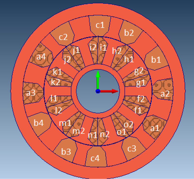
Figure 6: Cross-section of a 3-phase 12/8 ISRM.
A transient finite element model of the machine is created and solved in Magnet Infolytica. In this simulation, phase A is excited with a constant current, while the rotor is running with the speed of 1500 rpm from unalignment to alignment position. The magnetic flux path of the machine is extracted and drawn as shown in Fig. 7 when the rotor is on the verge of full alignment. Moreover, Fig. 8 shows the magnetic flux path and the current density of the stator and rotor windings. The figures show that a short flux path is created around each excited winding of phase A. The induced currents in the rotor windings are shown in Fig. 8. Dissimilar to 12/8 ISRM, the current is not induced in all of the rotor coils of 12/10 ISRM. This leads to a lower level of rotor copper loss, compared to 12/8 ISRM. This will be fully considered and investigated in the next section of this paper.
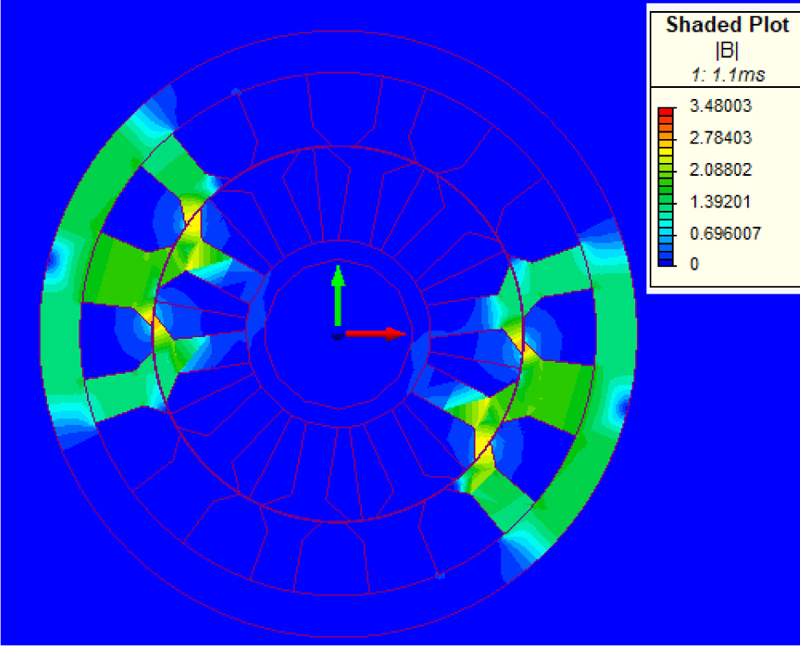
Figure 7: Flux distribution in 12/10 ISRM.

Figure 8: Current density in 12/10 ISRM.
IV. COMPARISION OF 12/8 ISRM AND 12/10 ISRM
Rotor windings play a very important role in the correct operation of ISRM by preventing the flux line from entering the rotor yoke of the machine and creating a short magnetic flux path. This phenomenon is based on the Faraday law of induction and Lenz law. This leads to induced electric current in the rotor windings, which is a source of copper loss and heat in the rotor of the ISRM. Rotor copper loss is a crucial aspect of ISRM that must be considered in the optimum design of the machine.
Designing an ISRM with maximum torque density and minimum possible rotor loss is a key issue in the applicability of this novel machine. In this section, using finite element analysis, the torque capability of the 12/8 ISRM and 12/10 ISRM, along with the induced current in the rotor windings of the machines, are studied and compared. In these simulations one phase of the machines is excited by a constant current, while the rotor is running from unaligned position to aligned position, with a constant speed of 1500 rpm.
After completing the simulation, the results are displayed. Firstly, phase A of the machines is excited with a constant current 0f 100 A. The output torque of the two machines is calculated and presented in Fig. 9. The simulation is repeated for different currents (from 0 A to 200 A) at a speed of 1500 rpm, and the average output torque is calculated and presented in Fig. 10. Results show that the output torque of the 12/10 ISRM is higher than the output torque of the 12/8 ISRM, especially at higher phase currents. For instance, at the current phase of 200 A, the average torque of 12/10 ISRM is 14% higher than the average torque of 12/8 ISRM.
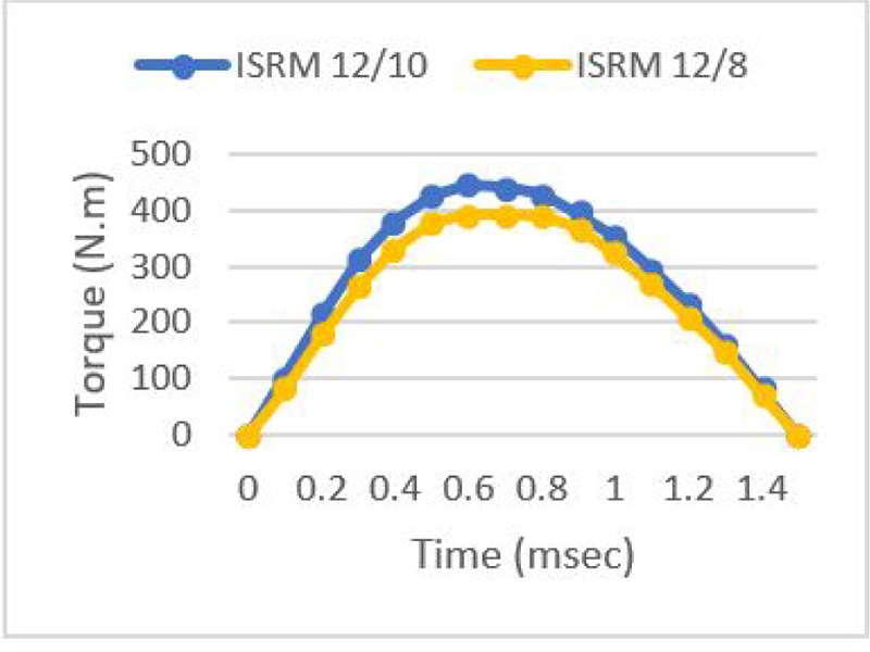
Figure 9: Torque profile of the 12/10 ISRM compared to torque profile of the 12/8 ISRM.
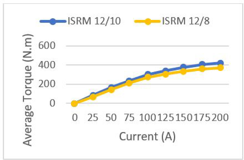
Figure 10: Average torque of the 12/10 ISRM compared to average torque of the 12/8 ISRM.
As mentioned before, the 12/10 ISRM benefits from concentrated windings which are coiled around the stator poles. As shown in Fig. 6, there are two types of stator poles in terms of thickness, and the windings are placed around the thick stator poles. This winding strategy leads to a smaller end winding, compared to 12/8 ISRM. As a result, the final motor length and the volume of 12/10 is less than 12/8 ISRM. The stack length of the 12/8 ISRM and the 12/10 ISRM are the same, and equal to 90 mm. Considering the end windings, the final motor length of the 12/8 ISRM is 209 cm, while the final motor length of the 12/10 ISRM is 152 cm. As a result, the volume of the 12/8 ISRM is 36% higher than the volume of the 12/10 ISRM.
Using these resultant data, the average torque per volume of the 12/8 ISRM and the 12/10 ISRM for different currents (from 0 A to 200 A) is calculated and the results are presented in Fig. 11. The results show that, at high currents, the torque density of the 12/10 ISRM is about 50% higher than the torque density of the 12/8 ISRM.
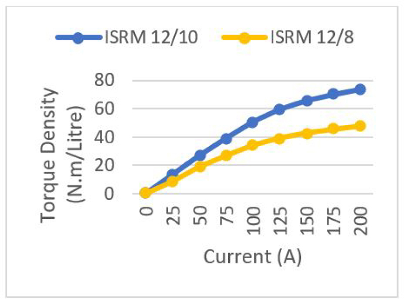
Figure 11: Torque density of the 12/10 ISRM compared to torque density of the 12/8 ISRM.
Rotor copper loss is a crucial aspect of ISRM that should be studied in the optimum design of the machine. In this section, using finite element analysis, the induced current in the rotor windings of the 12/8 ISRM and the 12/10 ISRM is calculated and presented. In these simulations, the rotor is running from unalignment to alignment position with a speed of 1500 rpm, and the phases are excited by the constant current of 70 A. Figure 12 shows the induced current in the four rotor windings of 12/8 ISRM (f to i, see Fig. 3). The four other rotor windings of the 12/8 ISRM (j to m) have the same current as Fig. 12. In addition, the induced current in the five rotor windings of 12/10 ISRM (f to j, see Fig. 6) is shown in Fig. 13. The five other rotor windings of the 12/10 ISRM (k to o) have the same shape as Fig. 13, but with negative values.
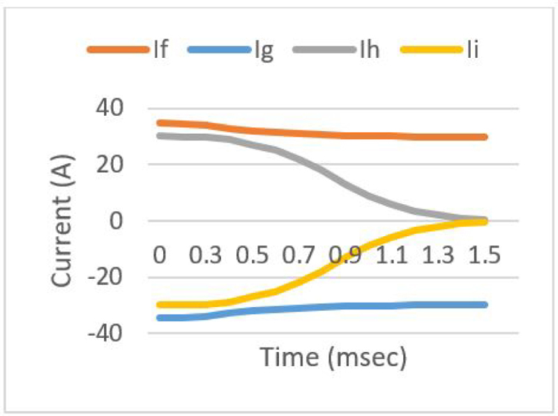
Figure 12: Rotor winding currents of the 12/8 ISRM.
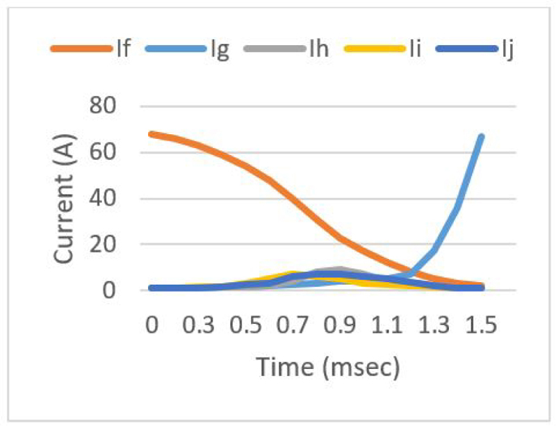
Figure 13: Rotor winding currents of the 12/10 ISRM.
For each machine, the simulation is redone for different phase currents, and the rotor winding currents are extracted. Using these data, the total machine copper loss is calculated in different output powers and the results are presented in Fig. 14. The results confirm that the 12/10 ISRM has lower copper loss, compared to the 12/8 ISRM. This is an important point, specially at high power where copper loss plays an important negative role in appropriate operation and efficiency of the machine. Designing an ISRM with a lower level of copper loss is a significant achievement which can boost the efficiency of the machine. The efficiency of the 12/10 ISRM and the 12/8 ISRM is calculated in different powers, and the results are presented in Fig. 15. The results show that 12/10 ISRM enjoys higher efficiency, which is an important merit for electric powertrain systems.
In ISRMs, similar to SRMs, the stator phases are excited by sequences of DC voltage pulses. These pulses create a magnetic field that interacts with the rotor windings. This interaction not only induces a motional EMF due to the relative motion between the stator and rotor but also a transformer EMF resulting from the changing magnetic field linked with the rotor coils. Unfortunately, it is not feasible to separately quantify the transformer EMF and motional EMF using FEM simulations. The primary challenge lies in the complex nature of the problem and the mutual interactions between these two EMFs. Both EMFs are inherently interlinked, and their combined effect influences the overall performance of the ISRMs. Given the intertwined nature of transformer and motional EMFs, the induced currents in the rotor coils are a result of both phenomena. These currents contribute to Joule losses.
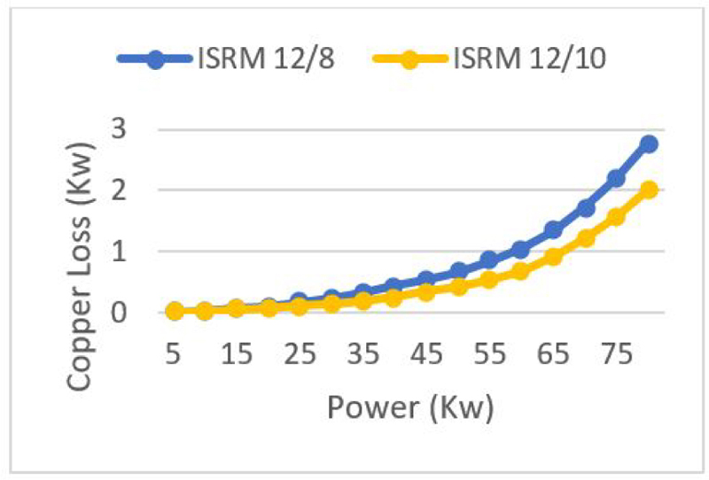
Figure 14: Copper loss of the 12/10 ISRM compared to copper loss of the 12/8 ISRM.
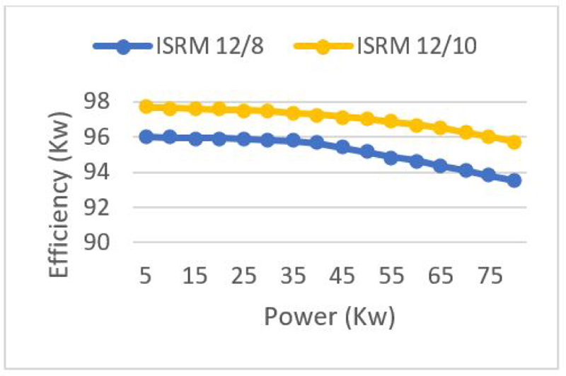
Figure 15: Efficiency of the 12/10 ISRM compared to efficiency of the 12/8 ISRM.
Although it is challenging to separate the individual contributions of transformer and motional EMFs, we expect that the transformer-induced currents might have a more significant impact at lower speeds where the rate of change of the magnetic field is higher. Conversely, motional-induced currents could dominate at higher speeds due to increased rotor movement. Understanding the balance between these losses will help in optimizing the design and control strategies for ISRMs, ultimately improving their efficiency.
V. CONCLUSIONS
In this paper, a 12/10 induction switched reluctance machine (ISRM), was introduced for electric powertrains. In this topology, the rotor windings create a magnetic shield, and divert the magnetic flux and prevent the magnetic field lines from passing into the rotor body. As a result, a short magnetic flux path is created around each excited phase of the machine. In order to evaluate the capability of the 12/10 ISRM, it was compared with a 12/8 ISRM which has been presented in previous research works. The characteristics of the 12/10 ISRM and the 12/8 ISRM, including torque profile, average torque, torque density, rotor currents, copper loss, and efficiency, were extracted using FEM analysis. Simulation results for both machines were presented and compared. Results confirm that the 12/10 ISRM has more torque density and efficiency, compared to the 12/8 ISRM. Moreover, copper loss of the 12/10 ISRM is less than copper loss of the 12/8 ISRM, which alleviates the cooling system of the electric machine.
REFERENCES
[1] L. Liu, Y. Huang, M. Zhao, and Y. Ruan, “Parametric modeling and optimization of switched reluctance motor for EV,” Applied Computational Electromagnetic Society (ACES) Journal, vol. 37, no. 9, pp. 948-958, 2022.
[2] H. Tu, H. Feng, S. Srdic, and S. Lukic, “Extreme fast charging of electric vehicles: A technology overview,” IEEE Trans. Transport. Electrific., vol. 5, no. 4, pp. 861-878, Dec. 2019.
[3] M. Yilmaz and P. T. Krein, “Review of battery charger topologies charging power levels and infrastructure for plug-in electric and hybrid vehicles,” IEEE Trans. Power Electron., vol. 28, no. 5, pp. 2151-2169, May 2013.
[4] M. Popescu, J. Goss, D. A. Staton, D. Hawkins, Y. C. Chong, and A. Boglietti, “Electrical vehicles: Practical solutions for power traction motor systems,” IEEE Trans. Ind. Appl., vol. 54, no. 3, pp. 2751-2762, May/June 2018.
[5] E. Ayciecek, N. Bekiroglu, I. Senol, and Y. Oner, “Rotor configuration for cogging torque minimization of open-slot axial flux permanent magnet synchronous motors,” Applied Computational Electromagnetic Society (ACES) Journal, vol. 30, no. 4, 2015.
[6] G. Pellegrino, A. Vagati, P. Guglielmi, and B. Boazzo, “Performance comparison between surface-mounted and interior PM motor drives for electric vehicle application,” IEEE Trans. Ind. Electron., vol. 59, no. 2, pp. 803-811, Feb. 2012.
[7] X. Sun, Z. Shi, G. Lei, Y. Guo, and J. Zhu, “Analysis and design optimization of a permanent magnet synchronous motor for a campus patrol electric vehicle,” IEEE Trans. Veh. Technol, vol. 68, no. 11, pp. 10535-10544, Nov. 2019.
[8] B. Khan, F. Khan, W. Ullah, M. Umair, and S. Hussain, “Slot filling factor calculation and electromagnetic performance of single phase electrically excited flux switching motors,” Applied Computational Electromagnetic Society (ACES) Journal, vol. 35, no. 8, pp. 922-928, 2020.
[9] M. Abdalmagid, E. Sayed, M. Bakr, and A. Emadi, “Geometry and topology optimization of switched reluctance machine: A review,” IEEE Access, vol. 10, pp. 5141-5170, Jan. 2022.
[10] Z. Yang and F. Shang, “Development of a rare-earth-free SR motor with high torque density for hybrid vehicles,” IEEE Trans. Energy Convers., vol. 30, no. 3, pp. 132-143, Mar. 2015.
[11] C. S. Edrington, M. Krishnamurthy, and B. Fahimi, “Bipolar switched reluctance machines: A novel solution for automotive applications,” IEEE Trans. Veh. Technol., vol. 54, no. 3, pp. 795-808, May 2005.
[12] B. C. Mecrow, J. W. Finch, E. A. El-Kharashi, and A. G. Jack, “Switched reluctance motors with segmental rotors,” IEE Proc. Elect. Power Appl., vol. 149, no. 4, pp. 245-254, July 2002.
[13] B. C. Mecrow, J. W. Finch, and A. G. Jack, “Segmental rotor switched reluctance motors with single-tooth windings,” IEE Proc. Elect. Power Appl., vol. 150, no. 5, pp. 591-599, Sep. 2003.
[14] J. D. Widmer, R. Martin, and B. C. Mecrow, “Optimization of an 80-kW segmental rotor switched reluctance machine for automotive traction,” Proc. IEMDC, pp. 427-433, July 2013.
[15] Emine Bostanci, Mehdi Moallem, Amir Parsapour, and Babak Fahimi, “Opportunities and challenges of switched reluctance motor drives for electric propulsion: A comparative study,” IEEE Trans. Transportation Electrification., vol. 3, no. 1, pp. 58- 75, Mar. 2017.
[16] M. Abbasian, M. Moallem, and B. Fahmi, “Double stator switched reluctance motors: Fundamentals and magnetic force analysis,” IEEE Trans. Energy Convers., vol. 25, no. 3, pp. 589-597, Dec. 2010.
[17] T. Guo, T. Shofield, and A. Emadi, “Double segmented rotor switched reluctance machine with shared stator back-iron for magnetic flux passage,” IEEE Trans. Energy Convers., vol. 31, no. 4, pp. 1278-1286, Dec. 2016.
[18] S. Li, S. Zhang, T. G. Habetler, and R. G. Harley, “Modeling, design optimization, and applications of switched reluctance machines: A review,” IEEE Trans. Ind. Appl., vol. 55, no. 3, pp. 2660-2681, May 2019.
[19] A. Bentounsi, F. Rebahi, and R. E. H. Bouchekara, “Multi-objective optimization design of 8/6 switched reluctance motor using GA and PSO algorithms,” J. Electr. Eng. Technol., vol. 15, no. 4, pp. 168-175, 2015.
[20] C. Ma, L. Qu, R. Mitra, P. Pramod, and R. Islam, “Vibration and torque ripple reduction of switched reluctance motors through current profile optimization,” in Proc. IEEE Appl. Power Electron. Conf. Expo. (APEC), pp. 3279-3285, Mar. 2016.
[21] M. Abbasian, “Induction switched reluctance motor,” U.S. Patent, US20170370296A1, June 30, 2020.
[22] M. Azamian, M. Abbasian, and D. Gerling “Preliminary evaluation of induction switched reluctance motor for electric vehicle application,” IEEE Access, May 30, 2021.
BIOGRAPHIES

Mohammad Joodi was born in Maragheh, Iran, in 1976. He received the bachelor’s degree and M.Sc. Degree in Electrical Engineering from IAU University, Tabriz, Iran, in 2007 and 2014, respectively. From 2016, he has been a PhD student at IAU University, Khorasgan, Isfahan, Iran.
Mohammadali Abbasian received the bachelor’s degree, M.Sc. degree, and Ph.D. degree in Electrical Engineering from Isfahan University of Technology. He was with Renewable Energies and Vehicular Technologies, The University of Texas at Arlington, Arlington, Texas, USA, as Ph.D. exchange student. From 2017 to 2018, he was with the Bundeswehr University, Munich, Germany, as a research scientist. He was an assistant professor at the IAU University, Khorasgan, Isfahn, Iran.

Majid Delshad was born in Isfahan, Iran, in 1979. He received the B.S and M.S degrees in electrical engineering in 2001 and 2004 from Kashan University and Isfahan University of Technology, Iran, respectively. He received the Ph.D. degree in electrical engineering in Isfahan University of Technology. He is associate professor in Isfahan (Khorasgan) Branch, IAU. His research interest includes soft switching techniques in DC-DC converters and current-fed converters.
ACES JOURNAL, Vol. 39, No. 5, 452–460
doi: 10.13052/2024.ACES.J.390509
© 2024 River Publishers