Research on the Composite Electromagnetic Scattering of Rough Surface and Buried Target Based on G-PILE
Juan Zhao
Yichun University
School of Mathematics and Computer Science, Yichun, Jiangxi 336000, China
zj_ycxy@126.com
Submitted On: November 21, 2023; Accepted On: May 9, 2025
ABSTRACT
This article proposes a G-PILE (Generalized Propagation Inside Layer Expansion) algorithm for solving the composite electromagnetic scattering of large-scale dielectric rough surfaces and buried dielectric targets. Firstly, the EFIE (Electric Field Integral Equation) is established, and the traditional PILE algorithm is improved to extend its application to studying the composite scattering characteristics of targets under rough surfaces. In the iterative process, the BMIA/CAG (Banded Matrix Iterative Approach Canonical Grid) is introduced to solve the electromagnetic scattering of the rough surface itself, ultimately reducing the complexity of the algorithm to and achieving acceleration. Meanwhile, a conical incident wave is introduced to reduce the error caused by rough surface truncation. To verify the accuracy of G-PILE, the scattering characteristics of a dielectric cylinder buried under a dielectric rough surface are calculated and compared with existing algorithms. The effectiveness of G-PILE is demonstrated in several aspects. Results show that the algorithm gets excellent performance in accuracy and computation efficiency. Finally, the composite electromagnetic scattering depending on different target parameters is studied. These results are of great significance for understanding and predicting the interaction between rough ground and targets as well as the changes in scattering coefficients.
Index Terms: Dielectric, electromagnetics, generalized propagation inside layer expansion, rough surface, scattering coefficient, target.
I. INTRODUCTION
The study of the composite electromagnetic scattering characteristics [1–7] of targets in a rough sea surface background is of great significance in both civilian and defense applications. Numerical algorithms [8–12] can more accurately simulate and predict the scattering characteristics of rough surfaces and objects. This accuracy is important for practical applications, as it enables us to better understand defensing and tackling real-world problems. For example, in military applications, precise scattering models can help us more accurately locate and track targets; in archaeological applications, precise scattering models facilitate more accurate detection and analysis of underground sites.
In addition to the study of the composite electromagnetic scattering characteristics of targets, the study of the composite scattering characteristics of buried targets is also of great significance [13–19]. For example, in defense, the detection of land mines and hidden targets underground is helpful for strategic decision making. In the archaeology field, the detection of underground sites can reveal the development and remains of historical civilizations. These applications require in-depth research on rough surfaces and targets.
Ishimaru et al. [20] proposed analytical methods for calculating the microrough surface of rough surfaces and the underlying targets. However, the application of analytical methods is limited by the parameters of the rough surface, their application range is relatively narrow, and calculation accuracy is often not high [21–28]. In contrast, numerical algorithms have greater flexibility and higher accuracy. Numerical algorithms can handle various composite rough surface and target models, which can be simulated and verified by computers.
Many scholars have conducted in-depth research on the electromagnetic scattering characteristics of the rough surface and the target. Sami et al. [8] studied the 3D scattering problem of PEC targets buried beneath rough dielectric surfaces. An efficient PILE-ACA (algebraic adaptive cross approximation) algorithm was proposed, and the mixed KA (Kirchhoff approximation)-EFIE formulation was used to extend the solution method of electromagnetic inverse problems, enabling effective simulation and analysis of 3D scattering problems. Mahariq et al. [9] investigated application of the PML (Perfectly Matched Layer) method in the context of SEM (spectral element method) in two-dimensional (2D) frequency domain scattering problems. By using the free space Green’s function as the building block of the scattering field, this method was extended to the analysis of SEM accuracy in large-scale object scattering. The results indicated that SEM can achieve high accuracy and demonstrated the successful applicability of PML in electromagnetic scattering problems. On the basis of maintaining the same measurement error, [10] compared SEM, FDM (finite difference method), and FEM (finite element method), mainly by studying the accuracy in 1D and 2D boundary value problems and demonstrating the high accuracy of SEM [23]. Kizilay and Yucedag [11] studied the TM wave scattering problem of conducting targets buried in a two-layered lossy medium, while [12] studied the scattering problem of targets in 3D littoral and surf-zone environments with multi-layered elastic sediments. The authors used an interior transmission formulation to more accurately describe the propagation of waves between the sediment and the target. They proposed a new numerical method that combined the finite element and finite difference methods to better handle complex boundary conditions and multi-layered structures. Additionally, the authors considered the elastic properties of the sediment to more accurately simulate wave propagation and scattering in the sediment.
In order to improve the speed of obtaining the electromagnetic scattering characteristics of a buried target under a randomly rough surface with large electrical dimensions, this paper proposes a G-PILE acceleration algorithm. The traditional PILE algorithm is a fast numerical algorithm for calculating the scattering of layered rough surfaces. This paper generalizes the standard PILE algorithm to be applicable to studying the composite scattering characteristics of targets below rough surfaces (G-PILE). To enable the algorithm to be applicable to large rough surfaces, the BMIA/CAG (Banded Matrix Iterative Approach Canonical Grid) algorithm is adopted to accelerate the algorithm. The acceleration algorithm solves the unknown variable . Based on this algorithm, this paper also studies the interaction between the target and the rough surface, then analyzes the characteristics of the rough surface and the target.
II. ELECTROMAGNETIC SCATTERING MODEL
A. Electric Field Integral Equation (EFIE)
A schematic diagram of the target and rough surface is shown in Fig. 1, where the rough surface is denoted S. Above the rough surface is free space with permittivity and permeability denoted by and , respectively. It has a medium space with permittivity and permeability denoted by and , respectively. The target is buried below the rough surface, with its surface contour denoted by S and a depth of D. The target has permittivity and permeability denoted by and , respectively. Throughout the region, the incident field is denoted by . The total fields in the free space, medium space, and target are denoted by , , and , respectively, which can be collectively represented by , with subscript i representing different spaces.
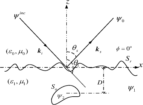
Figure 1: Schematic of rough surface (S) and target (S).
When spot r approaches the rough surface and the target surface, the following boundary integral equations and boundary conditions apply.
for
| (1) | |
| (2) | |
| (3) | |
| (4) |
For :
| (5) |
| (6) | |
| (7) | |
| (8) |
where , for TE incident wave, and , for TM incident wave. represents the Green function of each space, which can be expressed as:
| (9) | ||
| (10) |
B. G-PILE (Generalized Propagation Inside Layer Expansion) algorithm
Using the method of moments based on pulse basis functions, we can discretize the boundary integral equation into the following matrix equation:
| (11) |
In this equation, Z is the impedance matrix, I is the unknown vector to be solved, and V is the excitation vector. The matrix equation can be further expressed as:
| (12) |
where the excitation vector contains two main components. The first is the rough surface excitation vector , which has an expression of (It is represented here as a transposed matrix.) The second is the target excitation vector , which has a value of 0 because the target is not directly illuminated by the incident wave.
Similarly, the unknown vector consists of two parts: the unknown vector of the rough surface and the unknown vector of the target. These two parts can be represented as a transposed matrix
| (13) | ||
| (14) |
The unknown variables to be solved are , , , and , and can be obtained by the following matrix equation:
| (15) |
The key to solving this equation lies in the appropriate treatment of the impedance matrix Z. According to [29], Z can be divided into four parts, namely , , , and . Specifically, represents the impedance matrix of the rough surface, which reflects the characteristics of the rough surface. is the impedance matrix of the target, representing the characteristics of the target. and represent the impedance matrix of the interaction between the rough surface and the target, which reflects the interaction between the two. These four parts taken together constitute the impedance matrix Z. They satisfy the following relationship:
| (16) | |
| (17) | |
| (18) |
Combining (15-18),we get:
| (19) |
where:
| (20) | |
| (21) |
I is the identity matrix. If the characteristic matrix is defined then, according to the above formulas, the following statement holds:
| (22) |
This equation will be difficult to calculate without truncating the order n of the matrix. Therefore, we define a truncation order T, and the truncated unknown vector can be expressed as:
| (23) | ||
| (24) |
The number of sampling points for rough surfaces is usually much larger than that for targets, where the increase in unknown quantities makes the calculation more difficult. Therefore, the key to solving the above process lies in finding the inverse of matrix (whose computational complexity is ). To solve this problem, we construct a matrix equation , which transforms the solution of into the solution of N. In this matrix equation, is the impedance matrix of the rough surface itself, so the solution process of this matrix is equivalent to the solution problem of the dielectric rough surface. We use the BMIA/CAG algorithm as an acceleration algorithm to calculate this matrix, which has low computational complexity, simple relative principles, and is easy to implement. By employing this method, we can effectively accelerate the calculation of dielectric rough surfaces.
The details of BMIA/CAG can be found in [30], which mainly introduces the basic principles and main ideas for accelerated computation. During the iterative solution of , the repeated calculations of consume a large amount of computer memory and have low computational efficiency. Therefore, it is essential to take adequate measures to deal with and accelerate it. The advantages of BMIA/CAG are reflected in this processing and acceleration.
Firstly, we define the strong-weak correlation distance R and partition into a strongly correlated impedance matrix (banded matrix) and a weakly correlated impedance matrix (the remaining part outside the strongly correlated impedance matrix). In this way, the original impedance matrix equation can be transformed into:
| (25) |
In practical calculations, due to the small value of R, we can directly calculate the strongly correlated impedance matrix using the method of moments. For the weakly correlated impedance matrix, due to its high computational cost, we cannot directly calculate it. Therefore, we adopt the CAG method to deal with it, which is to expand the weak matrix in the x-direction using the Taylor series, then represent the multiplication of the weak matrix and column vector as the multiplication of several terms of Toeplitz matrix and column vector. Next, we use FFT to calculate the matrix vector product. The final computational complexity is . Only needs to be solved, greatly reducing the computer memory requirements.
In order to apply numerical algorithms, the calculated region of the rough surface is limited to a certain range. For 2D scattering problems, in order to limit the rough surface to L, it is artificially stipulated that the surface current is zero when . At this point, the surface current will have a sudden change at . If a plane wave is used, then artificial reflections will occur at the two ends. To avoid the error caused by truncation [31], we choose the incident wave to be a conical wave. The widely used Thorsos conical wave can well satisfy the Helmholtz wave equation. Its expression is:
| (26) | ||
| (27) | ||
| (28) |
where g represents the width of the cone, which determines the range of incident wave width and rough surface length. The value of rough surface length is directly related to the efficiency and accuracy of numerical calculation. A larger rough surface value can better reflect the average scattering characteristics of the rough surface, thereby improving the accuracy of numerical calculation. However, this also requires more storage space and calculation time. Therefore, in choosing g, we need to balance the accuracy of the calculation results and the calculation efficiency. Usually, the value range of g can be determined by:
| (29) |
Following the above calculation steps, we can obtain specific values of the scattering field and scattering coefficient [29]:
| (30) | |
| (31) |
Through the detailed description of this process, we can better understand and more accurately describe the scattering phenomenon. In order to ensure the accuracy and rigor of this paper, we will analyze these results in detail in subsequent sections and explore their possible applications and implications.
III. ALGORITHM VALIDITY VERIFICATION
A. Verification of rough surface field results
Firstly, the effectiveness of the algorithm for calculating the total field of a rough surface was studied. The scattering field of the rough surface at different truncation orders Tr was calculated and presented in Fig. 2, as shown by the black and blue lines. The red line represents the results of strict application of the LU decomposition method under the same conditions, which is stable, and is used to verify the algorithm in this article. The relevant parameters are: rough surface length , number of unknowns N=500, root mean square height , correlation length , lower medium relative permittivity . The buried target is a cylinder, which is horizontally placed below the rough surface with depth , radius , and number of unknowns N=50. The relative dielectric constant is . The incident angle is , and the beam width is .
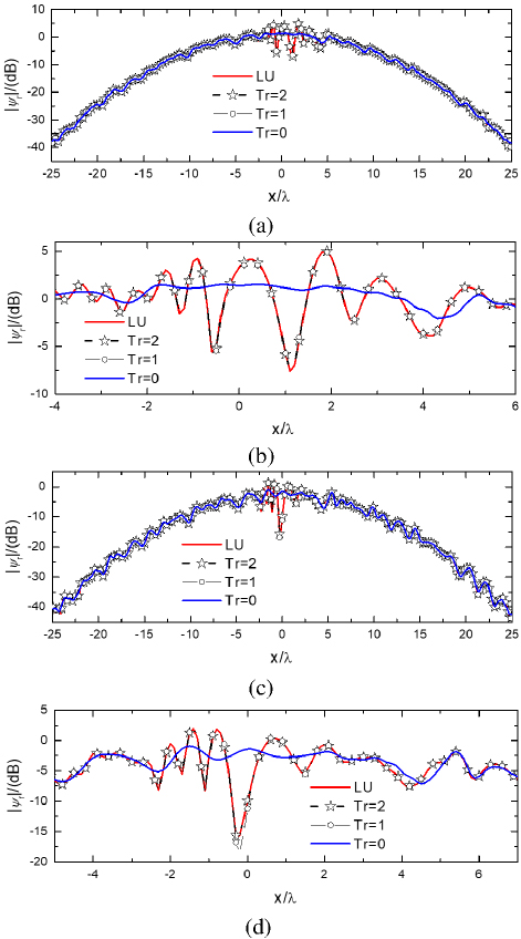
Figure 2: Verification of rough surface field results. (a) TM incident wave, (b) enlarged view of the area within (-4,6) of (a), (c) TE incident wave, and (d) enlarged view of the area within (-5,7) of (c).
From Figs. 2 (a) and (c), we can clearly see that, overall, the computational results of the G-PILE algorithm proposed in this paper are largely consistent with those of the LU decomposition method. This consistency brings credibility to our algorithm and confirms its practicality and effectiveness.
However, we also noticed that the size of the truncation order Tr had a certain impact on the accuracy of the results of the two methods. When Tr is 0, some fluctuations occur within a distance of 5 from the center of the rough surface. In order to further explore and study these fluctuations, we zoomed in on this region, as shown in Figs. 2 (b) and (d).
Through observation and comparison, we found that when TM waves are incident, the maximum difference between the blue curve (Tr=0) and the red curve (LU reference curve) is 7.8 dB. Except for some fluctuations in the range (-2,4), the calculation results in other regions are in good agreement. This indicates that the G-PILE algorithm has high accuracy and reliability in handling such problems.
When TE waves are incident, the maximum difference is 22.3 dB. The calculated results in all regions except for the (-2.7,2) region also exhibit good agreement. These results indicate that our algorithm can maintain high accuracy and stability in processing different polarized wave incidences.
B. Verification of the results of bistatic-scattering coefficients
In addition, we studied the bistatic-scattering coefficients of buried targets under rough ground conditions using the algorithm presented in this paper by understanding TE and TM polarization incident waves. The results are shown in Fig. 3.
Figure 3: Verification of bistatic-scattering coefficients. (a) TM incident wave and (b) TE incident wave.
These research results provide valuable information about the performance and applicability of the algorithm in practical problems. By observing Fig. 3, we can see that, regardless of whether the incident wave is TE or TM, the G-PILE algorithm presented in this paper can provide consistent computational results with the reference results. This further validates the accuracy and effectiveness of the algorithm.
At the same time, we also noticed that the accuracy of the computational results gradually increases as the truncation order Tr increases. This may be due to the fact that as Tr increases, the computational results include more components of the interaction between the target and the rough surface, thus more accurately describing the physical process. These results indicate that our algorithm has good robustness and scalability in dealing with complex problems.
In summary, the G-PILE algorithm presented in this paper exhibits good performance and accuracy in dealing with rough surface scattering problems. By choosing a reasonable truncation order Tr, we can further improve the accuracy and stability of the algorithm. These findings have important guiding significance for us to better understand and solve complex scattering problems.
C. Convergence characteristics
In sections III.A and B, it was found that different choices of truncation order significantly impact the final accuracy. Especially when Tr vanishes, it can be observed that the final value fluctuates within a small range, indicating poor convergence. This may be due to insufficient consideration of target-rough surface interaction when Tr is 0, resulting in a certain degree of accuracy loss. However, from the curves, we can see that when the truncation order is equal to 2, the final value basically converges to the reference value of LU. These curves exhibit the convergence trend and accuracy performance of the algorithm under different truncation orders.
To enhance the rigor of algorithm verification, section C specifically investigated the minimum truncation order required to achieve convergence accuracy with different rough surfaces and target parameters. This research has important practical value because, in real-world applications, we need to choose appropriate truncation orders for different rough surface and target parameter combinations to ensure the convergence accuracy of the algorithm.
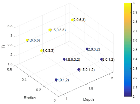
Figure 4: The influence of target parameters on Tr.
Firstly, we explored the minimum truncation order (Tr) for achieving convergence accuracy under different target parameters. In this study, we set the buried depth of the target to 1, 2, and 3, and the target radius to 0.1, 0.3, and 0.5, resulting in nine different combinations. By calculating the results under these combinations, we obtained Fig. 4. As shown in Fig. 4, with the increase of D and the decrease of R, interaction gradually decreases. This is mainly due to the decrease of target-rough surface interaction as the buried depth increases and the target radius decreases. Conversely, as D decreases and R increases, the target-rough surface interaction enhances, resulting in an increase of Tr. This phenomenon is consistent with our expectations because when the buried depth of the target increases, the signal propagation through the rough surface will be subject to greater attenuation and scattering. Therefore, a larger truncation order is required to accurately simulate this propagation process and achieve convergence accuracy.
In addition, we noticed that the minimum truncation order required to reach the convergence accuracy is different under different rough surface conditions. To further explore this phenomenon, we conducted experiments for different rough surface models and recorded the minimum truncation order required to reach convergence accuracy, as shown in Fig. 5. Among them, permittivity was taken as , , , and root mean square height was taken as , , . By comparing the experimental results, we found that changing the roughness of the rough surface did not change Tr; while increasing the permittivity, Tr gradually decreased. This is mainly because with the increase of permittivity, the reflection of the incident wave by the medium is enhanced, and the transmission is weakened, resulting in a decrease in the interaction between the rough ground and the target.
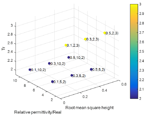
Figure 5: The influence of rough surface parameters on Tr.
In summary, in this investigation, we found that the selection of Tr is closely related to the final accuracy, and the target radius, burial depth, and permittivity have important effects on Tr. Therefore, in practical applications, it is necessary to choose an appropriate Tr based on target parameters and specific rough surface conditions to ensure that the convergence accuracy of the algorithm can meet the actual requirements. This finding has important significance for future research.
To further delve into the performance characteristics of the algorithm, a detailed study was conducted on memory and time consumption for calculating rough surfaces across different scales, with the relevant data summarized in Table 1. Upon thorough analysis, it was revealed that the algorithm exhibited outstanding computational performance, effectively demonstrating its efficiency and stability.
Table 1: Memory consumption and time of computations
| Memory (MB) | 206 | 309 | 432 |
| Time (sec) | 978 | 2226 | 2940 |
IV. NUMERICAL RESULTS AND ANALYSIS
Section IV reports the interaction between the target and the rough surface based on the G-PILE algorithm and analyzes the results, which are presented in Figs. 6 and 7.
According to Fig. 6, we can clearly see that the scattering coefficient of cylindrical targets exhibits a significant trend as the target radius changes. When the target radius increases, the scattering coefficient at all angles, except for the specular reflection direction, increases significantly. In the case of TE wave incidence, the scattering coefficient increases significantly in the range of -90 to 0. This indicates that as the target radius increases, the interaction between rough ground and the target gradually increases, resulting in a significant increase in the scattering coefficient. Especially in the case of TM wave incidence, the scattering coefficient at all angles except for the region of 0 to 30 shows a significant increase. This further indicates that the interaction between rough ground and the target increases with the increase of target radius, and this change is more significant in the case of TM wave incidence.
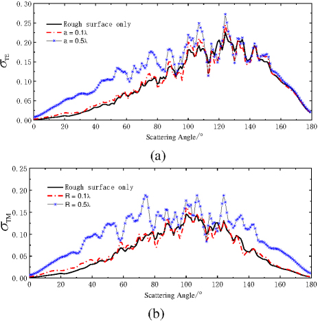
Figure 6: The influence of radius on scattering coefficient. (a) TE incident wave and (b) TM incident wave. Black curve Rough surface only; Red curve R=0.1; Blue curve R0.5.
In addition, Fig. 7 shows the trend of the scattering coefficient as a function of the target burial depth. When the target burial depth changes, the interaction between the target and the rough ground weakens, resulting in a decrease in the scattering coefficient. When TE waves are incident, the change in the scattering coefficient is relatively smooth. However, when TM waves are incident, the change in the scattering coefficient appears more significant. This indicates that the change in the target burial depth has a significant impact on the scattering coefficient, especially when TM waves are incident.
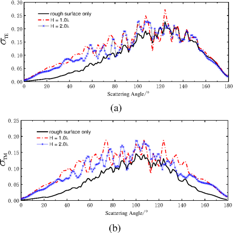
Figure 7: Influence of target depth on scattering coefficient. (a) TE incident wave and (b) TM incident wave.
From a comprehensive observation of Figs. 6 and 7, it can be concluded that due to the interaction between the target and the ground, when there is a target buried under the ground, its scattering coefficient is higher than that without a target. As this interaction increases(e.g., the increase in target radius or the decrease in burial depth), this difference becomes increasing more obvious, and vice versa. These observations indicate that the target radius and burial depth have a significant impact on the scattering coefficient. These results are of great significance for understanding and predicting the interaction between rough ground and targets, as well as the variation of scattering coefficients, and provide a reference for future research.
V. CONCLUSION
This article delves into an innovative algorithm called G-PILE, which is used to solve the complex electromagnetic scattering of large-scale dielectric rough surfaces and buried dielectric targets. Firstly, we establish the EFIE and comprehensively optimize and improve the traditional PILE algorithm. The improved algorithm not only overcomes the limitations of the traditional algorithm, which is only suitable for solving electromagnetic scattering problems of layered rough surfaces, but also extends its application range to studying the composite scattering characteristics of targets under roughsurfaces.
In the iterative solution process, this study introduces the BMIA/CAG method, which greatly reduces the complexity of the algorithm and significantly improves the solution efficiency. At the same time, we also introduce a conical incident wave, which further reduces the error introduced by rough surface truncation.
To verify the accuracy and validity of the G-PILE algorithm, we calculate the scattering characteristics of an infinitely long dielectric cylinder buried under a dielectric rough surface and compare the results with existing algorithms in detail. The comparison results show that the G-PILE algorithm exhibits superior performance and reliability in key aspects such as the surface field of rough surfaces, the composite electromagnetic scattering coefficient of rough surfaces and targets, and truncation convergence characteristics.
Finally, we investigate the composite electromagnetic scattering under different target parameters. These results have important theoretical and practical values for deepening our understanding and accurately predicting the interaction between rough ground and targets, as well as the changes in scattering coefficients. In addition, these results also provide valuable references for future research in related fields. By studying the influence of different target parameters on composite electromagnetic scattering, we can better understand the interaction mechanism between targets and rough surfaces and provide strong theoretical support for electromagnetic scattering prediction and control in practical engineering applications.
REFERENCES
[1] Q. K. Wang, C. M. Tong, X. M. Li, Y. J. Wang, Z. L. Wang, and T. Wang, “Composite electromagnetic scattering and high-resolution SAR imaging of multiple targets above rough surface,” Remote Sensing, vol. 14, no. 12, 2022.
[2] T. Liu, L. Zhang, Z. G. Zeng, and S. J. Wei, “Study on the composite electromagnetic scattering from 3D conductor multi-objects above the rough surface,”Radioengineering, vol. 30, no. 2, 2021.
[3] C. Y. Ma, Y. H. Wen, and J. B. Zhang, “A fast, hybrid, time-domain discontinuous Galerkin-physical optics method for composite electromagnetic scattering analysis,” Applied Sciences, vol. 11, no. 6, 2021.
[4] G. X. Zou, C. M. Tong, J. Zhu, H. L. Sun, and P. Peng, “Study on composite electromagnetic scattering characteristics of low-altitude target above valley composite rough surface using hybrid SBR-EEC method,” IEEE Access, vol. 8, 2020.
[5] H. L. Sun, C. M. Tong, and P. Peng, “Improved hybrid FEM/MOM combining MLFMA for composite electromagnetic scattering,” Electromagnetics, vol. 37, no. 8, 2017.
[6] J. Li, L. X. Guo, and S. R. Chai, “Composite electromagnetic scattering from an object situated above rough surface,” Applied Optics, vol. 53, no. 35, 2014.
[7] W. H. Ye, Z. S. Wu, H. Li, X. B. Wang, and J. J. Zhang, “A study of composite electromagnetic scattering from a simple target above an oceanic surface,” in ICMTCE 2011, Institute of Electrical and Electronics Engineers, Beijing, China, pp. 485-488, 2011.
[8] B. Sami, B. Christophe, and K. Gildas, “3-D scattering from a PEC target buried beneath a dielectric rough surface: An efficient PILE-ACA algorithm for solving a hybrid KA-EFIE formulation,” IEEE Transactions on Antennas and Propagation, vol. 63, no. 11, 2015.
[9] I. Mahariq, M. Kuzuoğlu, and I. H. Tarman, “On the attenuation of the perfectly matched layer in electromagnetic scattering problems with the spectral element method,” Applied Computational Electromagnetics Society (ACES) Journal, vol. 29, no. 9, pp. 701-710, 2021.
[10] I. Mahariq, H. Kurt, and M. Kuzuoğlu, “Questioning degree of accuracy offered by the spectral element method in computational electromagnetics,” Applied Computational Electromagnetics Society (ACES) Journal, vol. 30, no. 7, pp. 698-705,2021.
[11] A. Kizilay and M. S. Yucedag, “Investigation of TMz scattering from conducting target buried in two-layered lossy medium with flat surfaces using a decomposition solution,” Journal of Electromagnetic Waves and Applications, vol. 28, no. 5, 2014.
[12] S. Dey, W. G. Szymczak, A. Sarkissian, and J. A. Bucaro, “Scattering from targets in three-dimensional littoral and surf-zone environments with multi-layered elastic sediments based on an interior-transmission formulation,” Computer Methods in Applied Mechanics and Engineering, vol. 260, 2013.
[13] Y. S. Choo, G. Y. Choi, K. H. Lee, S. H. Byun, and Y. M. Choo, “Ray-based analysis of subcritical scattering from buried target,” Journal of Marine Science and Engineering, vol. 11, no. 2, 2023.
[14] X. K. Li, Y. S. Wu, G. Yu, and Y. F. Zou, “Acoustic scattering of buried stainless steel spheres: Theoretical analysis and experimental verification,” Applied Acoustics, vol. 173, 2021.
[15] X. K. Li and Y. S. Wu, “Feature extraction for acoustic scattering from a buried target,” Journal of Marine Science and Application, vol. 18, no. 3, 2019.
[16] V. M. Klibanov, E. A. Kolesov, and L. D. Nguyen, “Convexification method for an inverse scattering problem and its performance for experimental backscatter data for buried targets,” SIAM Journal on Imaging Sciences, vol. 12, no. 1, 2019.
[17] G. S. Kargl, L. A. Espana, and L. K. Williams, “Scattering from a partially buried target: A modified acoustic ray model,” The Journal of the Acoustical Society of America, vol. 138, no. 3, 2015.
[18] H. J. Simpson, Z. J. Waters, B. H. Houston, K. K. Jig, R. R. Volk, T. J. Yoder, and J. A. Bucaro, “Acoustic imaging and structural acoustic analysis of laboratory measurements of scattering from buried targets above critical grazing angles,” The Journal of the Acoustical Society of America, vol. 130, no. 4, 2011.
[19] J. Z. Waters, “Acoustic imaging and structural acoustic analysis of scattering from buried targets at above-critical grazing angles,” The Journal of the Acoustical Society of America, vol. 130, no. 4, 2011.
[20] A. Ishimaru, J. D. Rockway, and Y. Kuga, “Rough surface Green’s function based on the first-order modified perturbation and smoothed diagram methods,” Waves Random Media, vol. 10, no. 1, 2000.
[21] A. Iodice, G. Di Martino, A. D. Simone, D. Riccio, and G. Ruello, “Electromagnetic scattering from fractional Brownian motion surfaces via the small slope approximation,” Fractal and Fractional, vol. 7, no. 5, 2023.
[22] X. H. Li, “Research on the electromagnetic scattering from foam sea based on small slope approximation,” The Journal of Engineering, no. 4, 2021.
[23] I. Mahariq, “On the application of the spectral element method in electromagnetic problems involving domain decomposition,” Turkish Journal of Electrical Engineering and Computer Sciences, vol. 25, no. 2, 2017.
[24] M. Sanamzadeh, L. Tsang, J. Johnson, R. Burkholder, and S. Tan, “Electromagnetic scattering from one dimensional random rough surfaces of dielectric layered media with waveguide modes using second order small perturbation method,” Progress in Electromagnetics Research B., vol. 80, 2018.
[25] T. Fang and Z. Cao, “Electromagnetic scattering modeling from Gaussian rough surface based on SPM,” in ICCT 2017, Institute of Electrical and Electronics Engineers, Chengdu, China, pp. 1791-1795, 2017.
[26] J. S. Tian, J. Tong, J. Shi, and L. Q. Gui, “A new approximate fast method of computing the scattering from multilayer rough surfaces based on the Kirchhoff approximation,” Radio Science, vol. 52, no. 2, 2017.
[27] M. Man, Z. Lei, Y. Xie, and X. Li, “Bistatic RCS prediction of composite scattering from electrically very large ship-sea geometry with a hybrid facet-based KA and shadow-corrected GRECO scheme,” Progress in Electromagnetics Research B, vol. 60, no. 1, 2014.
[28] X. C. Ren, L. X. Guo, and D. Y. Ma, “Electromagnetic scattering from 2D band-limited Weierstrass fractal dielectric rough surface using Kirchhoff approximation,” in Chinese Institute of Electronics 2006, 7th International Symposium on Antennas, Propagation and EM Theory Proceedings Volume II of II. Institute of Electrical and Electronics Engineers, pp. 274-277, 2006.
[29] X. Wang, C. F. Wang, and Y. B. Gan, “Electromagnetic scattering from a circular target above or below rough surface,” Progress In Electromagnetics Research, vol. 40, 2003.
[30] L. Tsang, J. A. Kong, and K. H. Ding, Scattering of Electromagnetic Wave: Numerical Simulation. New York: John Wiley & Sons, 2001.
[31] A. Thorsos, “The validity of the Kirchhoff approximation for rough surface scattering using a Gaussian roughness spectrum,” Journal of the Acoustical Society of America, vol. 83, no. 1, 1988.
BIOGRAPHIES

Juan Zhao was born in Jiangxi, China. She received the bachelor’s and master’s degrees from Jiangxi Normal University, Jiangxi, China, in 2003 and 2009, respectively. Her research interests include computer applications and computer communication.
ACES JOURNAL, Vol. 40, No. 5, 409–418
doi: 10.13052/2025.ACES.J.400504
© 2025 River Publishers