Equivalent Circuit Model for Convoluted Meander Line Frequency Selective Surface for Multi-frequency Applications
Deepa Jeyaraman and Suganthi Santhanam
Department of Electronics and Communication Engineering
K. Ramakrishnan College of Technology, Trichy, Tamil Nadu, India
shanjeya0308@gmail.com, suganthis.ece@krct.ac.in
Submitted On: November 25, 2023; Accepted On: September 5, 2024
ABSTRACT
This research investigates a multi-resonant frequency selective surface (FSS) structure with convoluted meander line. An equivalent circuit analysis was conducted in three different 1010 array structures having 200 mm 200 mm size with 10 mm 10 mm unit cell. The simple plus structure achieved a single resonant frequency of 10 GHz at 27 dB, dual frequencies of 4.6 GHz at 22 dB and 11.6 GHz at 28 dB while increasing the length of meander lines to three turns. By adding an extra six turns for a total of nine turns, the structure achieved three resonant frequencies of 3.4G Hz at 28 dB, 10.6 GHz at 22 dB and 16 GHz at 20 dB. The polarization insensitivity and transmission coefficient in transverse electric (TE) and transverse magnetic (TM) modes has been validated with the equivalent circuit model (ECM) and tested with measurement also. The result demonstrates that the proposed FSS can be applied for WiMax, X and Ka-band wireless communication and radar systems applications.
Index Terms: Convoluted meander line, frequency selective surface, polarization insensitivity, transmission coefficient, wireless communications.
I. INTRODUCTION
Frequency selective surfaces (FSS) have emerged as a key technology in various fields of electromagnetic wave engineering due to their ability to selectively control the transmission and reflection of electromagnetic waves at specific frequencies [1–3]. However, they might not fully address real-world problems such as difficulty in fabrication, scaling concerns and performance constraints in particular scenarios. Meander line structures have been widely used in FSS design to achieve multi-resonant behavior [4–6], further improved by using convoluted meander lines. These works might not include in-depth analyses of constrained bandwidth, sensitivity to environmental changes and challenges in attaining desired resonant behavior over a broad frequency range. Convoluted meander line structures differ from traditional meander lines by incorporating folds or curves. Polarization insensitivity as a result of the uneven composition has been reported in [7] and shows angular stability under transverse electric (TE) and transverse magnetic (TM) modes from 0 to 80 with a minimum frequency deviation of less than 1% but at lower frequency band from 1 to 2 GHz only. FSS structures having conductive path extension and higher inductance value has been proposed for 5.5 GHz WLAN applications [8]. References [9–11] demonstrate the approach to enhance the resonant behavior of FSS to operate at multiple frequencies.
Many researchers have proposed the different types of convoluted meander line structures, such as zigzag [12–14], serpent [15–17] and square convoluted meander lines [18, 19]. These studies examined the resonant characteristics of FSS structures based on convoluted meander lines, and designed and analyzed three different convoluted meander line structures, each with increasing numbers of turns, to explore their resonant behavior. The equivalent circuit model (ECM) was used to obtain inductance and capacitance values for each structure, providing insights into the underlying physics [20–22]. These results demonstrated the potential of convoluted meander lines for achieving multi-resonant frequency behavior in FSS, with potential applications in numerous fields [23–25]. Recent advancements in FSS technology have led to the development of new structures with improved performance. For instance, the use of fractal geometries has been shown to enhance the bandwidth and polarization selectivity of FSS structures [26–28]. Similarly, the incorporation of metamaterials has enabled the design of FSS structures with unique characteristics like inverse refraction index and complete absorption [29–31]. However, the use of convoluted meander lines remains an attractive option due to its simplicity and versatility. The structures can be easily fabricated using standard photolithography techniques, and their performance can be easily optimized by adjusting the quantity of rotations and the distance between meander lines [32–34]. Moreover, the resonant behavior of convoluted meander line FSS structures can be further enhanced by incorporating additional elements such as slots and patches [35–37].
These elements can introduce flexibility in the design process, resonant frequencies and bandwidths variation. In summary, convoluted meander line structures have emerged as a promising approach for achieving multi-resonant behavior in FSS structures. Miniaturization is one of the reasons to overcome these constraints, especially with regard to unit cell size [7]. Smaller unit cells in FSS and meander line architectures are frequently preferred for a variety of uses, including integrated microwave components or compact antenna designs. It is difficult to achieve miniaturization without sacrificing performance. At smaller scales, fabrication techniques might find it difficult to produce exact features, which would raise complexity and cost. Reducing the size of unit cells can also bring additional electromagnetic phenomena that influence the behavior of the device, for impacts of surface roughness or heightened sensitivity [8] to surrounding objects or substrate qualities. Proposing new fabrication methods that are optimized for miniaturization and creative design strategies that lessen the effects of environmental influences are crucial. Overcoming these obstacles advances our knowledge of FSS and meander line topologies while also paving the way for more reliable and useful applications across a range of industries.
A compact single-layer bandstop FSS with good angular and resonant stability is presented in [38]. In contrast, [39] introduces a single-layer band pass FSS that resonantly covers the entire X-band (8-12 GHz) with good polarization and angular stability, thanks to tunable filter elements. The smaller size of the unit cell [39] may prevent it from providing a solution as compact, and it does not emphasize the miniaturization. Reference [40] suggested downsized double stop-band FSS for WLAN was built on the cross-zigzag loaded line and internal branches of a ring patch.
Hexagonal split-ring 2.5-dimensional unit cell is suggested in [41] for applications involving FSS. A metallic structure that has a dual-bandstop feature and a convoluted meander line incorporated cross dipole is presented in [42]. The fabrication of microwave components has made use of various additive manufacturing (AM) techniques and those are discussed in [43]. A compact single-layer bandstop FSS with good angular and resonant stability is presented in [44]. A novel tri-band complementary frequency selective surface (CFSS) with a conventional geometry made up of double concentric rings was proposed by the authors in [45]. FSS with gain improvement is included in an efficient ultra-wideband (UWB) cyclic monopole antenna, as reported in [46]. In [47] the grating lobes are used for miniaturization and create a reduced single-layer FSS operating at 2.6 GHz. Using square loop, ring loop and cross dipole structures on a single layer, two small dual-band FSS structures [48] and a tri-band FSS [49] and low-profile tri-band bandpass FSS using two-dimensional repetition of a unit cell with four apertures [50] are detailed for the investigation of angle variation.
In this research article, we presented a novel miniaturized tri-band FSS featuring meander lines. We proposed the design and analysis of three different FSS structures, each exhibiting a resonant frequency that varies as the convoluted meander line’s length and turns are adjusted. To illustrate our approach, we introduce the suggested FSS arrangement along with unit cell schematic and an equivalent circuit. Miniaturization has been achieved with a unit cell having dimensions 10 mm 10 mm. The characteristics of structure have been evaluated with different polarizations and angles of incidence of the planar wave. After many trials, three structures have been chosen and the optimized FSS 3 structure is proposed to a wide range of WiMax, X-band and Ka-band wireless communications and radar system applications that use FSS to reflect, absorb or transmit electromagnetic waves, which improve radar effectiveness in applications such as surveillance, navigation and target detection. The FSS’s polarization insensitivity and high transmission coefficient highlight its potential for a wide range of communication and radar applications, displaying versatility and performance across multiple frequency bands. This analysis aims to evaluate the effectiveness and performance of the proposed FSS 3.
The uniqueness of our proposed work has been listed here.
Multi-resonant FSS with convoluted meander lines
Design evolution for miniaturization
Equivalent circuit model analysis
Tri-band resonant behavior: At 3.4 GHz, 10.6 GHz and 16 GHz. This tri-band behavior is a significant advancement, offering versatility for applications requiring operation across multiple frequency bands.
Stability and polarization insensitivity
Compact and cost-effective design.
II. DESIGN EVOLUTION
The meander line length from FSS 1 to FSS 3 has been decided based on the change in resonant frequency which in turn depends on the inductance and capacitance values. The turns in the meander lines have been increased to alter the electrical characteristics at multiple frequencies simultaneously, as demonstrated by the tri-band behavior in FSS 3. The other parameters like meander line length and slot are obtained by equations (1) and (2).
The design process from FSS 1 to FSS 3 with change in turns number has been depicted in Figs. 1 (a-c). The design has been fabricated on a FR4 substrate having thickness of 1 mm, permittivity of 4.3 and loss tangent of 0.02 to be cost-effective compared to Roger material which was used by most of the researchers in the literature. The permittivity of 4.3 gives precise electrical resistance to successfully manipulate electromagnetic waves inside the structure, and low loss tangent of 0.02 guarantees the signals pass with minimal loss. A magnetic susceptibility of 1 signifies the substrate’s non-responsiveness to magnetic fields, which simplifies the process of designing and analyzing the FSS structure.
For conducting simulations, the CST Microwave Studio simulation tool is used for employing periodic boundary conditions based on Flouquet’s method. First, FSS 1 is designed in a plus-shaped structure as shown in Fig. 1 (a) that results in single resonant frequency. To improve the performance of the structure to multi-band, FSS 1 has been extended with an L-shaped slot connected at each end of the plus structure and thereby increasing the meander line with three turns as depicted in Fig. 1 (b). To examine the connection between meander line length and resonant frequency, we incorporated two more L-shapes as meander lines with six turns, as presented in Fig. 1 (c).
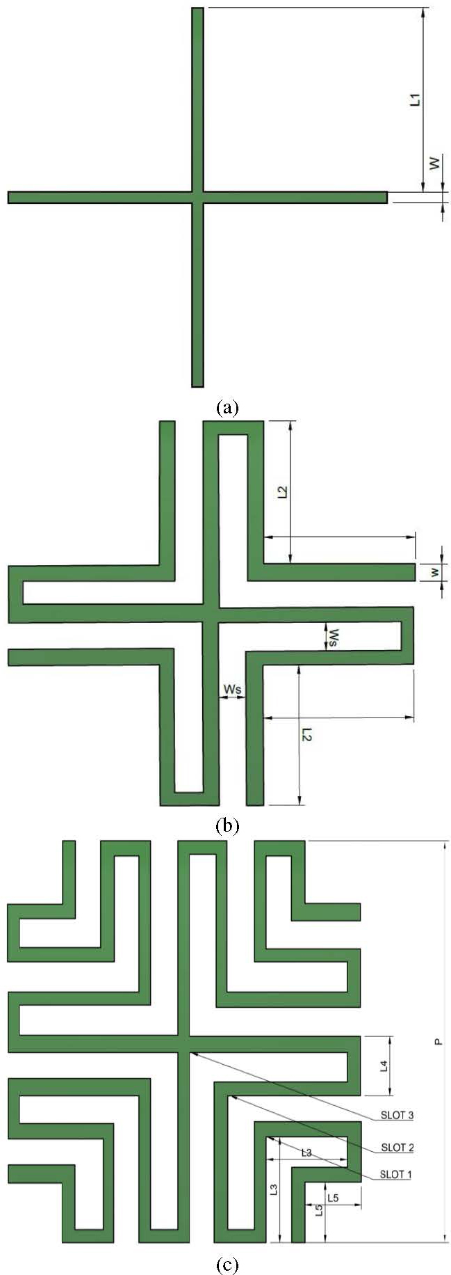
Figure 1: FSS structure design: (a) FSS 1, (b) FSS 2, and (c) FSS 3.
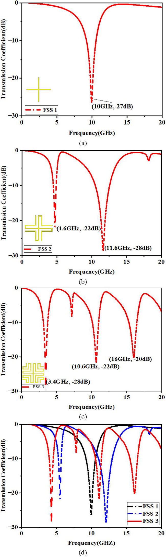
Figure 2: Transmission properties: (a) FSS 1, (b) FSS 2, (c) FSS 3, and (d) comparison of all structures.
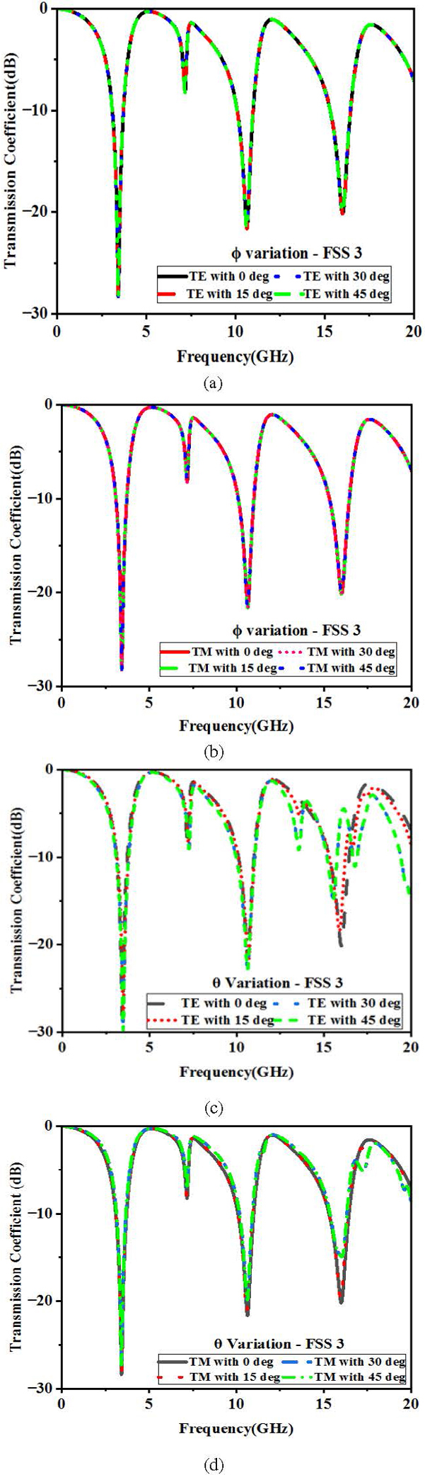
Figure 3: Transmission co-efficient of single-layer FSS 3 with various and : (a) and (c) TE mode and (b) and (d) TM mode.
The transmission characteristic of FSS 1 resonates at 10 GHz and dual resonant frequency was observed from the FSS 2 structure at 4.7 GHz and 11.6 GHz as shown in Figs. 2 (a) and (b). With a meander line length increase, due to inductive reactance variation, the FSS 3 structure exhibits tri-band resonant transmission characteristics at 3.4 GHz, 10.6 GHz and 16 GH as shown in Fig. 2 (c). The shift in resonant frequency for the additional slot introduced has been compared in Fig. 2 (d). The optimum dimensions of unit cell were chosen after many trials and based on defined formulas. They are p10 mm, l4.6 mm, W0.3 mm and W0.7 mm, with a unit cell free space wavelength of 0.038. The dimensions of a single-layer FSS having convoluted meander line FSS design has been calculated using equations (1) and (2). Each unit cell is composed of 10 metallic strips featuring nine turns with length decided by:
| (1) |
The slots dimension is given by:
| (2) |
The stability of the proposed FSS 3 is investigated in terms of its polarization as shown in Fig. 3. For the FSS 3 structure, the signal transmission efficiency has been analyzed for 0 to 45 and values at both TE mode and TM mode. It proves good stability with 0% shift in frequency at triple band having 3.4 GHz, 10.6 GHz and 16 GHz resonant frequencies at both TE mode and TM mode for different polarizations. The resonance is maintained across all four values of , with the transmission coefficients being 28 dB, 21.5 dB and 20 dB for the three bands, respectively. In Figs. 3 (c) and (d), the proposed FSS 3 is examined for vertical and horizontal polarizations, respectively.
When the angle of incidence is 0 for vertical polarization, FSS 3 displays a tri-band with 0% shift. At =15, there is a 0.2% shift in the resonant frequency at 16 GHz, which changes to 15.8 GHz at 19 dB. Similarly, at =30, the resonant frequency shows a 0.2% shift, resulting in a value of 15.6 GHz at 15 dB. However, at =45 there is no shift, and the resonant frequency remains the same as that at 30.
For horizontal polarization at =0, there is a 0% shift in all three resonant frequencies. At =15, there is no change in the first and second resonant frequencies, but there is a 0.2% shift in the return loss at 16 GHz from 20 dB to 19.8 dB. At =30 and =45, there is a 0% shift in the 3.4 GHz resonant frequency, while there is a 0.1% shift in the return loss of the 10.6 GHz resonant frequency from 21.7 dB to 20.1 dB. The return loss for 16 GHz resonant frequency shifts from 20 dB to 15 dB, but the resonant frequency remains stable at 16 GHz.
III. EQUIVALENT CIRCUIT MODEL
Monitoring the electric and magnetic field distributions is an important task throughout the development process of FSS structures. Particularly, the electric field distribution holds significant value as it reflects the conservation of energy within the unit cell. Analyzing this electric field distribution enables the identification of the resonant frequencies of the FSS configuration. To design these resonances effectively, an equivalent LC resonant circuit can be employed, which can be applied in addition to transmission line section, especially when dealing with convoluted meander line structures. This method is highly effective in determining resonant frequencies of FSS structures, which is vital for optimizing their performance. Furthermore, studying the distribution of electric and magnetic fields can lead to a better comprehension of the behavior of FSS structures, which in turn can enhance their design and performance.
Figure 4 (a) shows the simulated electric field distribution of 22 unit cell array. From the figure it is understood that the field distribution is of higher strength at the vertical end of the plus slot rather than at the center. The electric field distribution of FSS 1 displays a strong concentration of charges at both the top and bottom edges, resulting in a dominant capacitive effect.
Figure 4 (b) displays the ECM of an individual layer FSS unit cell as the series LC resonator having free space wave impedance, Z 377 . The inductance L represents the metallic strip and the coupling between strips represents the capacitance C. Figure 4 (c) shows the comparison of transmission coefficient at 10 GHz for full wave analysis and equivalent circuit model analysis having lumped parameters L 0.679 nH and C 0.37 pF. The ability of signal propagation is slightly higher in simulation than the ECM model but no shift in resonant frequencies was observed.
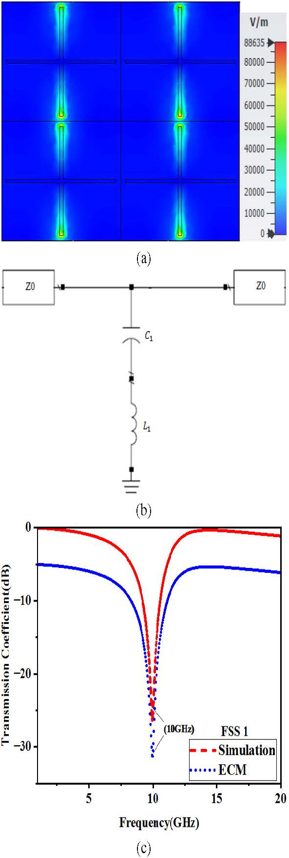
Figure 4: (a) Electric field distribution at 10 GHz, (b) ECM circuit, and (c) Comparison between full wave and the ECM analysis of FSS 1.
This analogous circuit model-series LC resonator is used to represent the basic behavior of the FSS. The resonant behavior of the FSS at particular frequencies and the relationship that exists between the external electromagnetic fields and the FSS structure has been derived from this circuit. The relationship between the circuit parameters and the proposed FSS parameters is outlined based on [51]:
| (3) |
| (4) |
The impedance Z of the ECM can be obtained by calculating the sum of the dimensions of the meander lines (L) and the dimensions of the meander slots (L).
| (5) |
where Z is ECM’s impedance equivalent. Utilizing the tenets of wave propagation, the transmission factor of the novel ECM can be determined through the subsequent calculation:
| (6) |
By examining the equivalent circuit, we can deduce that when Z = 0 , three transmission zeros are present, and when Z = , one transmission pole exists. Equation (7) can be utilized to calculate the frequencies of these zeros and poles:
| (7a) | ||
| (7b) | ||
| (7c) |
The electric field distribution of two parallel LC sections as a result of convoluted meander lines addition has been analyzed in Fig. 5. The electric field distribution of the resultant FSS 2 structure exhibits a greater concentration of charges at the edges of the convoluted meander lines in comparison to FSS 1, as displayed in Fig. 5 (a).
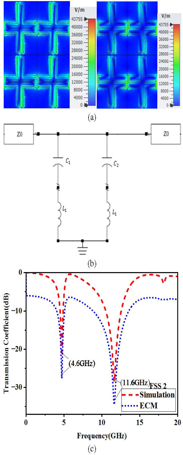
Figure 5: (a) Electric field distribution at 4.6 GHz and 11.6 GHz, (b) ECM circuit, and (c) Comparison between full wave and the ECM analysis of FSS 2.
Unlike in FSS 1, all four ends of the plus slot have been charged equally with electric fields due to additional L slots in the form of convoluted meander lines. The ECM and comparison of transmission behavior between the ECM and full wave simulation are displayed in Figs. 5 (b) and (c), respectively. The calculated and simulated optimum LC values are: L=4 nH and C=0.29 pF, L=0.2 nH and C=0.94 pF. The transmission behavior is similar to FSS 1 at 4.6 GHz and 11.6 GHz dual resonant frequency.
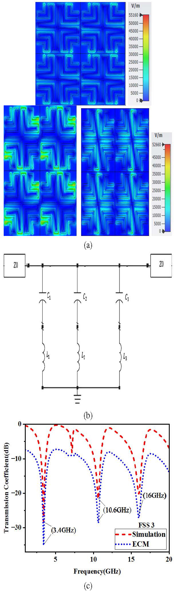
Figure 6: (a) Electric field distribution at 3.4 GHz, 10.6 GHz and 16 GHz, (b) ECM model, and (c) Comparison of full wave and ECM model transmission of FSS 3.
FSS 3 has been analyzed at 3.4 GHz, 10.6 GHz and 16 GHz resonant frequencies as shown in Fig. 6. The derived LC values for the meander lines having higher number of turns are: L=4 nH and C=0.55 pF, L=0.55 nH and C=0.41 pF, and L=0.5 nH and C=0.196 pF. The combination of three different inductances and capacitances were connected in parallel, as illustrated in Fig. 6 (b), was simulated and compared with the full-wave simulation of FSS 3 behavior presented in Fig. 6 (c).The comparison shows strong agreement between simulation and ECM analysis with no shift in frequency at three resonant frequencies.
It is important to note that these parameters are specific to the circuits proposed in the respective figures mentioned above. Figures 4, 5 and 6 indicate that a single resonant frequency of 10 GHz can be demonstrated by a single plus structure (FSS 1) and with increase in meander line length by three turns, a dual resonant frequency is achieved at 4.6 GHz and 11.6 GHz. Subsequently, the FSS 3 structure, which includes an additional six turns in the meander lines, achieves tri-band resonant frequencies at 3.4 GHz, 10.6 GHz and 16 GHz.
IV. MEASUREMENT ANALYSIS OF RESULTS
Measurements entail the usage of two wide-range horn antennas along with a vector network analyzer with the proposed FSS prototype at the center point between two horn surfaces as shown in Fig. 7 (a). The single-layer FSS created to demonstrate the simulated performance has been fabricated with 200 mm 200 mm size as shown in Fig. 7 (b), accompanying an assembly of 2020 individual unit cell. The unit cell of fabricated single-layer FSS for 10 mm 10 mm is shown in Fig. 7 (c).
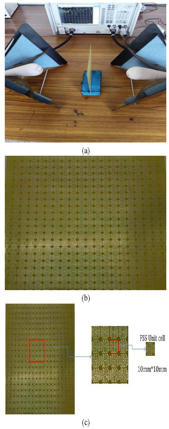
Figure 7: FSS 3 structure: (a) measurement set up, (b) fabricated prototype, and (c) unit cell.
The measured TE and TM mode transmission coefficient for value from 0 to 45 degree in a 15-degree increased step size has been plotted in Figs. 8 (a) and (b), respectively. A multi-frequency reaction is observed with an augmentation in meander lines, and the points of zero transmission remain unwavering across different angles of incidence for both TE and TM mode polarizations, aligning through exhaustive wave simulations. Polarization insensitivity has been achieved for angle variation at multi frequency and proved through measurement. The discrepancy of 5 dB between the calculated and simulation results for the proposed three types of FSS is due to:
i) The ECM as a set of lumped circuit elements may not fully capture the intricacies of the actual electromagnetic interactions.
ii) Assumptions made in developing the ECM, such as neglecting mutual coupling between adjacent unit cells or ignoring edge effects, can lead to inaccuracies in the calculated results.
iii) Variations in fabrication tolerances, material properties or environmental conditions.
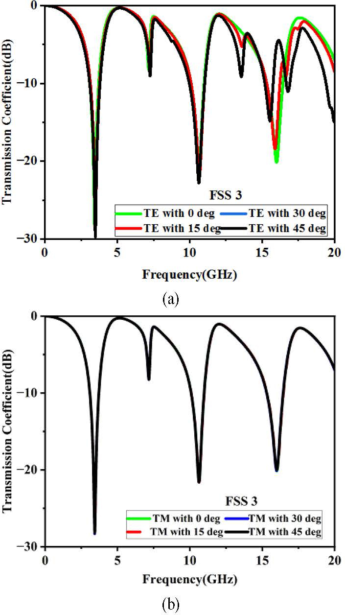
Figure 8: Measurement of transmission coefficient of FSS 3 using network analyzer: (a) TE mode and (b) TM mode.
For easy understanding, the simulated and measured TE mode results of frequency shift for polarization insensitivity have been compared for an angle range from 15 to 45 as shown in Table 1. We observed zero frequency in simulation for all three resonant frequencies and this shift changes up to 0.2% in measurements. Similarly, the transmission coefficient has gained shift at third resonant frequency for all angle values and no change for the remaining two resonant frequencies.
Table 1: Comparison of simulated and measured results for TE mode
| Degree | Simulated | Measured |
| Transmission Coefficient (dB) | ||
| 15 | 28 @ 3.4 GHz | 20 @ 15.9 GHz |
| 30 | 21 @ 10.6 GHz | 15 @ 15.8 GHz |
| 45 | 20 @ 16 GHz | 15 @ 15.8 GHz |
| Shift in Frequency (GHz) | ||
| 15 | No shift | 0.1% @ 15.9 |
| 30 | 0.2% @ 15.8 | |
| 45 | 0.2% @ 15.8 |
Table 2: Parametric comparison with other works
| Ref | Thickness (mm) |
Layer | Band | shift (%) & () |
|
| [38] | 1 | 4.4 | 2 | 2 | 0.9 & 60 |
| [39] | 1 | 4.4 | 2 | 1 | 0.8 & 60 |
| [40] | 0.4 | 4.4 | 1 | 2 | 2.2 & 85 |
| [41] | 0.125 | 2.7 | 1 | 1 | 6.93 & 45 |
| [42] | 1 | 4.3 | 1 | 1 | 6 & 60 |
| This Work | 1 | 4.4 | 1 | 3 | 0.2 & 45 |
The other notable achievement of this proposal, miniaturization, has been evidently compared with other similar FSSs having a single-layer for three band application as in Table 2. It is noticed that the frequency change with respect to angle is negligible at 0.2%, and happens at 45 degrees with size reduction of about half in both length and width of FSS as compared to [50] and [45] given in Table 3.
Table 3: Unit cell size and bands comparison with other works
| References | Number of Bands | Number of Layers | Size (mm) |
|---|---|---|---|
| [50] | 3 | Single | 20.6 20.6 |
| [47] | 1 | Single | 9.45 9.45 |
| [48] | 2 | Single | 11.2 11.2 |
| [46] | 1 | Single | 30 30 |
| [49] | 3 | Single | 24 22 |
| [45] | 3 | Single | 24 24 |
| This Work | 3 | Single | 10 10 |
The proposals in [50], [49] and [45] achieved three bands with a single layer, but with higher size which is more than twice compared to our design. In contrast, [47] shows smaller unit cell diameters than the others but with a single band. These dimensions differ greatly amongst references, reflecting different designs and applications. This shows the newness of our work having tri-band application aimed at compactness.
V. CONCLUSION
In this study, a miniaturized approach of FSS structure having single layer and periodicity of 10 mm for triple band wireless application has been presented. To achieve the desired performance, the convoluted structure based on meander lines was fabricated in FR4 substrate having well-defined dielectric properties and magnetic permeability. The proposed FSS in three versions has been simulated for single, dual and triple band resonant frequency. FSS 3 for triple band has been fabricated at 200 200 mm as an assembly of 2020 individual unit cells. The structure exhibited tri-band resonance at 3.4 GHz, 10.6 GHz and 16 GHz, with a shift of 0% in frequency for both TE and TM mode, proving its stability for different polarizations. The resonance was maintained across all values of , with transmission coefficients being 28 dB, 21.5 dB and 20 dB for the three bands, respectively. FSS 3 was also examined for vertical and horizontal polarizations, and it was found that it had good stability for different angles of incidence . This paper demonstrates that the proposed FSS structure can be utilized for various applications in the field of wireless communications.
ACKNOWLEDGMENT
The authors acknowledge the management for K. Ramakrishnan College of Technology for providing this research opportunity.
REFERENCES
[1] Y. Zhang, W. Liu, R. Liu, and F. Yang, “Frequency selective surface with independently controllable transmission and reflection characteristics,” Appl. Phys. Lett., vol. 115, no. 14, p. 141902, 2019.
[2] M. A. Al-Joumayly and A. Y. Al-Qudsi, “Frequency-selective surfaces for antenna applications: A review,” IET Microw. Antennas Propag., vol. 13, no. 6, pp. 742-750, 2019.
[3] E. Karaboga and Z. Bayraktar, “Dual-band frequency selective surface with multilayered and hexagonal unit cell,” IEEE Trans. Antennas Propag., vol. 69, no. 2, pp. 836-842, 2021.
[4] Y. Wang, X. Huang, Y. Yu, and J. Chen, “Design and analysis of a broadband frequency selective surface with simple meander line unit cells,” IET Microw. Antennas Propag., vol. 14, no. 11, pp. 1119-1125, 2020.
[5] L. Guo, Y. Tang, X. Zhang, and X. Han, “Multi-band frequency selective surface with fractal meander line for electromagnetic interference shielding,” Appl. Phys. A, vol. 126, no. 8, pp. 1-9, 2020.
[6] Y. Sun and Z. Zhu, “Dual-band polarization-independent frequency selective surface based on modified square-loop meander line,” IET Microw. Antennas Propag., vol. 14, no. 5, pp. 458-465, 2020.
[7] J. Garg, M. M. Sharma, and S. Yadav, “Design of a compact band pass frequency selective surface for WLAN applications based on meander line topology,” in 2021 IEEE Indian Conference on Antennas and Propagation (InCAP), pp. 893-896,2021.
[8] K. S. Yeo, H. C. Park, D. Ahn, and N. H. Myung, “A miniature band-pass filter using a meandered line,” IEEE Microw. Wireless Compon. Lett., vol. 12, no. 11, pp. 443-445, Nov. 2002.
[9] R. F. Harrington and J. R. Mautz, “Theory and experiment for periodic resonant structures,” IEEE Trans. Microw. Theory Tech., vol. 16, no. 4, pp. 182-186, Apr. 1968.
[10] K. Kim, K. Lee, K. Lee, and B. Lee, “Miniaturized filters using fractal-shaped resonators with complementary split ring resonators and meander lines,” IEEE Trans. Microw. Theory Tech., vol. 56, no. 11, pp. 2578-2586, Nov. 2008.
[11] J. E. Schutt-Aine and M. J. Howes, “An accurate equivalent circuit for meander lines and its application to coupled-line filters,” IEEE Trans. Microw. Theory Tech., vol. 44, no. 11, pp. 1957-1963, Nov. 1996.
[12] C. W. See and R. A. York, “Meander line bandpass filter design for harmonic suppression,” IEEE Trans. Microw. Theory Tech., vol. 49, no. 12, pp. 2355-2360, Dec. 2001.
[13] C. F. Tsai and L. J. Chen, “Design and performance of meander line filters with short-circuited stubs,” IEEE Trans. Microw. Theory Tech., vol. 50, no. 4, pp. 1219-1225, Apr. 2002.
[14] A. H. Aghvami and R. N. Simons, “Meander-line filters for VHF/UHF applications,” IEEE Trans. Microw. Theory Tech., vol. 29, no. 7, pp. 733-736, July 1981.
[15] K. W. Chau and K. M. Luk, “High-performance compact filters using folded meander-line resonators,” IEEE Microw. Wireless Compon. Lett., vol. 13, no. 8, pp. 329-331, Aug. 2003.
[16] J. W. Lee and K. Chang, “Miniaturized low-pass filter using L-shaped meander line,” IEEE Microw. Wireless Compon. Lett., vol. 12, no. 6, pp. 230-232, June 2002.
[17] M. Agostini, F. Freschi, and G. Ghione, “Modeling of lossy meander lines in multilayered substrates by a frequency-dependent surface impedance approach,” IEEE Trans. Microw. Theory Tech., vol. 44, no. 4, pp. 573-579, Apr. 1996.
[18] H. J. Tang, Q. Xue, and B. Wei, “A novel UWB bandpass filter based on a coupled meander line and SIRs,” IEEE Microw. Wireless Compon. Lett., vol. 22, no. 2, pp. 58-60, Feb. 2012.
[19] J. Zhang and Q. Xue, “Novel microstrip bandpass filter with meander lines and resonant stubs,” IEEE Microw. Wireless Compon. Lett., vol. 30, no. 5, pp. 413-415, May 2020.
[20] S. Chen, C. Yu, Y. Chen, S. Zhang, and Y. Liu, “Compact wideband bandpass filter based on E-shaped resonator with dual band-notched function,” Microwave Opt. Technol. Lett., vol. 61, no. 1, Jan. 2019.
[21] Z. Chen, X. Chen, C. Liu, H. Wang, and Y. Fan, “Miniaturized wideband bandpass filter with a novel perturbation technique,” J. Electromagn. Waves Appl., vol. 33, no. 3, pp. 241-250,2019.
[22] K. Fang, Y. Zhang, X. Yang, and M. Hu, “Design of compact dual-band bandpass filter with high isolation and low loss,” Micromachines, vol. 11, no. 1, Jan. 2020.
[23] M. Han, X. Mao, and G. Zhang, “Design of a compact quad-band bandpass filter with multiple transmission zeros,” Microwave Opt. Technol. Lett., vol. 62, no. 5, May 2020.
[24] L. Deng, H. Chen, S. Wang, Y. Huang, and Y. Wang, “Novel miniaturized bandpass filters based on substrate integrated waveguide,” J. Electromagn. Waves Appl., vol. 34, no. 13, pp. 1682-1694, 2020.
[25] C. Zhang, X. Chen, Q. Wu, and Y. Yuan, “Fractal frequency selective surfaces with multi-band characteristics,” Microwave Opt. Technol. Lett., vol. 61, no. 6, pp. 1639-1642, 2019.
[26] Y. Zhang, W. Xu, and L. Wang, “Fractal-inspired multiband frequency selective surface with polarization selectivity,” IEEE Trans. Antennas Propag., vol. 67, no. 7, pp. 4506-4510, 2019.
[27] Y. Zhang, W. Xu, and L. Wang, “A novel multiband fractal frequency selective surface with polarization selectivity,” Prog. Electromagn. Res. C, vol. 91, pp. 79-88, 2019.
[28] C. R. Simovski, P. A. Belov, A. V. Atrashchenko, and Y. S. Kivshar, “Metamaterial-based perfect absorbers: Ultrathin structures and localization of the absorbed energy,” Phys. Rev. B, vol. 85, no. 19, p. 195111, 2012.
[29] N. Liu, H. Liu, S. Zhu, and H. Giessen, “Three-dimensional photonic metamaterials at optical frequencies,” Nat. Mater., vol. 7, no. 1, pp. 31-37, 2008.
[30] X. Chen, T. M. Grzegorczyk, B.-I. Wu, J. Pacheco, and J. A. Kong, “Robust method to retrieve the constitutive effective parameters of metamaterials,” Phys. Rev. E, vol. 70, no. 1, p. 016608, 2004.
[31] F. Yang, J. Li, and Q. Li, “Wide-angle polarization-independent infrared frequency selective surface with a three-layer structure,” J. Appl. Phys., vol. 107, no. 1, p. 014510, 2010.
[32] K. Zhang, Y. Jiang, and X. Chen, “Design of frequency selective surfaces with controllable multiple passbands,” J. Appl. Phys., vol. 124, no. 15, p. 154303, 2018.
[33] J. Li, L. Li, and W. Li, “A miniaturized dual-bandstop frequency selective surface with meander line,” IEEE Antennas Wireless Propag. Lett., vol. 16, pp. 266-269, 2017.
[34] R. Garg and P. Bhartia, “Design of bandstop frequency selective surfaces using planar quasi-Yagi antenna,” Microwave Opt. Technol. Lett., vol. 49, no. 10, pp. 2546-2551, 2007.
[35] L. Guo, J. Liu, C. Du, L. Guo, and X. Wang, “A wide-angle, polarization-insensitive, and low-profile frequency selective surface for X-band radar application,” Prog. Electromagn. Res. C, vol. 81, pp. 233-242, 2018.
[36] C. Lv, Y. Zuo, and Y. Xu, “Dual-band frequency selective surface with sharp rejection,” IEEE Antennas Wireless Propag. Lett., vol. 15, pp. 1237-1240, 2016.
[37] H. Paik and K. Premchand, “Performance analysis of a single layer X-band frequency selective surface based spatial filter implementing half Jerusalem cross slot,” Prog. Electromagn. Res. Lett., vol. 108, pp. 25-30, 2023.
[38] Z. U. Abidin, Q. Cao, and G. Shah, “Design of a compact single-layer frequency selective surface with high oblique stability,” IEEE Trans. Electromagn. Compat., vol. 64, no. 6, pp. 2060-2066, Dec. 2022.
[39] A. B. Varuna, S. Ghosh, H. Sheok, and K. V. Srivastava, “A polarization insensitive miniaturized element frequency selective surface using meander lines,” in 2018 Twenty Fourth National Conference on Communications (NCC), Hyderabad, India, 2018.
[40] Q. Li, Q. Wang, H. Zhang, J.-Q. Hou, and J. Zhao, “A new miniaturized double stop-band frequency selective surface,” Applied Computational Electromagnetics Society (ACES) Journal, vol. 39, no. 01, pp. 9-16, Jan. 2024.
[41] A. Khajevandi and H. Oraizi, “Miniaturization of frequency selective surface by 2.5-dimensional meandered split ring cells for application in L-band,” Sci. Rep., vol. 13, no. 1, p. 18737, Oct.2023.
[42] A. Bagwari, P. Jindal, A. Yadav, R. Tiwari, S. K. Sharma, and J. Logeshwaran, “Convoluted meander line-inspired metallic surface filter for Bluetooth and WLAN bands,” Mobile Inf. Syst., 2023.
[43] S. S. Karthikeyan and R. A. Mellita, “Additive manufacturing of MTM-FSS,” in Handbook of Metamaterial-Derived Frequency Selective Surfaces, S. Narayan and A. Kesavan, Eds. Singapore: Springer, 2022.
[44] H. Paik and K. Premchand, “Performance analysis of a single layer X-band frequency selective surface based spatial filter implementing half Jerusalem cross slot,” Prog. Electromagn. Res. Lett., vol. 108, pp. 25-30, 2023.
[45] M. Sousa, B. Silva, H. Andrade, and M. da Silva, “A complementary frequency selective surface with tri-band frequency response for applications in Wi-Fi and 5G,” J. Commun. Inf. Syst., vol. 38, pp. 189-197, 2023.
[46] I. U. Din, F. A. Tahir, K. J. B. Rashid, and M. I. Iqbal, “A novel compact ultra-wideband frequency-selective surface-based antenna for gain enhancement applications,” J. Electromagn. Eng. Sci., vol. 23, no. 2, pp. 188-201, Mar. 2023.
[47] M. Qu, Y. Feng, J. Su, and S. M. A. Shah, “Design of a single-layer frequency selective surface for 5G shielding,” IEEE Microw. Wireless Compon. Lett., vol. 31, no. 3, pp. 249-252, Mar. 2021.
[48] W. Zhang, M. Li, M. Le, B. Li, and J. Wei, “A dual-frequency miniaturized frequency selective surface structure suitable for antenna stealth,” Wireless Commun. Mobile Comput., vol. 21, no. 2, pp. 263-270, 2021.
[49] S. Vahida and K. Shambavi, “A single layer tri-band frequency selective surface for WiFi and amateur radio applications,” in 2017 IEEE International Conference on Smart Technologies and Management for Computing, Communication, Controls, Energy and Materials (ICSTM), pp. 349-352,2017.
[50] U. Mahaveer, A. K. Gautam, and B. K. Kanaujia, “A tri-band frequency-selective surface,” J. Electromagn. Waves Appl., vol. 35, no. 7, pp. 861-873, 2021.
[51] P.-C. Zhao, Z.-Y. Zong, W. Wu, and D.-G. Fang, “A convoluted structure for miniaturized frequency selective surface and its equivalent circuit for optimization design,” IEEE Trans. Antennas Propag., vol. 64, no. 7, pp. 2963-2970, July 2016.
BIOGRAPHIES

Deepa Jeyaraman received the B.E. degree in Electronics and Communication Engineering from Dhanalakshmi Srinivasan Engineering College, Anna University, Perambalur, Tamil Nadu, India, in 2009 and the M.Tech. degree in VLSI Design from the Kalasalingam University, Chennai, Tamil Nadu, India, in 2013. She is currently working as an Assistant Professor in the Department of Electronics and Communication Engineering, K. Ramakrishnan College of Technology, Tamil Nadu, India. Her research interests include microwave devices modeling & simulation, VLSI, MATLAB.

Suganthi Santhanam received the B.E. degree in Electronics and Communication Engineering from Bharathidasan University, Tiruchirappalli, Tamil Nadu, India in 1998, the M.E. degree in computer and communication from the Anna University, Chennai, Tamil Nadu, India, in 2006, and Ph.D. (RF MEMS) from Anna University Chennai. She is currently working as Professor in the Department of Electronics and Communication Engineering, K. Ramakrishnan College of Technology, Tamil Nadu, India. Her research interests include ANN’s, digital signal processing, MATLAB, CAD of VLSI circuits, and computer-aided design methodologies for microwave modeling techniques.
ACES JOURNAL, Vol. 39, No. 7, 581–592
doi: 10.13052/2024.ACES.J.390702
© 2024 River Publishers