A Novel Reconfigurable Chipless RFID Tag Based on Notch Filter
Li Zhang, Ajay K. Poddar, Ulrich L. Rohde, and Mei Song Tong
1Department of Electronic Science and Technology, Tongji University
Shanghai 201804, China
1910692@tongji.edu.cn, mstong@tongji.edu.cn
2Synergy Microwave Corporation, 201 McLean Boulevard
Paterson, NJ 07504, USA
akpoddar@ieee.org, u.l.rohde@ieee.org
Submitted On: November 27, 2023; Accepted On: November 17, 2024
ABSTRACT
A novel reconfigurable chipless RFID tag to enhance encoding capacity is proposed in this paper. The entire transmission network includes four non-interacting ports that are independent separately. The reconfigurability can be realized by combining different ports to get different encoding results. To increase the anti-interference capability of the tag, a method of cross-combination for unit coders is proposed according to the spacing distances of the unit coders. The encoding ability of about -bit information can be obtained by using the compact tag structure with a dimension of mm and the encoding capacity can be increased by increasing the number of unit coders. Code “” or “” is defined by arranging the appearance or disappearance of a unit coder. Typical encoding examples are presented and the simulation results match well with the measurement results, demonstrating the effectiveness of the proposed tag. The proposed tag can be used for structural health monitoring with the advantages of battery-free, large information capacity, and flexible usage.
Index Terms: Chipless RFID, encoding capacity, notch filter, reconfigurable RFID, tag antenna.
I. INTRODUCTION
Radio frequency identification (RFID) technology is a kind of wireless information tracking and identification technology and it has been widely used in various industries and people’s lives, such as traffic control, asset management, and health care, logistics, transportation, etc. [1]. The tag is a vital component in the RFID system and its primary function is to transmit the stored information when requested. Traditionally, the RFID tag includes a special silicon chip used for storing the information of attached targets so that more information can be stored. However, the inclusion of silicon chip will significantly increase the cost of the tag and many cost-sensitive applications like cheap and large-amount fast-selling products may not be able to accept [2]. To remarkably lower the cost, the chipless RFID tag has been developed. Because the chip is removed, no complex and costly operation is required to connect the chip to an antenna, so that the design and fabrication can be greatly simplified. As a new branch of RFID technology, the chipless RFID has received a wide attention and has also been extensively applied in recent years [3, 4, 5, 6].
There have been many different designs for the chipless RFID tags which can be found in the literature [7, 8, 9, 10]. However, the chipless RFID tag has a very limited capacity of storing information since no chip is used as a storage and the tag antenna usually has a weak coding capacity because it is hard to obtain good responses used for encoding information [11, 12]. To enhance the coding capacity, one has proposed some effective encoding techniques and they can be categorized into time-domain-based, frequency-domain-based, phase-domain-based, and image-domain-based encoding methods, respectively [13, 14, 15, 16]. In practice, the frequency-domain-based and phase-domain-based encoding methods could be the favorable choices due to their easier fabrication and more efficient detection [17, 18, 19, 20, 21, 22, 23, 24, 25].
We employ the frequency-domain-based method to propose a novel reconfigurable chipless RFID tag so as to enhance its coding capacity. The tag includes four independent ports with an isolation and its reconfigurability is achieved by using different port combinations with different coding results. There are eight unit coders which are clockwisely arranged on the microstrip lines in the tag. When the detection signal is loaded to one of the four ports, then we can obtain an output signal from the other port. The four frequency attenuations will be generated by the four unit coders, but the detection signal will not be impacted by the unit coders close to the other two ports. By setting the presence or absence of unit coders, we can obtain Code “” or Code “” in the corresponding codingbandwidth.
The proposed tag has been extensively simulated by using the well-known HFSS for the parameters which are the transmission coefficients between every two ports, i.e. , , , , , and and the optimal geometric parameters are obtained by using the HFSS optimization. The final size of the tag is only mm which is relatively small compared with other similar chipless RFID tags. We also fabricate the tag based on the optimal geometric parameters and then measure its parameters by using a vector network analyzer (VNA). It is found that the simulated results are in good agreement with the experimental results, verifying the performance of the designed tag. The tag includes eight unit coders which can store -bit data. If we need codes, only tags are designed, so the coding capacity can be significantly increased. Note that there is not the code of because it will be degenerated to the code . Also, when the number of coders is increased, the coding capacity can be further expanded with a small increase of costs. Furthermore, the tag has a high degree of isolation between different ports because we use a cross combination for unit coders in terms of their spacings, and such a cross combination can greatly enhance the anti-interference ability of the tag.
II. NOTCH FILTER
We use the notch filter which is the first-order prototype circuit based on series-inductance-capacitance resonant circuits [26] in the design of tags. The inductance and capacitance values can be calculated by the following equations after the filter circuit is transformed from a lowpass to a bandstop:
| (1) | ||
| (2) |
where is the inductance while is the capacitance and the subscript “s” denotes “series”. Also, , , and represent the relative bandwidth, the center frequency of the stopband, and the cutoff frequency, respectively. From the principle of microstrip lines, we know that an open-ended microstrip line with a length of can be seen as an equivalent series-RLC resonant circuit and its resistance (), inductance (), and capacitance () can be determined by:
| (3) | ||
| (4) | ||
| (5) |
where , , , are the characteristic impedance of the open-ended microstrip line, the attenuation coefficient, the length of open-ended microstrip line, and angular frequency, respectively. Also, the capacitance in (1) and (2) can be calculated by the following analogy formulas:
| (6) | ||
| (7) |
where is the normalized cutoff frequency of the lowpass prototype filter. Substituting (7) to (1), we can calculate the inductance by:
| (8) |
where is the characteristic impedance of the microstrip transmission line and is the value of Butterworth filter’s inductance or capacitance which is given by:
| (9) |
Thus, the microstrip circuit of the notch filter used in the chipless RFID tag can be designed by using the above equations, i.e. (5), (8), and (9), which are summarized as follows:
| (10) | ||
| (11) | ||
| (12) | ||
| (13) | ||
| (14) | ||
| (15) |
where , , , and are the characteristic impedance, working frequency, width and length of the th open-ended microstrip line, respectively. Here, . Also, , , and are the width of microstrip transmission line, the central frequency, and fractional bandwidth. In addition, , , and are the common parameters in the microstrip transmission line, which are the permittivity, thickness of coating copper, and thickness of substrate, respectively. Moreover, is a common function used to calculate the characteristic impedance. After obtaining the RLC values, we can apply the RLC circuit to design the microstrip circuit by using the well-known software ADS.
III. DESIGN AND ANALYSIS
Figure 1 shows a physical structure of the proposed reconfigurable chipless RFID tag which consists of a substrate, a ground plane, two crossed microstrip lines, and eight open-ended microstrip lines. We define the eight open-ended microstrip lines as eight unit coders, which are distributed on the two crossed microstrip lines in a clockwise direction. Actually, the electrical lengths of eight unit coders can be changed by using the quarter-wavelength bandstop filter theory. Also, the real lengths of eight unit coders are calculated, respectively, by using the formulas of notch-filter theory in section II. In order to better understand the calculating process for the dimensions of coders, we summarize the calculating steps as shown in Fig. 3.
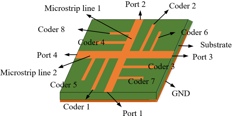
Figure 1: Physical structure.
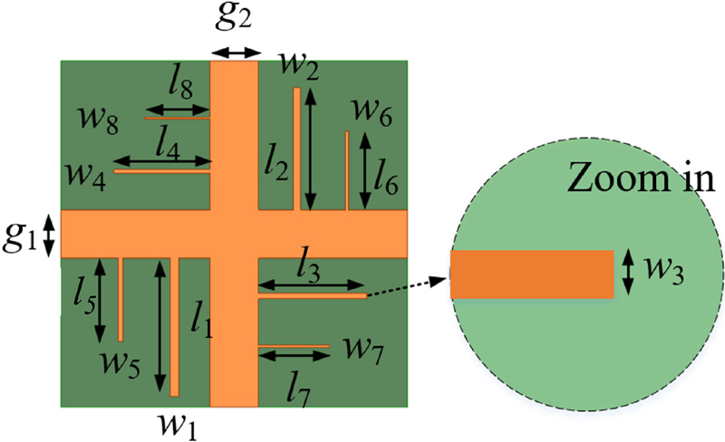
Figure 2: Top view of the tag.
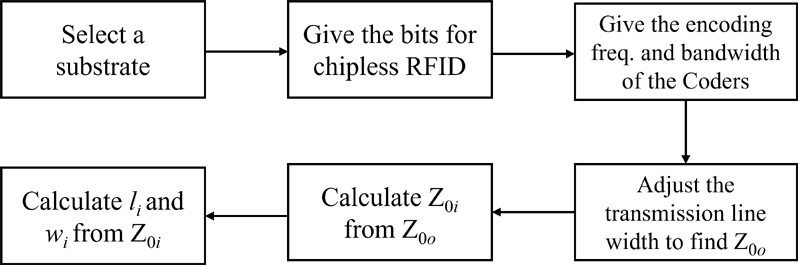
Figure 3: Calculating process for the dimensions of coders.
Note that the final length and width of the coders are obtained by optimizing these parameters through the simulations of well-known HFSS. The optimized lengths and widths w () of the eight coders are presented in Fig. 2 and their values are summarized in Table 1. Since one coder can produce one resonant frequency, eight coders can generate eight resonant frequencies with their bandwidths and they can be used to encode information when excited. The correspondence between the lengths of coders and encoding frequencies is shown in Fig. 4. In order to miniaturize the tag, we set the widths of two microstrip transmission lines as mm and mm, respectively, and set the total length and width of the tag as mm and mm, respectively. Considering the favorable properties of Rogers RTduroid 5880 tm as a dielectric medium, it is used as the substrate material in the tag and its relative permittivity, dielectric loss tangent, and thickness are , , and mm, respectively. As a high-frequency laminate used for stripline and microstrip circuit structures, Rogers RTduroid 5880 tm is a microfiber-reinforced polytetrafluoroethylene (PTFE) composite material that can maintain a consistent dielectric constant between different layers of the laminate and keep unchanged over a wide frequency range. In addition, the material has the merits of low electrical loss, low moisture absorption, and excellent chemical resistance.
Table 1: Optimized lengths and widths of the coders (Unit: mm)
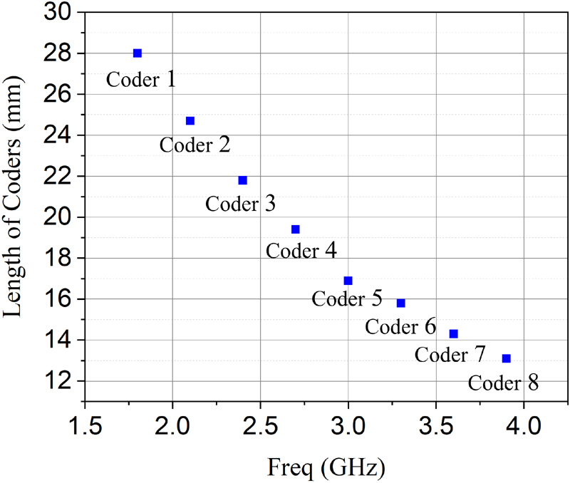
Figure 4: Lengths of coders (mm) versus encoding frequency.
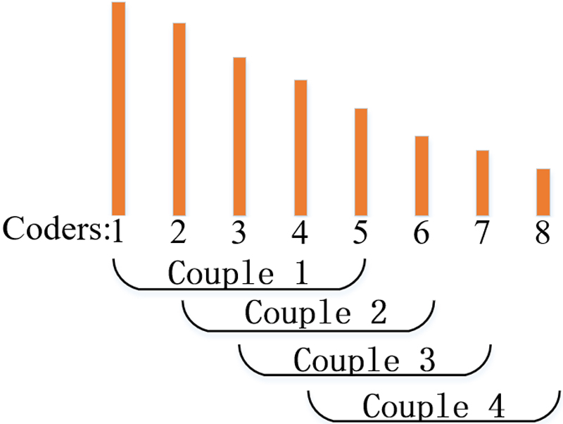
Figure 5: Coupling schematic diagram of unit coders.
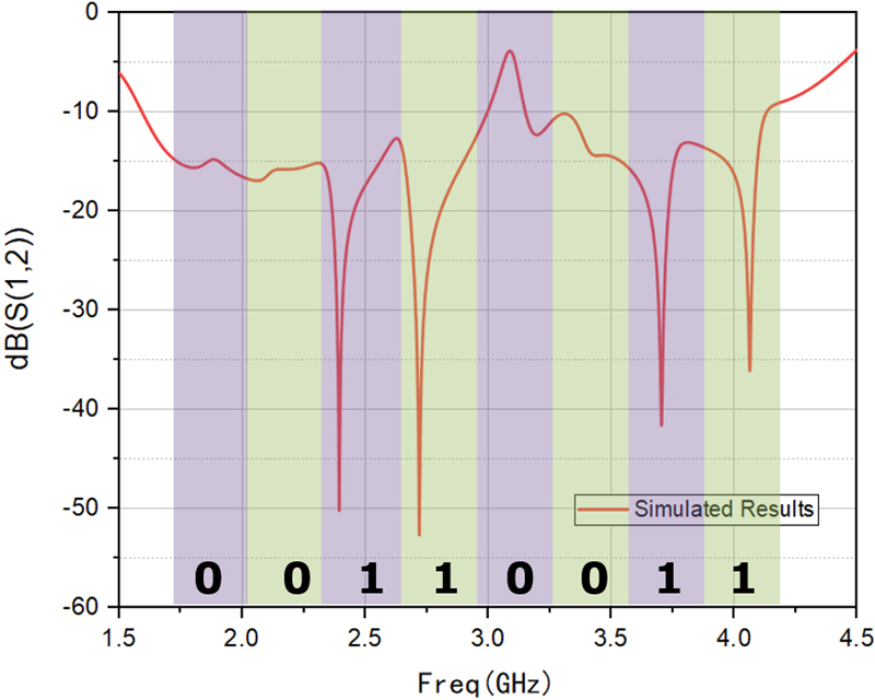
Figure 6: A coding display with the code of .
The pairing of the eight coders is illustrated in Fig. 5. Specifically, Coder is paired with Coder , Coder with Coder , Coder with Coder , and Coder with Coder , respectively. These pairings are denoted as Couple , Couple , Couple , and Couple , respectively. Such a pairing scheme can minimize the coupling interference between unit coders and waste of spectrum resource. If the coders are paired in order, for example, Coder and Coder are paired in the same microstrip line, they can easily produce a coupling interference and even cause an encoding error because the lengths of the two unit coders are close and they could produce similar resonant frequencies. On the other hand, we should minimize the frequency bandwidth in case the spectrum resource is wasted, hence the gap of neighboring resonant frequencies should not be far away excessively. As a trade-off, we select a total frequency range from to GHz as the encoding bandwidth. Eight resonant frequencies with an average interval can be obtained by selecting appropriate dimensions for the coders and they are GHz, GHz, GHz, GHz, GHz, GHz, GHz, and GHz, respectively.
To demonstrate the proposed encoding scheme, we present an example with the code of and it is shown in Fig. 6. In the figure, Code “” and Code “” are achieved in the corresponding encoding bandwidths by setting the appearance and disappearance of corresponding unit coders, respectively. The appearance of a unit coder will produce a notch in the figure and we define dB as a threshold. If the notch is below dB, then the corresponding code is designated as “”, otherwise the code is designated as “”.
IV. SIMULATED AND MEASURED RESULTS
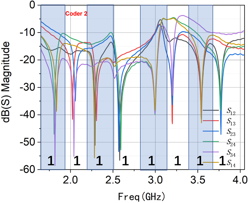
Figure 7: Port independence verification.
Figure 8 shows the fabricated tag antenna sample and the coaxial connectors are welded to four feeding ports. The tag is fabricated under laboratory conditions by the etching method which is a subtraction process [27]. In the measurement experiment, as shown in the Fig. 9, we connect the Vector Network Analyzer (VNA) with chipless RFID tag using two coaxial lines, and we measure the parameter transmission coefficient values of every two ports , , , , , . We define the number here as the port number. For example, indicates the transmission coefficient between Port and Port .
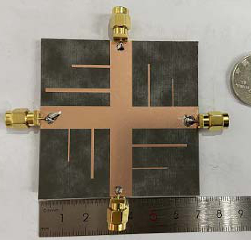
Figure 8: Fabricated tag antenna sample.
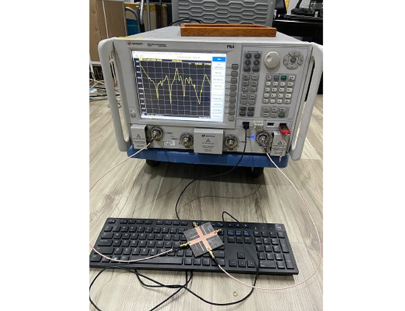
Figure 9: Photo of device connection.
To verify the independent port, all the coding cases of connecting two ports are presented, respectively. It can be seen from Fig. 7, no matter which two ports are connected, their deep notches (the coding frequencies) from attenuated frequencies are within a specific same range. Although some deep notches of coders have small deviations, they are all within the coding frequency band 1.952.25 GHz. For example, the Coder 2 deep notch has a gap of about 20 MHz between the purple curve and the blue curve, and there is also a gap of about 20 MHz between the purple curve and the red curve. But it will not affect the encoding results, and such small differences are acceptable.
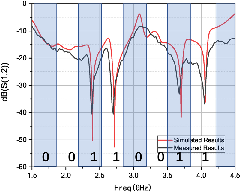
Figure 10: Transmission coefficient by connecting Port 1 and Port 2 and the code is 00110011.
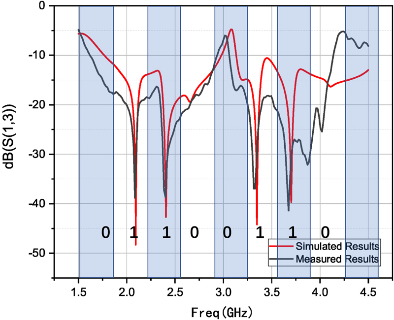
Figure 11: Transmission coefficient by connecting Port 1 and Port 3 and the code is 01100110.
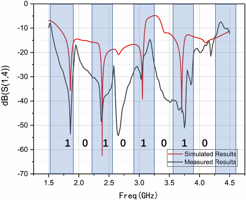
Figure 12: Transmission coefficient by connecting Port 1 and Port 4 and the code is 10101010.
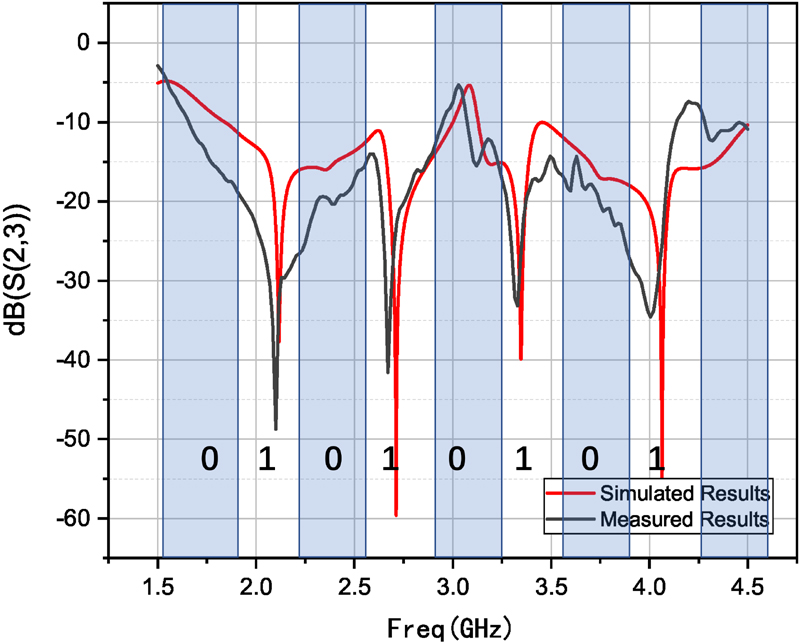
Figure 13: Transmission coefficient by connecting Port 2 and Port 3 and the code is 01010101.
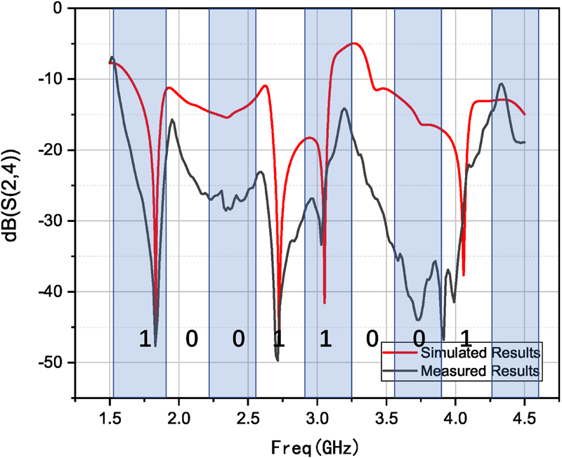
Figure 14: Transmission coefficient by connecting Port 2 and Port 4 and the code is 10011001.
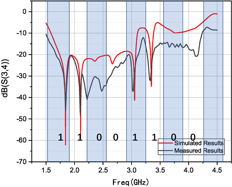
Figure 15: Transmission coefficient by connecting Port 3 and Port 4 and the code is 11001100.
The software HFSS is applied in the simulations and Fig. 10 shows the transmission coefficient of the proposed reconfigurable chipless tag. When we connect Port 1 and Port 2, the four Coders, namely, Coder , Coder , Coder , and Coder are excited, and corresponding four resonant frequencies of GHz, GHz, GHz and GHz can be obtained with the code of . At the same time, the other four coders are not influenced. So, it has a good isolation effect as well, which realize the chipless tag’s anti-interference ability. The other five codes can be obtained by connecting other ports. Those are , , , and , respectively. All of these codes are depicted in Figs. 10–15.
Traditionally, the structure of chipless RFID tag is not able to be changed after the tag being designed and fabricated and one tag can only produce one code. The proposed tag with unit coders can produce codes by connecting different ports. So only one-type tag is needed to design in actual application if we need codes. Meanwhile, the code “” or “” can be obtained in the corresponding encoding band by arranging the presence or absence of unit coders. So the proposed tag can encode -bit data. Since one -bit tag can produce codes, we only need to design electronic tags, significantly enhancing the coding capacity.
The aforementioned experiments employed a vector network analyzer of Keysight which is connected to two coaxial cables to conduct the wired measurement. For cross-validation, we performed a second set of wired measurements as shown in Fig. 16, utilizing a Rohde & Schwarz vector network analyzer and replacing the previous coaxial cables with specialized test cables designed for network analyzers. These cables have a characteristic impedance of 50 ohms, a propagation velocity of 76%, and a maximum operating frequency of 26.5 GHz. They are characterized by low insertion loss and high durability, which helps to mitigate the issue of significant measurement errors.
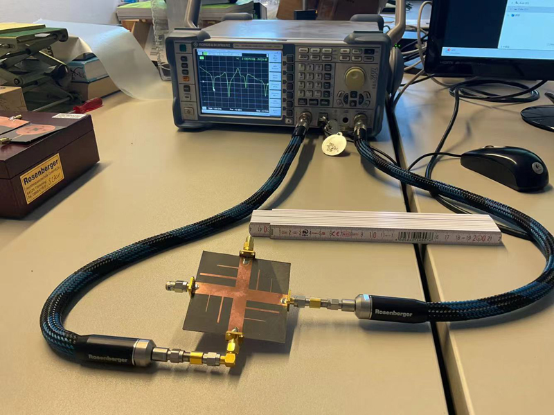
Figure 16: Wired measurement via a Rohde & Schwarz vector network analyzer.
Additionally, we conducted wireless measurements. Figure 17 illustrates the scenario of performing the wireless measurements, including two orthogonally polarized conical log-periodic antennas as the transmitting and receiving antennas, respectively. Two ultra-wideband monopole antennas are vertically integrated into the designed miniaturized tag. The conical log-periodic antennas are connected to the ports of a chipless reader to measure the transmission coefficient response of the integrated tag. The measurement distance between the antennas and tag is approximately 15 cm.
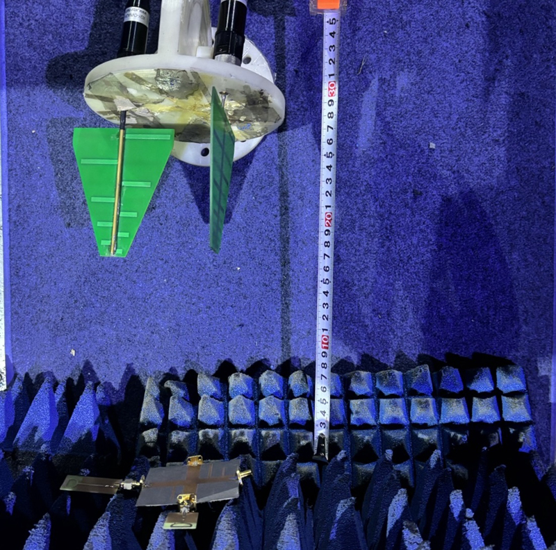
Figure 17: Scenario of performing the wireless measurement.
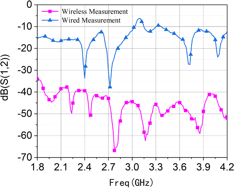
Figure 18: of wired and wireless measurement.
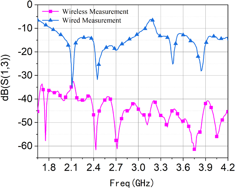
Figure 19: of wired and wireless measurement.
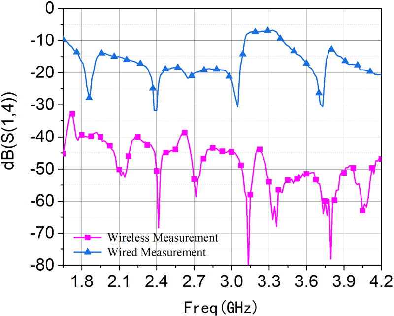
Figure 20: of wired and wireless measurement.
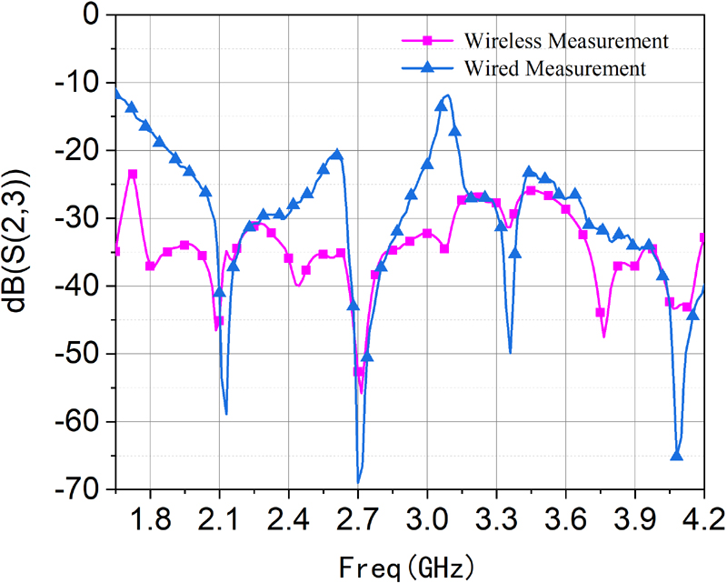
Figure 21: of wired and wireless measurement.
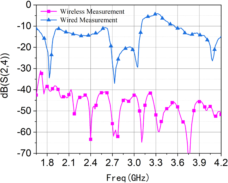
Figure 22: of wired and wireless measurement.
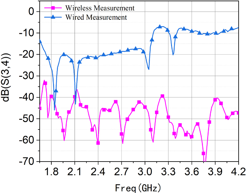
Figure 23: of wired and wireless measurement.
Figures 18–23 display the comparison between the results of the second wired measurements and the wireless measurements. The results indicate a good agreement between the wired and wireless measurement outcomes. However, due to the presence of background noise, there is a certain discrepancy between the results of the wired and wireless measurements. Additionally, some resonant points exhibit errors, possibly due to the fact that the cables and connectors used to connect the VNA and the antennas may introduce additional losses in actual measurements. These losses might not have been fully considered in the simulations, leading to discrepancies between the measured and simulated results. Particularly at high frequencies, the losses in the cables become morepronounced.
Table 2: Comparison between the proposed tag and other chipless tags
| Tag Type | Encode Density | Size () | Reconfigurability | Substrate Material | Reference |
| Re-transmission | 0.4 bit/cm | 3070 | No | SnO/G | [28] |
| RCS | 0.45 bit/cm | 2121 | No | FR-4 | [29] |
| RCS | 28.6 bit/cm | 3.54 | No | Taconic TLX-0(high cost) | [30] |
| RCS | 745.1 bit/ | 6.43.4 | Yes | Rogers RO4003 | [2] |
| Re-transmission | 0.16 bit/cm | 7070 | Yes | Rogers RT/duroid 5880 | our work |
is the guided wavelength at the lowest resonant frequency.
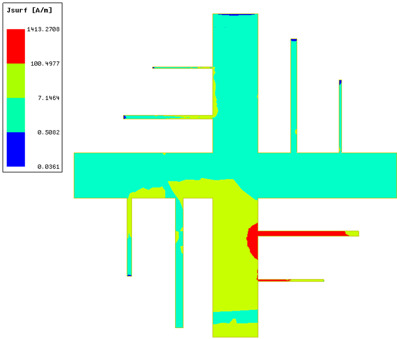
Figure 24: Surface current distribution at the frequency of GHz.
Table 2 shows the comparison of the tag we proposed in this work with other chipless tags reported. Although the proposed tag has a relatively low encoding density, it still can reduce the size of the tag compared to structures where encoding units are placed on both sides of the microstrip line. This is because our proposed structure connects the coding unit (Coder) in a clockwise rotation on the cross-microstrip line. Moreover, it possesses reconfigurability, and the material used is the commonly utilized Rogers RT/duroid 5880, which is relatively cost-effective.
The surface current distributions generate the electromagnetic signals and thus impact the coding quality. Figures 24–27 present the surface current distributions on the tag at different frequencies, where the red region represents a larger current density. From the current distributions, we can clearly see the activated states of the tag. Taking the current distribution generated for connecting ports and as an example. When we perform the parameter sweep analysis at the frequency of GHz, GHz, GHz, and GHz, respectively, we can obtain the corresponding working codes, i.e. Coder , Coder , Coder , and Coder , respectively. There should be one coder activated for each frequency theoretically and the red region indicates that the coders are strongly excited. From Figs. 24–27, we can validate this conclusion, even though there are the cases that two coders are simultaneously activated at the same frequency. However, this does not affect the other four coders, so the simultaneous activation is acceptable. Taking Fig. 27 as an example, we can see that Coder and Coder are simultaneously activated, but the encoding result remains , which is unchanged. This is because the other four coders are located at another microstrip line and they will not be affected. In addition, since the tag is fabricated using an etching method with chemical solution in a limited laboratory environment, there is a big discrepancy between the measurement results and simulation results. If we use a Laser Direct Structuring (LDS) method to fabricate the tag, the discrepancy can be greatly reduced because the LDS method can more precisely control the geometry and placement of conductive elements.
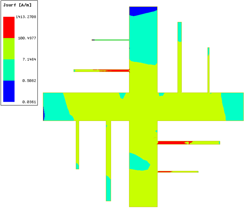
Figure 25: Surface current distribution at the frequency of GHz.
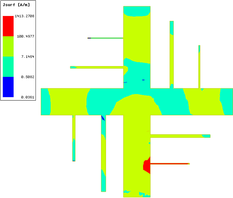
Figure 26: Surface current distribution at the frequency of GHz.
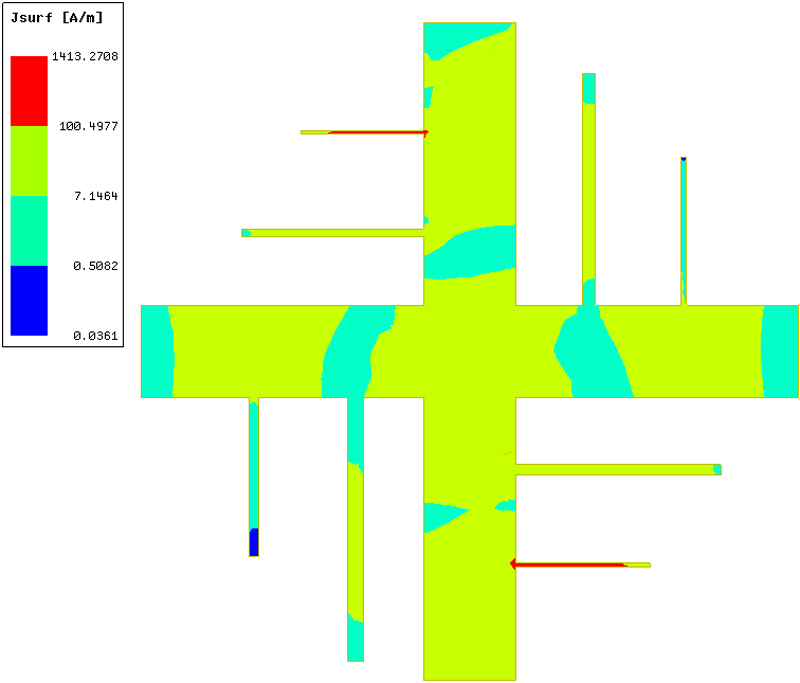
Figure 27: Surface current distribution at the frequency of GHz.
V. CONCLUSION
This paper proposes a novel reconfigurable chipless RFID tag based on a notch filter. The tag consists of four separated and noninteracted ports and the reconfigurability of encoding results is achieved by combining different ports. Also, the tag has a strong anti-interference capability because the cross-combination of unit coders is used based on their spacings. The tag can encode the information with about 8 bits by using Code “” or “” to represent the appearance or disappearance of the unit coders, respectively, and the encoding capacity can be further enhanced if using more unit coders. The tag has a compact structure whose size is only mm. The encode density of the tag are 0.16 bit/cm. We present typical encoding examples to illustrate the proposed tag and its good performance has been verified by both simulation results and measurement results.
REFERENCES
[1] S. M. Chiang, E. H. Lim, P. S. Chee, Y. H. Lee, and F. L. Bong, “Dipolar tag antenna with a top-loading inductive channel with broad range frequency tuning capability,” IEEE Transactions on Antennas and Propagation, vol. 70, no. 3, pp. 1653-1662, Mar. 2022.
[2] L. Wang, T. Liu, J. Siden, and G. Wang, “Design of chipless RFID tag by using miniaturized open-loop resonators,” IEEE Transactions on Antennas and Propagation, vol. 66, no. 2, pp. 618-626, Feb.2018.
[3] N. Javed, M. A. Azam, and Y. Amin, “Chipless RFID multisensor for temperature sensing and crack monitoring in an IOT environment,” IEEE Sensors Letters, vol. 5, no. 6, pp. 1-4, June 2021.
[4] L. Corchia, G. Monti, E. D. Benedetto, and L. Tarricone, “A chipless humidity sensor for wearable applications,” in IEEE International Conference on RFID Technology and Applications, Pisa, Italy, Sep. 2019.
[5] A. M. J. Marindra and G. Y. Tian, “Chipless RFID sensor tag for metal crack detection and characterization,” IEEE Transactions on Microwave Theory and Techniques, vol. 66, no. 5, pp. 2452-2462, May 2018.
[6] L. Y. Liu, A. K. Poddar, U. L. Rohde, and M. S. Tong, “A novel flexible chipless RFID tag sensor for monitoring environmental humidity,” IEEE Sensors Journal, vol. 23, no. 24, pp. 31237-31249, Dec. 2023.
[7] Y. Gao, M. Mahmoodi, and R. Zoughi, “Design of a novel frequency-coded chipless RFID tag,” IEEE Open Journal of Instrumentation and Measurement, vol. 1, pp. 1-9, 2022.
[8] M. Noman, U. A. Haider, A. M. Hashmi, H. Ullah, A. I. Najam, and F. A. Tahir, “A novel design methodology to realize a single byte chipless RFID tag by loading a square open-loop resonator with micro-metallic cells,” IEEE Journal of Microwaves, vol. 3, no. 1, pp. 43-51, Jan. 2023.
[9] M. T. Tu, P. Cheong, and W. W. Choi, “Defected ground structure with half-wavelength spiral resonator of ultrawide band chipless RFID tag,” IEEE Journal of Radio Frequency Identification, vol. 3, no. 3, pp. 121-126, Sep. 2019.
[10] A. Vena, A. A. Babar, L. Sydänheimo, M. M. Tentzeris, and L. Ukkonen, “A novel near-transparent ask-reconfigurable inkjet-printed chipless RFID tag,” IEEE Antennas and Wireless Propagation Letters, vol. 12, pp. 753-756, 2013.
[11] M. S. Reynolds, “A 500C tolerant ultra-high temperature 2.4 GHz 32 bit chipless RFID tag with a mechanical BPSK modulator,” in 2017 IEEE International Conference on RFID (RFID), Phoenix, AZ, pp. 144-148, 2017.
[12] B. Kubina, M. Schusler, C. Mandel, A. Mehmood, and R. Jakoby, “Wireless high-temperature sensing with a chipless tag based on a dielectric resonator antenna,” in SENSORS, 2013 IEEE, Baltimore, MD, pp. 1-4, 2013.
[13] V. P. Plessky, W. Steichen, S. Harma, and C. S. Hartmann, “PS-1 SAW RFID tag with reduced size,” in 2006 IEEE Ultrasonics Symposium, Vancouver, BC, Canada, pp. 2389-2392, 2006.
[14] A. Chamarti and K. Varahramyan, “Transmission delay line based ID generation circuit for RFID applications,” IEEE Microwave and Wireless Components Letters, vol. 16, no. 11, pp. 588-590, Nov. 2006.
[15] M. Donelli, “A chipless RFID system based on substrate impedance waveguide resonators (SIW),” in 2017 IEEE-APS Topical Conference on Antennas and Propagation in Wireless Communications (APWC), Verona, Italy, pp. 29-32, 2017.
[16] C. Feng, X. Chen, L. Han, L. Li, G. Han, and W. Zhang, “Angle-based Y-shaped chipless radio frequency identification tag,” IET Microwaves Antennas and Propagation, vol. 9, no. 15, pp. 1778-1785, Dec. 2015.
[17] Y. J. Zhang, R. X. Gao, Y. He, and M. S. Tong, “Effective design of microstrip-line chipless RFID tags based on filter theory,” IEEE Transactions on Antennas and Propagation, vol. 67, no. 3, pp. 1428-1436, Nov. 2019.
[18] L. Zhang, H. H. Su, and M. S. Tong, “A novel design of surface acoustic wave-based chipless radio frequency identification tag based on multiphysics modeling,” International Journal of Numerical Modelling: Electronic Networks, Devices and Fields, vol. 34, no. 6, pp. 1-10, Oct.2021.
[19] Q. Gu, G. C. Wan, C. Gao, and M. S. Tong, “Frequency-coded chipless RFID tag based on spiral resonators,” in 2016 Progress in Electromagnetics Research Symposium (PIERS), Shanghai, China, pp. 844-846, 2016.
[20] G. C. Wan, Q. Gu, X. R. Zhang, and M. S. Tong, “Frequency-coded chipless RFID tag based on hybrid coding technique,” in 2017 IEEE International Symposium on Antennas and Propagation & USNC/URSI National Radio Science Meeting, San Diego, CA, USA, pp. 2519-2520, 2017.
[21] G. C. Wan, Y. K. Kuang, Q. Xu, and M. S. Tong, “A novel chipless RFID tag based on backscattering principle,” in 2018 Progress in Electromagnetics Research Symposium (PIERS-Toyama), Toyama, Japan, pp. 1295-1298, 2018.
[22] X. Y. Guo, G. C. Wan, Y. M. Gao, and M. S. Tong, “A novel temperature sensor based on chipless RFID tags,” in 2020 IEEE MTT-S International Conference on Numerical Electromagnetic and Multiphysics Modeling and Optimization (NEMO), Hangzhou, China, pp. 1-3, 2020.
[23] L. Zhang, M. M. Li, and M. S. Tong, “A chipless ultra-wideband RFID tag based on cylindrical dielectric resonator,” in 2021 IEEE International Symposium on Antennas and Propagation and USNC-URSI Radio Science Meeting (APS/URSI), Singapore, Singapore, pp. 381-382, 2021.
[24] J. Li, L. Shi, X. Jin, Q. Zhang, Y. Ran, Q. Lei, Y. Ma, Y. Liu, J. Xiao, and J. Wang, “Efficient and explicit Fourier modal method for ultrathin metallic gratings,” Chinese Journal of Electronics, vol. 31, no. 6, pp. 1155-1160, Nov. 2022.
[25] C. Jia, Z. He, D. Ding, L. Guan, X. Ai, J. Liu, and X. Chen, “Characteristic mode analysis for thin dielectric sheets with alternative surface integral equation,” Chinese Journal of Electronics, vol. 31, no. 6, pp. 1181-1188, Nov. 2022.
[26] I. Hunter, Theory and Design of Microwave Filters, London, U.K.: IET, 2001.
[27] J. Birkenshaw, Printed Electronics. Surrey: Pira International, 2004.
[28] B. Tao, L. Feng, F. Miao, and Y. Zang, “High sensitivity chipless RFID humidity sensor tags are based on SnO/G nanomaterials,” Vacuum, vol. 202, p. 111126, Aug. 2022.
[29] P. P. Sahu, D. P. Mishra, T. K. Das, and S. K. Behera, “Design of a chipless RFID tag for 2.4 GHz and 5.8 GHz ISM band applications,” in 2020 IEEE International Students’ Conference on Electrical, Electronics and Computer Science (SCEECS), Bhopal, India, pp. 1-4, 2020.
[30] O. Necibi, S. Naoui, and A. Gharsallah, “Design of a chipless RFID tag based on the frequency shift technique for K band,” in 2016 2nd International Conference on Advanced Technologies for Signal and Image Processing (ATSIP), Monastir, Tunisia, pp. 816-819, 2016.
BIOGRAPHIES

Li Zhang received the B.S. degree in information and computer science from Henan Agriculture University, Zhengzhou, China, in 2008, and the M.S. degree in electronic science and technology from Tongji University, Shanghai, China, in 2015. Since 2019, she started to pursue the Ph.D. degree in electronic science and technology, Tongji University, Shanghai, China, and is expected to receive the Ph.D. degree in January 2025. From September 2022 to September 2024, She was a visiting/exchange Ph.D. Student with the Technical University of Munich, Munich, Germany. Her current research interests include antenna technology and computational electromagnetics. Ms. Zhang was a recipient of the China Scholarship Council in 2021 and the National Scholarship in 2022.

Ajay K. Poddar is an IEEE Fellow and member of IEEE Eta-Kappa-Nu, has been working as a Chief Scientist at Synergy Microwave, NJ, USA, for the last 23 years, responsible for the design and development of signal generation and signal processing electronics, RF-MEMS, and Metamaterial-Sensors/Electronics for industrial, medical, space applications. He is also a visiting professor at the University Of Oradea, Romania, Indian Institute of Technology Jammu, India, and a guest lecturer at the Technical University Munich, Germany. Previously (1991-2001), he was a Senior Scientist and Program Manager at DRDO (Defense Research and Development Organization), Ministry of Defense, India, and a visiting Professor at the University of Pune, India. Dr. Poddar graduated from IIT-Delhi, India; his Doctorate (Dr.-Ing.) from Technical University Berlin, Germany; Post Doctorate (Dr.-Ing. habil) from Brandenburg Technical University Cottbus, Germany. He has received over a dozen awards, to name a few 2015 IEEE IFCS Cady Award in recognition of his outstanding scientific contributions to a host of frequency-generating and frequency-controlled electronics and timing devices for industrial, medical, and space applications, and recipient of the 2018 IEEE MGA Innovation Award for his dedicated volunteering service to members, chapters and humanitarian projects, recipient 2015 IEEE R1 Award for “Outstanding Scientific Contributions, Leadership and Service”, recipient 2009 IEEE R1 Award for “Outstanding Leadership and Contributions in the Research, Design, and Development of Microwave Systems”, and selected in the list of Divine Innovator “Divine Innovation: 10 Technologies Changing the Future of Passive and Control Components” (Photo shows on Cover page, Microwave Journal, November 2011). Recently, Dr. Poddar received the 2023 RCA Armstrong Medal Award for his three decades of scientific research work in signal generation and signal processing electronics for the application in modern radios and test and measurement equipment. Dr. Poddar published 350 plus scientific papers in journals, magazines, and conference proceedings, co-authored six technical books/chapters, and 40 plus patents for scientific and technological innovations. For the past 30 years, he has supervised many PhD students worldwide, served as an Editor of many Technical Journals, and currently serving in several scientific committees, professional societies, and voluntary organizations.

Ulrich L. Rohde is a Partner of Rohde & Schwarz, Munich Germany; Chairman of Synergy Microwave Corp., Paterson, New Jersey; President of Communications Consulting Corporation; serving as an honorary member of the Senate of the University of the Armed Forces Munich, Germany, honorary member of the Senate of the Brandenburg University of Technology Cottbus–Senftenberg, Germany. Dr. Rohde is serving as a full Professor of Radio and Microwave Theory and Techniques at the University of Oradea and several other universities worldwide, to name a few: Honorary Professor IIT-Delhi, Honorary Chair Professor IIT-Jammu, Professor at the University of Oradea for microwave technology, an honorary professor at the BTU Cottbus-Senftenberg University of Technology, and professor at the German Armed Forces University Munich (Technical Informatics). Rohde has published 400+ scientific papers, co-authored over dozen books, with John Wiley and Springer, and holds 50 plus patents; received several awards, to name a few recent awards: recipient of 2023 IEEE Communications Society Distinguished Industry Leader Award, 2023 IEEE Antennas and Propagation Society Distinguished Industry Leader Award, 2022 IEEE Photonics Society Engineering Achievement Award, 2021 Cross of Merit of the Federal Republic of Germany, 2020 IEEE Region 1 Technological Innovation Award, 2019 IETE Fellow Award, 2019 IEEE CAS Industrial Pioneer Award; 2017 RCA Lifetime achievement award, 2017 IEEE-Cady Award, 2017 IEEE AP-S Distinguish achievement award, 2017 Wireless Innovation Forum Leadership Award, 2016 IEEE MTT-S Applications Award, 2015 IEEE-Rabi Award, 2015 IEEE Region-1 Award, and 2014 IEEE-Sawyer Award. Dr. Ulrich Rohde is the recipient of the “2021 Cross of Merit of the Federal Republic of Germany”. The Order of Merit of the Federal Republic of Germany, also known as the Federal Cross of Merit, is the highest tribute the Federal Republic of Germany can pay to individuals for services to the nation. In December 2022, The Indian National Academy of Engineering (INAE) inducted Dr. Ulrich Rohde as a fellow during ceremonies for “outstanding contributions to engineering and also your dynamic leadership in the engineering domain, which has immensely contributed to the faster development of the country.” Dr. Rohde is only the third foreign fellow elected by the INAE, preceded by Dr. Jeffrey Wineland, who won a Nobel Prize in Physics.

Mei Song Tong received the B.S. and M.S. Degrees from Huazhong University of Science and Technology, Wuhan, China, respectively, and Ph.D. degree from Arizona State University, Tempe, Arizona, USA, all in electrical engineering. He is currently the Distinguished Professor and Head of Department of Electronic Science and Technology, and Vice Dean of College of Microelectronics, Tongji University, Shanghai, China. He has also held an adjunct professorship at the University of Illinois at Urbana-Champaign, Urbana, Illinois, USA, and an honorary professorship at the University of Hong Kong, China. He has published more than 700 papers in refereed journals and conference proceedings and co-authored 8 books or book chapters. His research interests include electromagnetic field theory, antenna theory and design, simulation and design of RF/microwave circuits and devices, interconnect and packaging analysis, inverse electromagnetic scattering for imaging, and computational electromagnetics. Prof. Tong is a Fellow of the Electromagnetics Academy, Fellow of the Japan Society for the Promotion of Science (JSPS), and Senior Member (Commission B) of the USNC/URSI. He has been the chair of Shanghai Chapter since 2014 and the chair of SIGHT committee in 2018, respectively, in IEEE Antennas and Propagation Society. He has served as an associate editor or guest editor for several well-known international journals, including IEEE Antennas and Propagation Magazine, IEEE Transactions on Antennas and Propagation, IEEE Transactions on Components, Packaging and Manufacturing Technology, International Journal of Numerical Modeling: Electronic Networks, Devices and Fields, Progress in Electromagnetics Research, and Journal of Electromagnetic Waves and Applications, etc. He also frequently served as a session organizer/chair, technical program committee member/chair, and general chair for some prestigious international conferences. He was the recipient of a Visiting Professorship Award from Kyoto University, Japan, in 2012, and from University of Hong Kong, China, 2013. He advised and coauthored 15 papers that received the Best Student Paper Award from different international conferences. He was the recipient of the Travel Fellowship Award of USNC/URSI for the 31th General Assembly and Scientific Symposium (GASS) in 2014, Advance Award of Science and Technology of Shanghai Municipal Government in 2015, Fellowship Award of JSPS in 2016, Innovation Award of Universities’ Achievements of Ministry of Education of China in 2017, Innovation Achievement Award of Industry-Academia-Research Collaboration of China in 2019, “Jinqiao” Award of Technology Market Association of China in 2020, Baosteel Education Award of China in 2021, Carl Friedrich von Siemens Research Award of the Alexander von Humboldt Foundation of Germany in 2023, and Technical Achievement Award of Applied Computational Electromagnetic Society (ACES) of USA in 2024. In 2018, he was selected as the Distinguished Lecturer (DL) of IEEE Antennas and Propagation Society for 2019-2022.
ACES JOURNAL, Vol. 39, No. 9, 801–813
doi: 10.13052/2024.ACES.J.390906
© 2024 River Publishers