A Low-profile Wideband Pattern Reconfigurable Antenna with Metasurface
GuangRui Liu, Cheng Ju, Zijie Li, Zhiqun Yang, Xiaoyun Qu, Na Liu,and Wei-hua Zong
1College of Electronics and Information
Qingdao University, Qingdao, 266000, China
liu-guang-rui@qq.com, jucheng719@qdu.edu.cn, lizijie@qdu.edu.cn, liunana@qdu.edu.cn, weihuazong@126.com
2Shandong Institute of Space Electronic Technology
Yantai, 264003, China
yyangzq@163.com, selina.qu@163.com
Submitted On: November 28, 2023; Accepted On: May 20, 2024
ABSTRACT
This paper presents a pattern reconfigurable antenna with low-profile and wide bandwidth. The antenna is composed of a patch layer, a metasurface (MS) layer, and a full ground plane. The radiation patch consists of a microstrip-fed square and three parasitic patches. The MS with 44 units is added on the top of the patch layer to improve bandwidth as well as tune radiation pattern. Ten of the MS units are available to connect with the ground plane, each of which is loaded with a PIN diode to control the shorting state, providing 12 beam states with reconfigurable beams between 5 to 15 both in xoz and yoz planes. The proposed antenna has been fabricated and measured. Measurement shows that the antenna has a wide impedance bandwidth of 4.02-5.72 GHz, a beam scanning range of -16-15 in xoz plane and -13-15 in yoz plane, peak gain range of 4.94-6 dBi. With a planar shape of low profile and full ground plane, the antenna design is a good candidate to be applied in wireless communication systems with conductive surface.
Index Terms: 5G antenna, low-profile, metasurface (MS), pattern reconfigurable antenna, wideband antenna, WLAN antenna.
I. INTRODUCTION
Pattern reconfigurable antennas have the capability to reconfigure radiation patterns to satisfy the requirements from communication systems of transmission efficiency improvement, transmission interference reduction and transmission quality enhancement. These kinds of antennas have found applications in the fields of vehicle communication, the Internet of Things, etc. [1–5].
The phased array antenna, although an effective approach for pattern reconfiguration, comes with bulk volume, high cost, and realizes beam pointing control through the integration of antenna elements, phase shifters, power splitters, and feed networks. Introducing liquid crystal [6] or liquid metal [7] to tune material’s permittivity or reshape the antenna’s structure can also obtain pattern reconfiguration, however these methods involve difficulties of fast tuning as well as low efficiency.
Electrically controlling an antenna beam based on PIN diodes [8–23] offer advantages of fast modulation speed and compact structure which is desired in low-cost communication terminals. In these antennas, those with full ground plane [10–21] have virtues of good directivity and high gain. They are also immune to influence when mounted on conductive surfaces, such as vehicles, aircrafts, metallic walls, human bodies, etc. Therefore, antennas with full ground plane are more appealing in practical applications. Nevertheless, planar antennas with full ground plane come usually with narrow bandwidth [10–13]. Introducing an air gap [14–21] between ground plane and radiation patch is a commonly used solution to reduce the ground plane’s influence. However increased height may bring instability problems and the inconvenience of being mounted on and conformal with the antenna supporter. Metasurface (MS) has been adopted in antenna configuration to improve bandwidth and reduce coupling with low profile [24–29], whereas pattern reconfiguration is unavailable in these antennas.
This paper aims to improve the bandwidth of pattern reconfigurable antenna considering low profile. A patch antenna with full ground plane is chosen as the driven element. Antenna bandwidth is improved by adding MS on top of the antenna. Some MS units are controlled by PIN diodes to connect/disconnect with the ground plane to obtain 12 reshaped patterns.
II. ANTENNA CONFIGURATION AND OPERATION STATES
Figure 1 shows configuration of the proposed antenna. The antenna consists of three layers, a full ground plane at the bottom, radiation patches in the middle layer, and a MS as the top layer. The radiation patches are composed of a square patch directedly fed by a step shaped microstrip line and three parasitic patches. The MS with 44 squares is adopted to obtain wideband impedance matching as well as pattern reconfiguration. Ten of the MS units are connected with the ground plane through via holes. Each via holes pad inside the MS unit is split with other parts of the unit by slits and loaded with a PIN diode to connect the via hole. Therefore, each unit can be controlled shorted/open with the ground plane to obtain pattern reconfiguration. Two FR4 boards each with a 1.5 mm thickness, a relative permittivity of 4.4 and a relative loss tangent value of 0.02 are used as substrates. The lumped components of each PIN diode’s DC bias network are L1=L2=15 nH, L3=2.2 nH, R=200 , and C=10 pF. The antenna dimensions are listed in Table 1. The PIN diodes used in this design are of Infineon BAR64-02V.
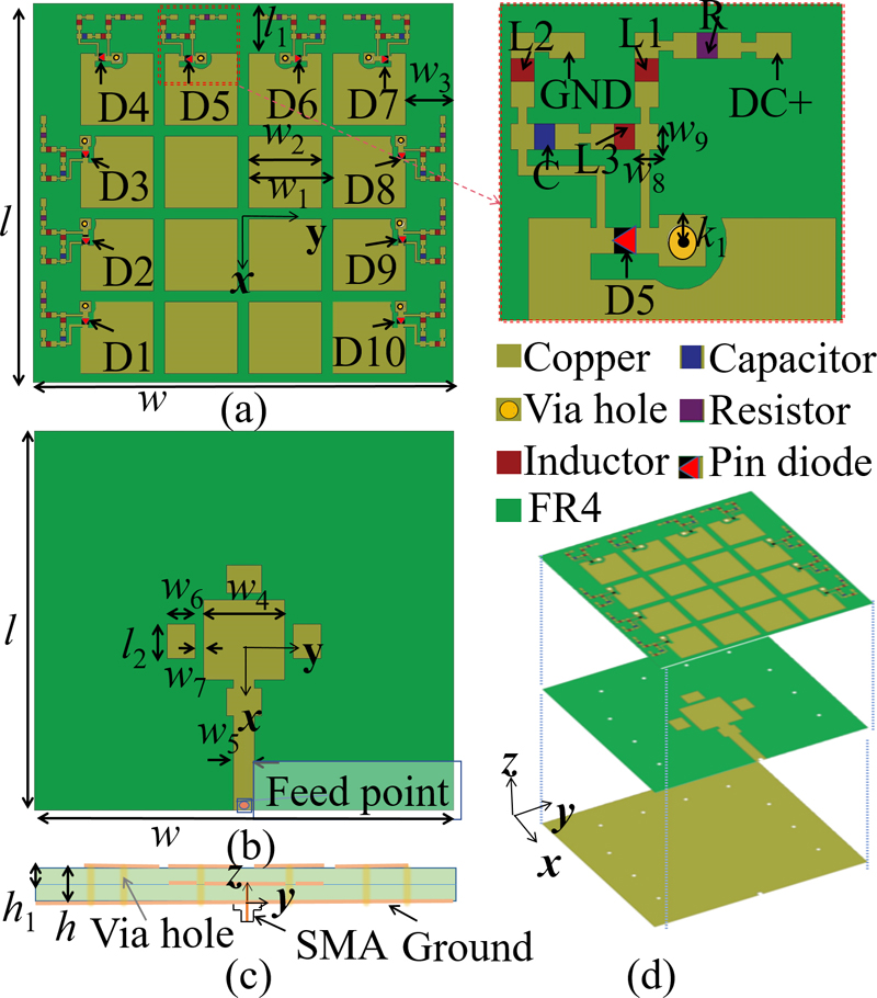
Figure 1: Configuration of the proposed antenna: (a) top layer, (b) middle layer, (c) side view, and (d) 3D-view.
Table 1: Dimensions of the proposed antenna
| Par. | Value (mm) | Par. | Value (mm) | Par. | Value (mm) |
| w | 60 | l | 55 | h | 3 |
| w | 12 | l | 7.3 | h | 1.5 |
| w | 10.4 | l | 5 | k | 0.5 |
| w | 6.8 | w | 4 | w | 0.8 |
| w | 11.6 | w | 1.2 | ||
| w | 3 | w | 0.83 |
The proposed antenna can operate at 12 states with different beam directions listed in Table 2. In this table, the binary numbers in the second column refer to each PIN diode’s working state: “1” means the PIN diode is turned on, and “0” means off. As shown in Table 2, the proposed antenna’s beam can be steadily tuned from 5 to 15 with a step of 5, both in xoz (=0) and yoz (=90) planes. Figure 2 illustrates the radiation patterns of four typical operating states.
Table 2: Operating states of the proposed antenna at 5 GHz
| State | D1-D10 | Beam(, ) | MaxGain (dBi) |
| S1 | 0001111000 | = +14 in xoz plane | 7.41 |
| S2 | 1111000000 | = +15 in yoz plane | 6.36 |
| S3 | 1100000011 | = -14 in xoz plane | 5.66 |
| S4 | 0000001111 | = -16 in yoz plane | 5.99 |
| S5 | 0001001000 | = +7 in xoz plane | 7.08 |
| S6 | 0101000000 | = +9 in yoz plane | 6.47 |
| S7 | 1000000001 | = -8 in xoz plane | 6.13 |
| S8 | 0000001010 | = -9 in yoz plane | 6.16 |
| S9 | 0010000100 | = +5 in xoz plane | 6.70 |
| S10 | 0110000000 | = +5 in yoz plane | 6.55 |
| S11 | 0100000010 | = -5 in xoz plane | 6.42 |
| S12 | 0000000110 | = -5 in yoz plane | 6.46 |
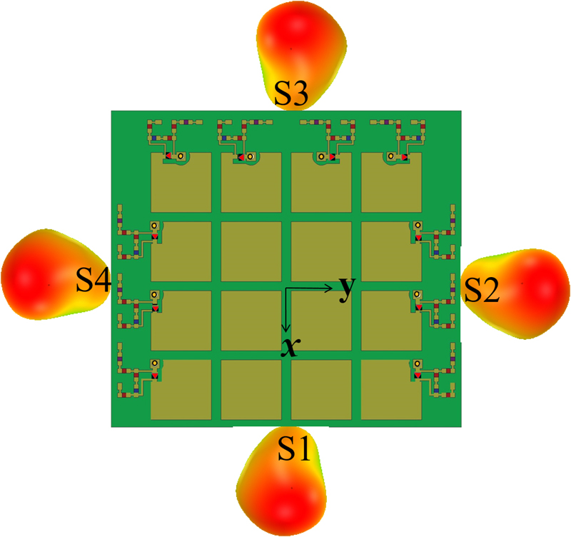
Figure 2: Simulated 3-D radiation patterns for the proposed antenna at 5 GHz.
III. ANTENNA DESIGN AND ANALYSIS
A. Antenna configuration design
Simulations are performed using the EM field simulator ANSYS High Frequency Simulation Software (HFSS). The antenna design was conducted initially from bandwidth enhancement without considering beam reconfiguration. Figure 3 shows the design evolution with three reference antennas, and Fig. 4 gives simulated S of these antennas. As shown in Fig. 3 (a), ANT-1 is a traditional square-shaped patch antenna fed with a microstrip line. As shown in Fig. 4, ANT-1 excites the first resonance at 6.37 GHz which is traditionally a quarter wavelength resonance. By adding a MS layer on the top of ANT-1’s patch layer, ANT-2’s first resonance drops to 4.15 GHz, and a second resonance is excited at 4.91 GHz, which results in an improved bandwidth of 3.98-5.18 GHz. Based on ANT-2, three parasite patches are added around the driven patch, and the feedline is modified to a step shape forming ANT-3. As shown in Fig. 4, ANT-3 excites three resonances (4.53, 5.26, 5.67 GHz) below 6 GHz, resulting in wider bandwidth of 3.96-5.78 GHz. Figure 5 illustrates the 3-D radiation pattern of ANT-3 at 5 GHz. As shown, ANT-3 has a bore-sight maximum radiation pattern with a peak gain of 6.56 dBi.
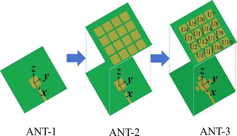
Figure 3: Antenna configuration design evolution.
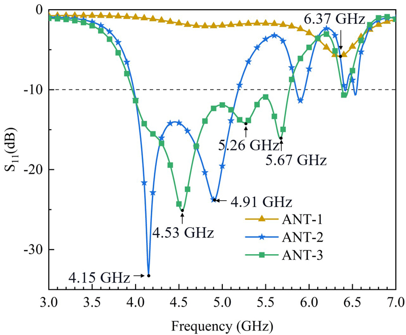
Figure 4: Simulated S of reference antennas.
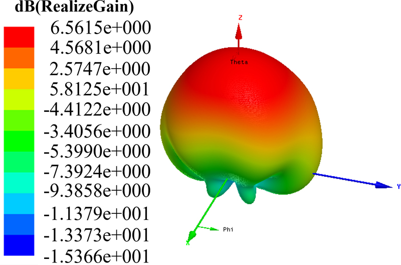
Figure 5: Simulated 3-D radiation pattern of ANT-3 at 5 GHz.
B. Mechanism of pattern reconfiguration
Based on the configuration of ANT-3, each MS unit tried to connect with the ground plane through a via hole to obtain titled radiation beam. The shorting position was arranged at the corner of each unit to reduce the influence on antenna bandwidth. Figure 6 illustrates radiation patterns and current distributions of ANT-3 with some MS units shorted. As shown in Fig. 6 (a), when only one unit (U1) is shorted, the current distributions on U1 becomes weaker than those on other units. This means that electromagnetic fields induced by U1 is bounded in the near region with little radiating to the far region which results in a tilted radiation pattern with main beam at =5, =120. As shown in Fig. 6 (b), when four MS units at the left side (U1, U2, U3, and U4) are shorted, a larger tilted beam (=15, =90) is obtained. Similar approach is also presented in [30,31] which added shorting pins to the parasitic patches on the same layer with the driven patches. To the authors’ best knowledge, it’s the first time shorting pins were added on the MS patches which are in a different layer with the radiation patch to tune radiation patterns.
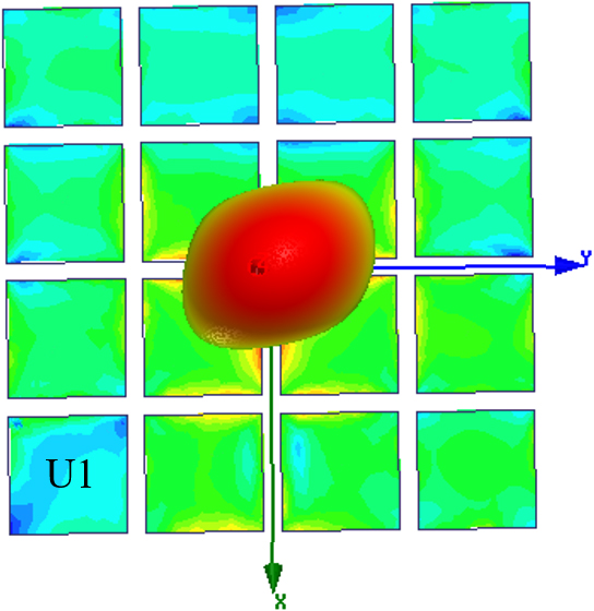
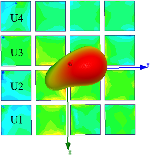
Figure 6: Simulated current distributions and radiation patterns of ANT-3 with some MS units shorted.
Theoretically, each of the 16 units can be tuned with shorted/open with ground plane forming 2 reconfigurable patterns. Nevertheless, not all the patterns are reasonable for engineering application, and the convenience of installing PIN diodes and DC bias network in the design needs also be considered. Therefore, we chose the 10 units (U1-U10) located at three edges to form 12 working states with reconfigurable patterns.
C. DC bias network and pattern reconfiguration realization
To electrically control each MS unit shorted/open with the ground plane, slits are etched around each via hole with loading a PIN diode. The DC bias network to power each PIN diode is shown in Fig. 1, which is similar with the one in [32]. The antenna’s operation states are given in Table 2.
Figure 7 shows simulated S of the proposed antenna at six states (S1, S2, S5, S6, S9, S10). As shown, the proposed antenna has similar bandwidth with ANT-3 at these six states. The other six states (S3, S4, S7, S8, S11, S12) have similar S plots with the former ones which are not included in the figures. The common bandwidth for the 12 states is 3.96-5.78 GHz.
Figures 8 and 9 illustrate simulated patterns in xoz and yoz planes at 5 GHz, respectively. As shown in Fig. 8, the proposed antenna achieves titled beams in xoz plane at =14, =-14, =+7, =-8, =+5, and =-5 at S1, S3, S5, S7, S9, and S11 states. Figure 9 shows that the antenna achieves titled beams in yoz plane at =15, =-16, =+8, =-9, =+5, and =-5 at S2, S4, S6, S8, S10, and S12 states.
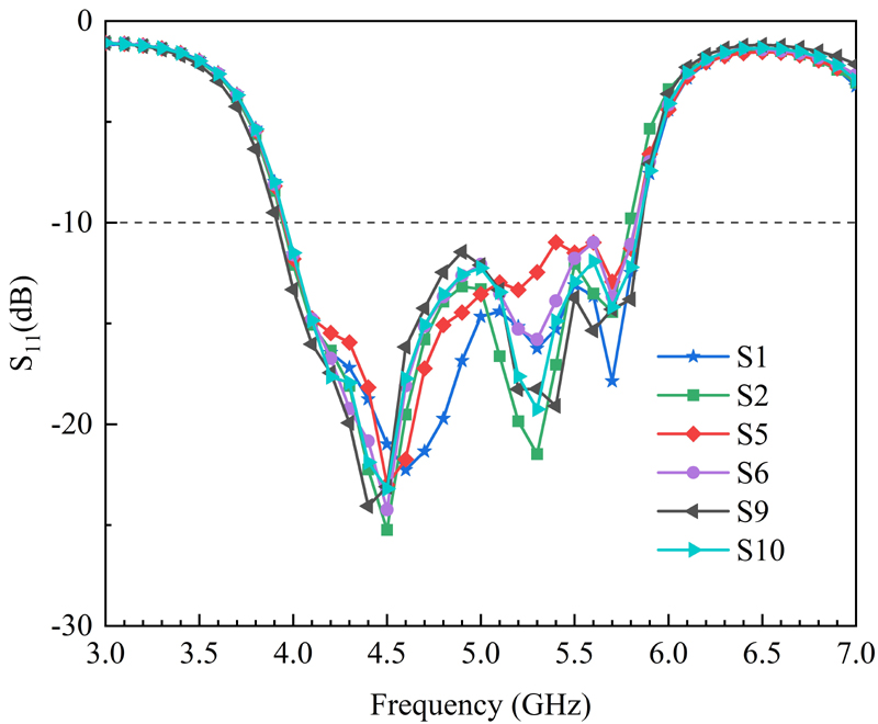
Figure 7: Simulated S of the proposed antenna.
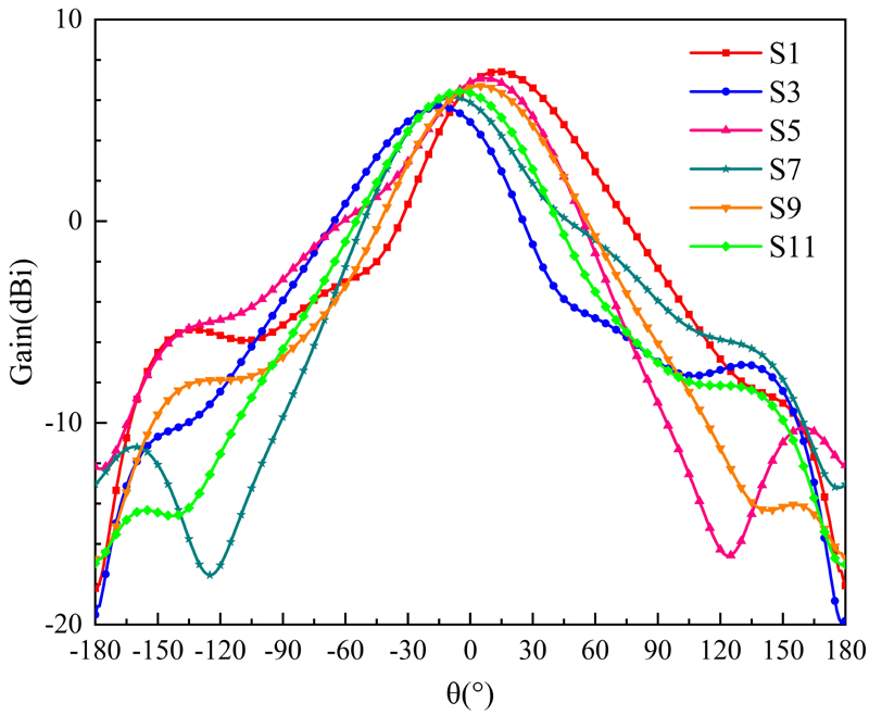
Figure 8: Simulated radiation pattern in xoz plane at 5 GHz.
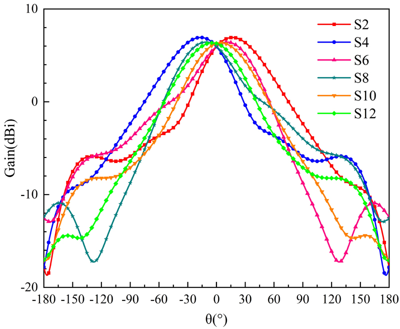
Figure 9: Simulated radiation pattern in yoz plane at 5 GHz.
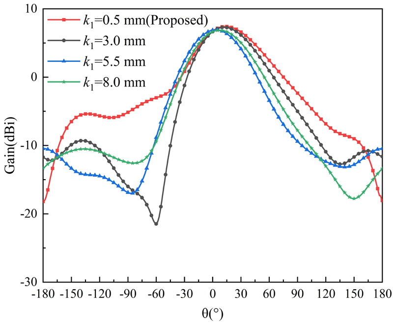
Figure 10: Simulated radiation pattern in the xoz plane at State 1 varying with k.
The positions of the PIN diodes and the shape of the slit have been optimized to reduce the influence on antenna’s pattern. Figure 10 shows simulated pattern in the xoz plane at state 1 varying with k(the position of each via hole). As shown, smaller kresults in higher gain. The value of kis set as 0.5 mm to provide enough area to contain a via hole.
IV. RESULTS AND DISCUSSION
The proposed antenna has been fabricated and measured. Figure 11 shows a photograph of the fabricated antenna, in which each PIN diode is powered by a button battery assembled in a battery container.
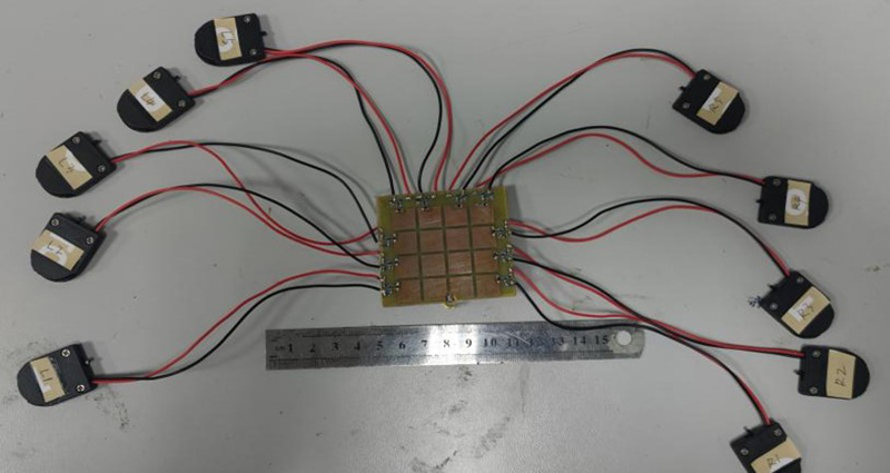
Figure 11: Photograph of the fabricated antenna.
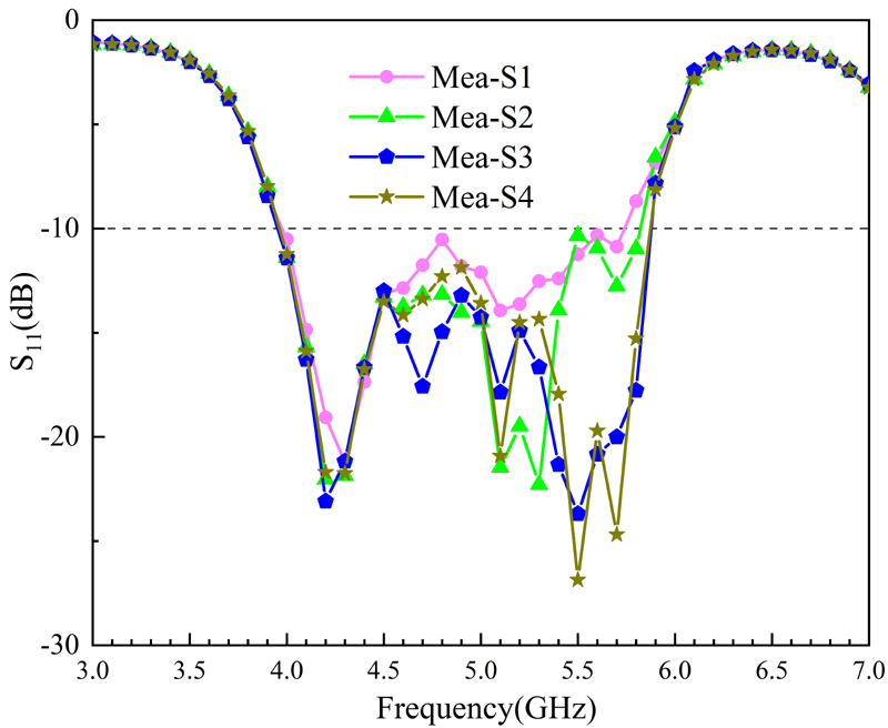
Figure 12: Measured S of the proposed antenna.
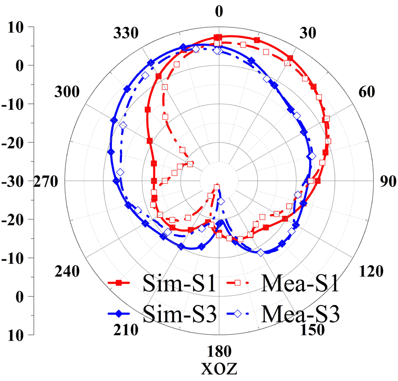
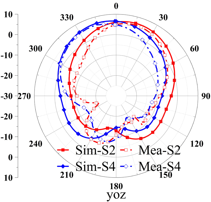
Figure 13: Measured radiation pattern at 4.8 GHz.
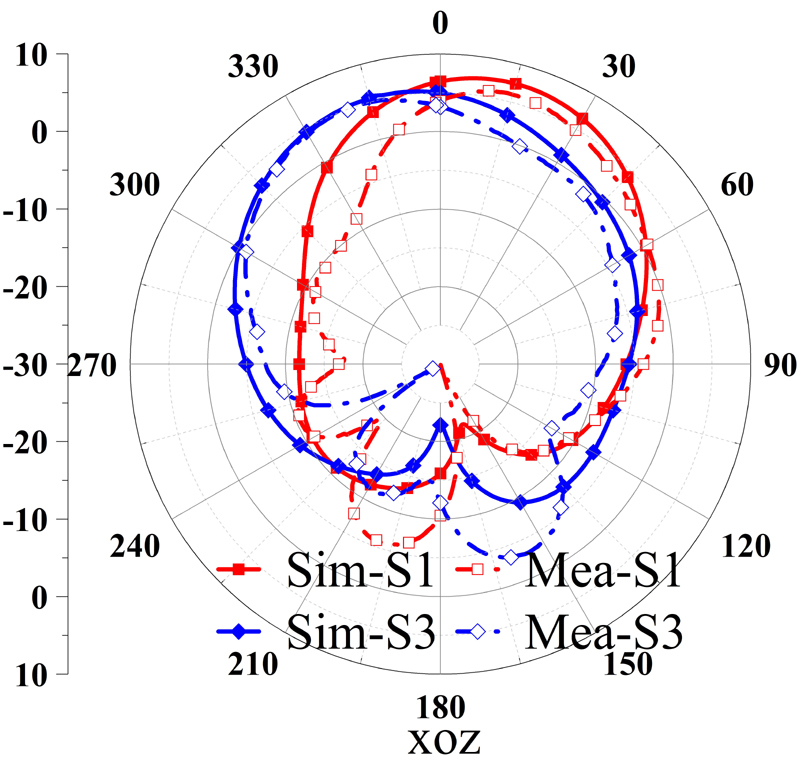
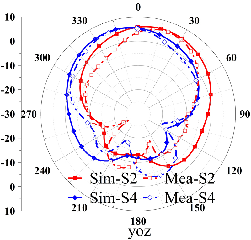
Figure 14: Measured radiation pattern at 5.0 GHz.
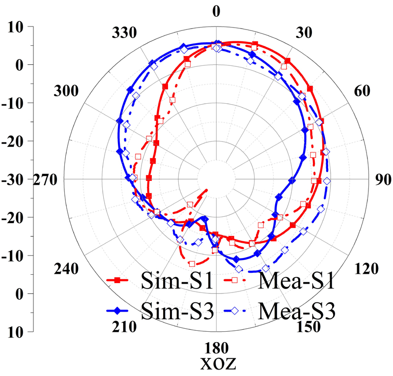
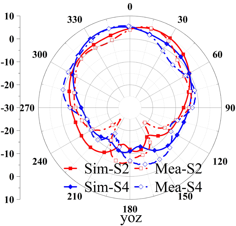
Figure 15: Measured radiation pattern at 5.2 GHz.
The proposed antenna was measured at S1, S2, S3, and S4 states. Measured S is illustrated in Fig. 12 which shows that the antenna has similar bandwidth in these four states, and a common bandwidth of 4.02-5.72 GHz. Radiation patterns of the four states at 4.8, 5, and 5.2 GHz are shown in Figs. 13–15, respectively. As shown in the figures, measurement agrees well with simulation. The proposed antenna achieves pattern reconfiguration both in xoz and yoz planes. Table 3 lists measured peak gains and beams. As shown, the antenna realizes pattern reconfigurations ranging from -16 to 15 in xoz plane, and -13 to 15 in yoz plane. Maximum gain in the working states ranges from 4.94 to 6 dBi.
Table 3: Measured peak beam and peak gain
| 4.8 GHz | 5 GHz | 5.2 GHz | ||||
| Beam (,) | Gain (dBi) | Beam (,) | Gain (dBi) | Beam (,) | Gain (dBi) |
|
| S1 | (15,0) | 5.94 | (14,0) | 5.96 | (16,0) | 5.87 |
| S2 | (15,90) | 5.91 | (15,90) | 5.88 | (16,90) | 5.82 |
| S3 | (-16,0) | 4.94 | (-14,0) | 4.96 | (-15,0) | 5.01 |
| S4 | (-13,90) | 6.00 | (-16,90) | 5.83 | (-14,90) | 5.62 |
Table 4: Comparison of the proposed antenna with published pattern-reconfigurable antennas
| Ref. | BW (GHz) | BW(%) | Size() | Peak Gain(dBi) | Number of PIN Diodes | Number of States | Beam Direction | Beam Range () |
| [9] | 3.54-4.46 | 23 | 31.240.05 | 7.67 | 18 | 5 | 1D | 55 |
| [10] | 2.45-2.45 | 3.8 | 0.450.450.02 | 3.86 | 4 | 2 | N/A | N/A |
| [11] | 2.45-2.45 | 4.0 | 1.720.007 | 7.1 | 8 | 2 | N/A | N/A |
| [13] | 5.5-5.98 | 11.3 | 120.06 | N/A | 2 | 2 | 1D | 50 |
| Pro. | 4.02-5.72 | 34 | 10.950.05 | 4.94-6 | 10 | 12 | 2D | -16-15 in xoz-13-15 in yoz |
Table 4 compares the performance of the antenna proposed in this paper with that of the beam-reconfigurable antennas in the references. As shown, the proposed antenna has virtues of smaller size, wider bandwidth and more tunable states with reconfigurable patterns.
V. CONCLUSION
In this paper we have designed a pattern reconfigurable antenna based on a microstrip-fed patch antenna with full ground plane. A 44 MS is adopted to improve bandwidth as well as realize pattern reconfiguration. Ten of the MS units are loaded with PIN diodes to control the connection/disconnection with the ground plane. DC bias network is arranged outside each MS unit and near its edge to maintain wide bandwidth and obtain good radiation pattern. By controlling each PIN diode’s ON/OFF state, 12 states with different titled patterns are obtained. Antenna fabrication and measurement have been conducted to validate simulations. Measurement shows that the proposed antenna covers impedance bandwidth of 4.02-5.72 GHz and pattern reconfiguration bandwidth of 4.8-5.2 GHz. The antenna works at 12 pattern reconfiguration states ranging from -16 to 15 in xoz and -13 to 15 in yoz plane. The proposed antenna has a small size 10.950.05. With a full ground plane and low profile, the proposed antenna is a good candidate applied in metallic vehicles.
is the free space wavelength at the central operational frequency, Pro.=proposed.
ACKNOWLEDGMENT
This work was supported by the Natural Science Foundation of Shandong Province, China (No. ZR2020MF023).
REFERENCES
[1] Y. X. Cao, S. Yan, J. X. Li, and J. Chen, “A pillbox based dual circularly-polarized millimeter-wave multi-beam antenna for future vehicular radar applications,” IEEE Transactions on Vehicular Technology, vol. 71, no. 7, pp. 7095-7103, July 2022.
[2] L. Y. Wang, H. Y. Shi, X. M. Chen, B. Y. Qu, J. J. Yi, A. X. Zhang, Z. Xu, and H. W. Liu, “Multibeam MS antenna enabled by orbital angular momentum demultiplexing feeding for IoT communication,” IEEE Internet of Things Journal, vol. 10, no. 18, pp. 16169-16182, Sep. 2023.
[3] J. Z. Tang, X. S. Meng, X. M. Chen, R. H. Chen, Y. R. Da, S. T. Zhu, A. X. Zhang, and A. A. Kishk, “Efficient angle calibration method for peak beam measurements in transmitarray-based compact antenna test range,” IEEE Transactions on Electromagnetic Compatibility, 2023.
[4] Y. P. Wang, X. M. Chen, H. L. Pei, W. E. I. Sha, Y. H. Huang, and A. A. Kishk, “MIMO performance enhancement of MIMO arrays using PCS-based near-field optimization technique,” Science China Information Sciences, vol. 66, no. 6, pp. 1-16, June 2023.
[5] Y. S. Li, W. X. Li, and Q. B. Ye, “Miniaturization of asymmetric coplanar strip-fed staircase ultrawideband antenna with reconfigurable notch band,” Microwave and Optical Technology Letters, vol. 55, no. 7, pp. 1467-1470, 2013.
[6] H. Kim, J. Kim, and J. Oh, “Communication a novel systematic design of high-aperture-efficiency 2D beam-scanning liquid-crystal embedded reflectarray antenna for 6G FR3 and radar applications,” IEEE Transactions on Antennas and Propagation, vol. 70, no. 11, pp. 11194-11198, Nov. 2022.
[7] Z. S. Qu, J. R. Kelly, Z. P. Wang, S. Alkaraki, and Y. Gao, “A reconfigurable microstrip patch antenna with switchable liquid-metal ground plane,” IEEE Antennas and Wireless Propagation Letters, vol. 22, no. 5, pp. 1045-1049, May 2023.
[8] J. X. Chen, Y. H. Ke, L. L. Yang, and W. W. Yang, “Pattern-reconfigurable dielectric resonator antenna with endfire beam-scanning feature,” IEEE Antennas and Wireless Propagation Letters, vol. 21, no. 7, pp. 1398-1402, July 2022.
[9] C. J. You, S. H. Liu, J. X. Zhang, X. Wang, Q. Y. Li, G. Q. Yin, and Z. G. Wang “Frequency-and pattern-reconfigurable antenna array with broadband tuning and wide scanning angles,” IEEE Transactions on Antennas and Propagation, vol. 71, no. 6, pp. 5398-5403, June 2023.
[10] G. P. Gao, B. K. Zhang, J. H. Dong, Z. H. Dou, Z. Q. Yu, and B. Hu, “A compact dual-mode pattern-reconfigurable wearable antenna for the 2.4-GHz WBAN application,” IEEE Transactions on Antennas and Propagation, vol. 71, no. 2, pp. 1901-1906, Feb. 2023.
[11] H. Naseri, P. PourMohammadi, N. Melouki, A. Iqbal, and T. A. Denidni, “A low-profile antenna system for generating reconfigurable OAM-carrying beams,” IEEE Antennas and Wireless Propagation Letters, vol. 22, no. 2, pp. 402-406, Feb. 2023.
[12] S. T. Wang, L. Zhu, and H. Deng, “Design approach for pattern-reconfigurable patch antenna without extra feeding networks,” IEEE Transactions on Antennas and Propagation, vol. 71, no. 2, pp. 1925-1930, Feb. 2023.
[13] R. Wang, B. Z. Wang, G. F. Gao, X. Ding, and Z. P. Wang, “Low-profile pattern-reconfigurable vertically polarized endfire antenna with magnetic-current radiators,” IEEE Antennas and Wireless Propagation Letters, vol. 17, no. 5, pp. 829-832, May 2018.
[14] Z. Wang, S. X. Liu, and Y. D. Dong, “Compact wideband pattern reconfigurable antennas inspired by end-fire structure for 5G vehicular communication,” IEEE Transactions on Vehicular Technology, vol. 71, no. 5, pp. 4655-4664, May 2022.
[15] J. F. Li, B. Wu, J. Q. Zhou, K. X. Guo, H. R. Zu, and T. Su, “Frequency and pattern reconfigurable antenna using double layer petal shaped parasitic structure,” IEEE Transactions on Circuits and Systems II: Express Briefs, 2023.
[16] K. D. Hong, X. Zhang, L. Zhu, and T. Yuan, “A high-gain and pattern-reconfigurable patch antenna under operation of TM20 and TM21 modes,” IEEE Open Journal of Antennas and Propagation, vol. 2, pp. 646-653, 2021.
[17] J. A. Liu, Y. F. Cao, and X. Y. Zhang, “A pattern-reconfigurable filtering patch antenna using embedded resonators and switchable elements,” IEEE Transactions on Antennas and Propagation, vol. 70, no. 5, pp. 3828-3833, May 2022.
[18] R. K. Dutta, R. K. Jaiswal, M. Saikia, and K. V. Srivastava, “A two-stage beamforming antenna using butler matrix and reconfigurable frequency selective surface for wide angle beam tilting,” IEEE Antennas and Wireless Propagation Letters, vol. 22, no. 10, pp. 2342-2346, Oct. 2023.
[19] Y. T. Jia, G. S. Jiang, Y. Liu, and Y. C. Zhong, “Beam scanning for dual-polarized antenna with active reflection metasurface,” IEEE Antennas and Wireless Propagation Letters, vol. 21, no. 9, pp. 1722-1726, Sep. 2022.
[20] Z. Wang, and Y. D. Dong, “Metamaterial-based, vertically polarized, miniaturized beam-steering antenna for reconfigurable sub-6 GHz applications,” IEEE Antennas and Wireless Propagation Letters, vol. 21, no. 11, pp. 2239-2243, Nov. 2022.
[21] S. N. Zhao, Z. Wang, and Y. D. Dong, “Pattern-reconfigurable antenna using low-profile electric and magnetic radiators,” IEEE Antennas and Wireless Propagation Letters, vol. 22, no. 3, pp. 616-620, Mar. 2023.
[22] W. M. Abdulkawi, A. A. Sheta, W. A. Malik, S. U. Rehman, and M. S. Alkanhal, “RF MEMS switches enabled H-shaped beam reconfigurable antenna,” Applied Computational Electromagnetics Society Journal, vol. 34, no. 09, pp. 1312–1319, Sep. 2019.
[23] Y. Zhang, D. Sun, T. Dong, and J. Yin, “Design of reconfigurable patch antenna in frequency, pattern, and switchable polarization,” Applied Computational Electromagnetics Society Journal, vol. 35, no. 9, pp. 1037–1046, Sep. 2020.
[24] T. Shi, R. L. Chai, X. M. Chen, M. Li, T. Zhang, and M. C. Tang, “A low-profile, circularly polarized, metasurface-based antenna with enhanced bandwidth and stable high gain,” IEEE Antennas and Wireless Propagation Letters, vol. 22, no. 2, pp. 253-257, Aug. 2022.
[25] K. E. Kedze, H. Wang, and I. Park, “A metasurface-based wide-bandwidth and high-gain circularly polarized patch antenna,” IEEE Transactions on Antennas and Propagation, vol. 70, no. 1, pp. 732-737, Jan. 2022.
[26] H. H. Tran, C. D. Bui, N. Nguten-Trong, and T. K. Nguyen, “A wideband non-uniform metasurface-based circularly polarized reconfigurable antenna,” IEEE Access, vol. 9, pp. 42325-42332, Mar. 2021.
[27] Y. S. Li, W. X. Li, and W. H. Yu, “A switchable UWB slot antenna using SIS-HSIR and SIS-SIR for multi-mode wireless communications applications,” Applied Computational Electromagnetics Society Journal, vol. 27, no. 4, pp. 340-351, Apr. 2012.
[28] J. F. Jiang, Y. F. Xia, and Y. S. Li, “High isolated X-band MIMO array using novel wheel-like metamaterial decoupling structure,” Applied Computational Electromagnetics Society Journal, vol. 34, no. 12, pp. 1829-1836, Dec. 2019.
[29] S. Y. Luo, Y. S. Li, Y. F. Xia, G. H. Yang, L. J. Sun, and L. Zhao, “Mutual coupling reduction of a dual-band antenna array using dual-frequency metamaterial structure,” Applied Computational Electromagnetics Society Journal, vol. 34, no. 3, pp. 403-410, Mar. 2019.
[30] T. Sabapathy, M. F. Jamlos, R. B. Ahmad, M. Jusoh, and M. I. Jais, “A reconfigurable microstrip rectangular parasitic array antenna,” 2013 IEEE Symposium on Wireless Technology & Applications, Kuching, Malaysia, Sep. 2013.
[31] A. Meredov, K. Klionovski, and A. Shamim, “Screen-printed, flexible, parasitic beam-switching millimeter-wave antenna array for wearable applications,” IEEE Open Journal of Antennas and Propagation, vol. 1, pp. 2-10, 2020.
[32] Q. Q. Liu, Z. K. Geng, R. Zhao, S. D. Li, Z. Yao, and W. H. Zong, “A wideband planar pattern reconfigurable antenna for IEEE 802.11 ac WLAN applications” International Journal of RF and Microwave Computer-Aided Engineering, vol. 32, no. 10, pp. 23323, July 2022.
BIOGRAPHIES

GuangRui Liu was born in Qingdao, Shandong, Province, China, in 1997. In 2020, he received the B.S. degree in communication engineering from Changsha University of Science & Technology, Changsha, Hunan, Province, China. He is currently pursuing the M.S. degree in new-generation electronic information technology at Qingdao University, Qingdao, China. His current research interests include broadband antennas and reconfigurable antennas.

Cheng Ju received the Ph.D. degree from Beijing University of Posts and Telecommunications in 2015. He joined the School of Electronic Information at Qingdao University in 2017 as a lecturer. He is mainly engaged in researching DSP algorithms for space laser communication systems and FPGA implementation of DSP algorithms.

Zijie Lireceived the B.S. degree in Electromagnetic Field and Wireless Technology from the Nanjing University of Posts and Telecommunications, Nanjing, China, in 2021. He is currently pursuing the M.S. degree with the school of electronic information, Qingdao University, Qingdao, China. His current research interests include circularly polarized antennas, metamaterial-based antennas, and reconfigurable antennas.

Zhiqun Yang received the Ph.D. degree in communication and information system from Nanjing University of Technology, Nanjing, Jiangsu Province, China, in 2003. He is with Shandong Institute of Space Electronic Technology, China Aerospace Science and Technology Corporation, Yantai, China, as a Senior Engineer. His research interest is signal processing and communication.

Xiaoyun Qu was born in Yantai City, Shandong Province, China, in 1974. She received the B.S. in applied mathematics from Yantai University, in 1996, M.S. degree in electromagnetic fields and microwave technology from Nanjing Electronics research Center, Nanjing, Jiangsu Province, China, in 1990. She is with Shandong Institute of Space Electronic Technology, Yantai, China, as a Senior Engineer. Her research interest is antenna design.

Na Liu received the Ph.D. degree from Beijing University of Posts and Telecommunications in 2015. She joined the School of Electronic Information at Qingdao University in 2018 as a lecturer. She is mainly engaged in researching DSP algorithms for coherent detection systems.

Wei-hua Zong was born in Penglai City, Shandong Province, China, in 1975. She received the B.S. in applied mathematics from Yantai University, in 1997, M.S. degree in electromagnetic fields and microwave technology from Nanjing Electronics research Center, Nanjing, Jiangsu Province, China, in 2000, and the Ph.D. degree in electromagnetic fields and microwave technology from Xidian University, Xian, Shanxi Province, China, in 2004. In 2004, she joined Qingdao University, Qingdao, Shandong Province, China, as a lecture. Since 2005, she has been an Associate Professor in Qingdao University. From February to August 2010, she was a Visiting Scholar Assistant with Electrical and Computation Engineering Department, National University of Singapore. Her research interests include antenna design and electromagnetic material measurement.
ACES JOURNAL, Vol. 39, No. 10, 868–875
doi: 10.13052/2024.ACES.J.391004
© 2024 River Publishers