Bandwidth and Gain Improvement of a Circularly Polarized Slot Antenna Using Nonuniform Metasurface
Qiang Chen, Jun Yang, Changhui He, Liang Hong, Tianci Yan, Fangli Yu, Di Zhang, and Min Huang
Air Force Early Warning Academy
Wuhan, Hubei 430019, China
1062620145@qq.com, yangjem@126.com, 513442678@qq.com, 197222036@qq.com, 84802610@qq.com, yufangli_aewa@163.com, deeafeu@163.com, huangmin_hm@163.com
Submitted On: December 7, 2023; Accepted On: October 10, 2024
ABSTRACT
This paper presents a novel design of a circularly polarized antenna based on a nonuniform metasurface (NMS). The original antenna comprises a uniform metasurface (UMS) layer and a slot antenna below. In order to achieve circularly polarized (CP) radiation, an oblique slot is etched on the center patch, and the size ratio between the center patch and the surrounding patches is adjusted to create the NMS. To further enhance the CP properties, an improved NMS (INMS) is proposed, consisting of four units with corners removed, building upon the original NMS design. Simulation results demonstrate that the proposed antenna design offers an S11 bandwidth ranging from 4.39 to 7.21 GHz, with a 3 dB axial ratio (AR) bandwidth spanning from 5.43 GHz to 6.76 GHz. Compared to the original UMS-based antenna, the INMS design shows an average gain increase of 1.21 dB, with a peak gain of 9.49 dBic. Furthermore, utilizing characteristic mode analysis (CMA), this paper explores the modal behaviors when applying the NMS to the antenna. The results indicate that this configuration excites two orthogonal modes, leading to CP radiation and the emergence of an additional AR minimum point. These factors contribute to the broader bandwidth observed in the proposed antenna design. The outstanding radiation performance of the proposed antenna design makes it suitable for various applications, including military and civilian communication, as well as point-to-point links.
Index Terms: Characteristic mode analysis, circularly polarized, low profile, nonuniform metasurface.
I. INTRODUCTION
Circularly polarized (CP) antennas are essential for wireless communication systems and point-to-point links due to their ability to mitigate multi-path effects and polarization mismatch. The growing demand for CP antennas that offer high gain, wideband coverage, and a wide 3 dB axial ratio (AR) angle has prompted the exploration of different design techniques. One such technique is the use of metasurface, which have proven to be highly effective in generating and enhancing CP radiation. Consequently, a significant number of antennas based on metasurface have been developed and wideband CP properties successfully demonstrated [1–8].
A nonuniform metasurface (NMS) was employed in a 22 CP antenna array arrangement, as explored in a separate study [9]. The design incorporated a Wilkinson power divider feed network, showcasing remarkable bandwidth capabilities. Specifically, it achieved an impressive 3 dB axial ratio bandwidth (ARBW) of 33.13% (7-9.78 GHz) and a wide instantaneous bandwidth (IBW) of 49.6% (6.05-10.04 GHz). This investigation effectively highlighted the potential of utilizing NMS configurations to enhance the radiation properties of CP antennas.
In a separate investigation [9], researchers explored the use of an NMS in a 22 CP antenna array. The design incorporated a Wilkinson power divider feed network and demonstrated impressive bandwidth capabilities. It achieved an instantaneous bandwidth (IBW) of 49.6% (6.05-10.04 GHz) and a 3 dB ARBW of 33.13% (7-9.78 GHz). These results effectively showcased the potential of NMS arrangements in enhancing the radiation properties of CP antennas. This study’s findings have significant implications for advancing the development of high-performance antennas in wireless communication applications. By utilizing NMS, antenna designs can support wider frequency ranges and improved polarization properties, leading to enhanced performance in wireless communication systems. This research contributes to the exploration of innovative approaches to optimize antenna performance and increase the efficiency of wireless communication systems.
It should be noted that previous works [4–9] did not take into account the gain and 3 dB AR beamwidth. Moreover, the bandwidths of metasurface-based antennas were found to be limited. To address theselimitations, an NMS design can be utilized to precisely control the distribution of the electromagnetic field. This approach enables the antenna to enhance its radiation properties, achieving high gain and wide bandwidth. By ensuring the antenna radiates with the desired polarization, remarkable radiation properties can be achieved. This research contributes to the exploration of innovative approaches to optimize antenna performance and increase the efficiency of wireless communication systems.
This paper presents an innovative NMS design that combines the central patches of 22 corner-cut slotted patches with the surrounding corner-cut patches. Extensive simulations and precise measurements are conducted to validate the effectiveness of this design, showing remarkable agreement. Moreover, the paper utilized characteristic mode analysis (CMA) to analyze the radiated performance, which is in accordance with the simulated and measured results.
II. EVOLUTION DESIGN OF THE NONUNIFORM METASURFACE ELEMENT
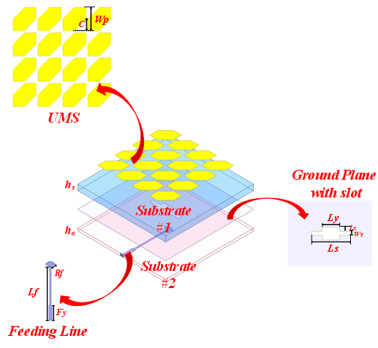
Figure 1: Antenna configuration: Perspective view in 3D, UMS, feeding line and ground plane with slot.
In the design process, the antenna with UMS is proposed. The UMS-based antenna’s geometric dimensions are shown in Fig. 1, consisting of two layers of dielectric substrates, two layers of metal coatings and a feeding line. The layers in order from top to bottom are the UMS layer, dielectric substrate #1, ground plane with slot, dielectric substrate #2 and feeding line. Dielectric substrates #1 and #2 are made of the same material (Duroid) and sized 5555 mm, with electromagnetic parameters 2.2 and 0.0009. The heights of substrates #1 and #2 are denoted as h and h, respectively. The UMS layer consists of a 44 array of corner-cut square patch, with asymmetric structure for circular polarization radiation. The metal ground of dielectric substrate #2 is etched with a regular rectangular notched slot, and the specific dimensional parameters are shown in Table 1. Both layers of dielectric substrates are of the same size. The feeding line is positioned on each side of the slot in the dielectric substrate. During the radiation process of the antenna, microwave energy is initially transferred to the UMS layer through the regular rectangular slot, and the UMS is then utilized for amplitude and phase modulation of electromagnetic waves, resulting in the conversion from linear polarization to circular polarization.
Table 1: Optimal variable of proposed INMS-based antenna
| Dimension | Size (mm) | Dimension | Size (mm) |
| L | 55 | W | 12.5 |
| T | 2 | C | 6 |
| T | 9 | C | 5 |
| W | 10 | W | 2 |
| L | 2 | L | 18 |
| L | 4 | R | 3 |
| L | 28 | F | 0.5 |
| C | 6 | h | 3.5 |
| h | 1.5 |
As demonstrated by the simulated results depicted in Fig. 2 by Ansys HFSS, the S11 less than -10 dB ranges from 4.77 GHz to 6.43 GHz, 6.75 GHz to 8.45 GHz and 9.08 GHz to 9.59 GHz, which meets the requirements for the antenna’s external radiation. At 6.12 GHz, the antenna achieves a peak gain of 8.99 dB. Within the frequency range of 5.95-6.25 GHz, AR falls below the 3 dB line, enabling CP radiation. However, due to the limitations of the UMS structure in controlling electromagnetic wavefronts, the UMS-based antenna’s performance is relatively poor. The reflection coefficient bandwidth is discontinuous, the AR bandwidth is narrow and the circular polarization effect is not satisfactory, making it difficult to meet the requirements of broadband design.
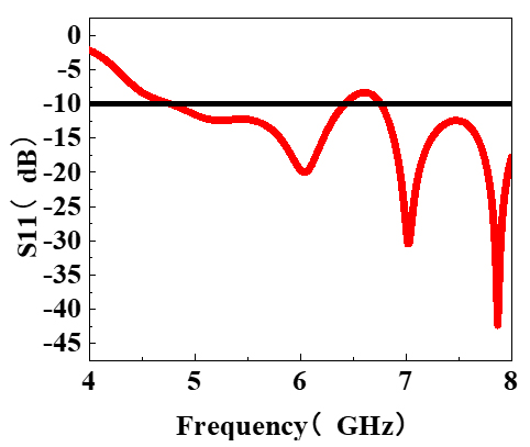
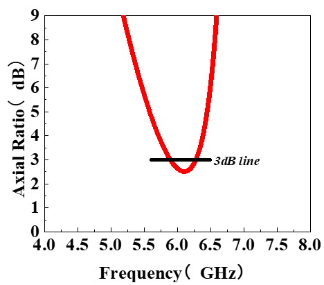
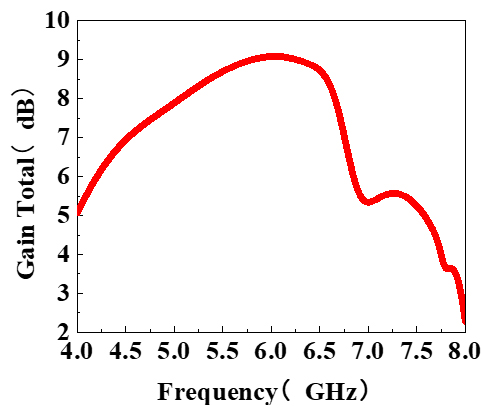
Figure 2: Simulations of the UMS-based antenna: (a) S11, (b) Axial Ratio, and (c) Gain Total.
Hence, to further improve the antenna’s circular polarization radiation performance, NMS should be employed. As Fig. 3 depicts, the next step involves etching 45 angled rectangular slots on the central 22 corner-cut square patches, which aims to increase the capability for linear-to-circular polarization conversion. With the right-angled slot tilted at 45 on the upper right side, the antenna’s CP radiation was facilitated. Through simulation analysis with Ansys HFSS, it was found that when the length of the angled slot is 9 mm and the width is 2 mm, the antenna exhibits improved AR bandwidth and S11 bandwidth.
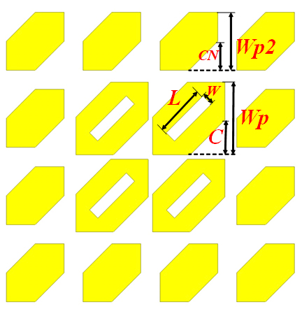
Figure 3: Configuration of the NMS.
The NMS-based antenna was simulated in HFSS, and the results are plotted in Fig. 4. The results show that the proposed design achieves a S11 bandwidth of 2.72 GHz, which ranges from 4.39 GHz to 7.11 GHz and a 3 dB AR bandwidth of 0.97 GHz, which ranges from 5.47 GHz to 6.44 GHz, with the minimum value below 1 dB. The simulated results have successfully proven NMS’s capability of improving the radiation performance of the antenna. Compared to the UMS-based design, the radiation performance and circular polarization properties of the antenna were greatly enhanced.
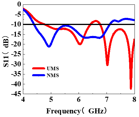
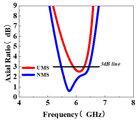
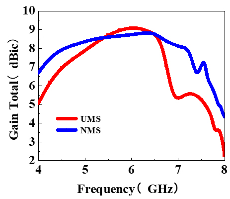
Figure 4: Simulation of NMS-based antenna: (a) S11, (b) Axial Ratio, and (c) Gain Total.
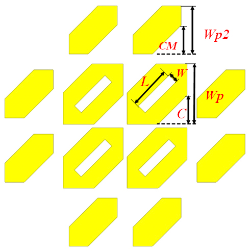
Figure 5: Configuration of the improved NMS.
It can be observed that the S11 bandwidth is 2.76 GHz, ranging from 4.39 GHz to 7.15 GHz, which has been broadened as a result of the corner cut on the NMS. This design modification effectively enhances the material’s performance by reducing reflections and improving impedance matching, leading to more efficient energy transmission. Additionally, the AR bandwidth has significantly improved, totaling 1.33 GHz and ranging from 5.43 to 6.76 GHz. This enhancement is crucial for applications that require circular polarization, as a lower AR signifies better polarization retention. Together, these improvements indicate that the modified NMS design is well-suited for advanced communication systems and radar applications, where signal integrity across a wide frequency range is essential.
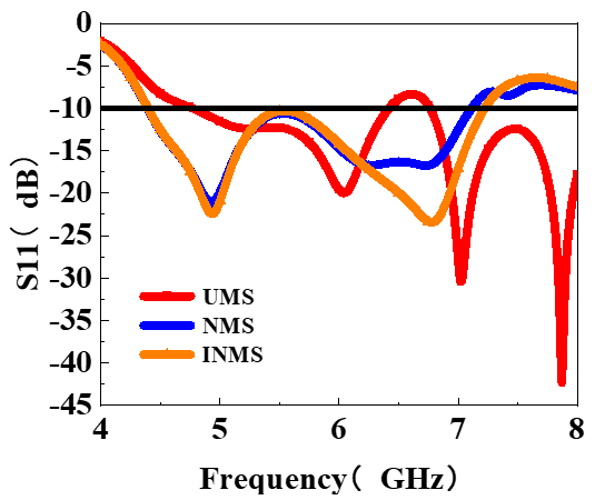
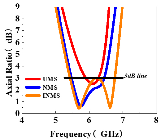
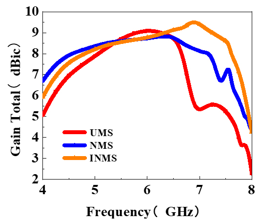
Figure 6: Simulation of the INMS-based antenna: (a) S11, (b) Axial Ratio, and (c) Gain Total.
In addition, the normalized radiation patterns in the far-field at 4.7 GHz display remarkably minimal cross-polarizations and a negligible back lobe in both the xoz and yoz planes, as depicted in Fig. 7. The radiation pattern of the improved NMS (INMS)-based antenna is stable and essentially symmetric, with a much lower level of cross-polarization than co-polarization. Within the CP operating bandwidth in two orthogonal planes, the designed antenna demonstrates excellent wideband LHCP radiation properties, with cross-polarization levels below -30 dB and back lobe level below -10 dB, resulting in effective forward radiation and enhanced directivity. Thus, the INMS-based antenna demonstrates fair CP radiation properties.
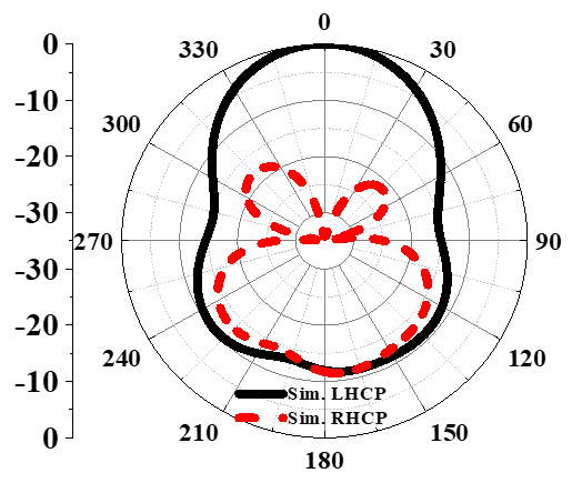
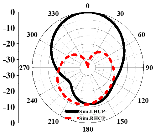
Figure 7: Simulated radiation pattern in the (a) xoz plane and (b) yoz plane at 5.7 GHz.
III. ANALYSIS OF MODE BEHAVIORS OF THE NONUNIFORM METASURFACE ELEMENT USING CMA
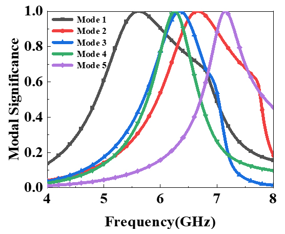
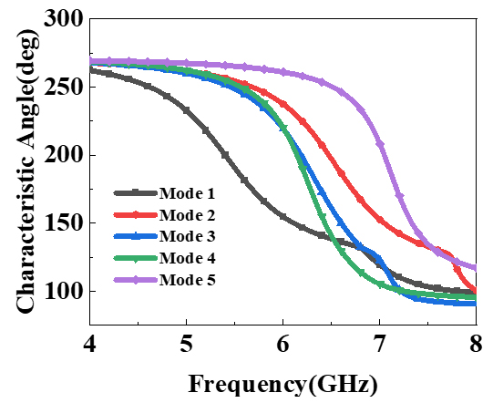
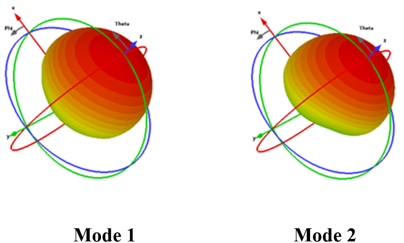
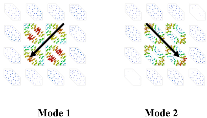
Figure 8: Mode behaviors of NMS-based antenna: (a) MS values, (b) CAs, (c) radiation pattern at 6 GHz of mode 1 and mode 2, and (d) surface currents.
The NMS design’s radiation performance was further elucidated by employing CMA to enhance the antenna’s properties. This was achieved by calculating the inherent properties of the conductor structure without the addition of excitation. Of particular note is that various parameters derived through CMA can be used to analyze whether an antenna can generate CP radiation. To generate the corresponding CP radiation, it is necessary to excite two orthogonal modes simultaneously during CMA and satisfy the following five prerequisites: (1) MS values of the two modes should be relatively large and both greater than 0.707; (2) MS values of the two modes should be close; (3) phases of the two modes should have an approximate phase difference of 90 degrees; (4) current surface performed by the two modes should be directed orthogonally; and (5) maximum radiation directions of the two modes should be aligned. MS values, CA, surface currents and radiation patterns were further examined utilizing the multilayer solver in CST2022.
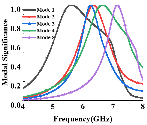
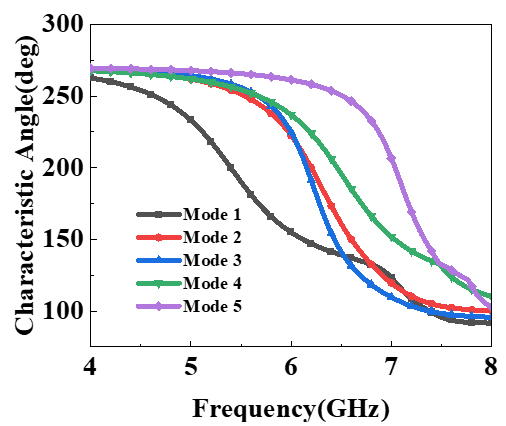
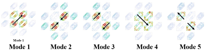
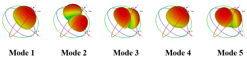
Figure 9: Modal behaviors of proposed INMS: (a) MS values, (b) CAs, (c) surface currents, and (d) radiation pattern at 6 GHz for the first five modes.
For NMS, the MS values and the CAs of mode 1 and mode 2 were calculated as illustrated in Fig. 8. Mode 1 and mode 2 are resonant at 5.61 GHz and 6.66 GHz, respectively, and the phase difference of the two modes CAs are about 90 degrees, with their corresponding frequency points falling within the covered resonance band, which indicates that the two modes can be seen as a pair of potentially orthogonal modes. To further explore whether it can achieve circular polarization or not, the surface currents and the broadside radiation pattern of modes 1 and 2 are depicted in Fig. 8. The surface current of mode 1 distributes mainly along the diagonal direction from up right to down left, while mode 2 distributes in a perpendicular direction. In the meantime, the far-field radiation patterns of mode 1 and mode 2 had a similar broadside orientation, aligned with the z-axis, which means that the NMS-based antenna can realize wideband CP radiation.
In addition, the modal behaviors of INMS were also investigated in the design process in order to attain enhanced properties. As the results showed in Fig. 9, the first five modal behaviors of INMS were simulated, which indicates that the INMS resonates at 5.61, 6.35, 6.25, 6.65 and 7.13 GHz, corresponding to the MS values that reach to 1. It is obvious that mode 1 and mode 4 should be chosen as the operation modes because their bandwidth, which is greater than 0.707, falls within the operating band. By analyzing the simulated results, it is further found that the CAs of the mode 1 and mode 4 maintain a 90 degrees phase difference, which indicates the potential to achieve CP properties. The surface current and radiation pattern are also investigated, as depicted in Fig. 9. Obviously, for mode 1, the maximum current directs from down left to up right, while the surface current of mode 4 is along the diagonal direction, while other modes were found to have an anomalous current. It can be also observed that mode 1 and mode 4 share a similar radiation pattern along the z-axis. Therefore, we can deduce that mode 1 and mode 4 are a set of orthogonal modes capable of achieving CP properties.
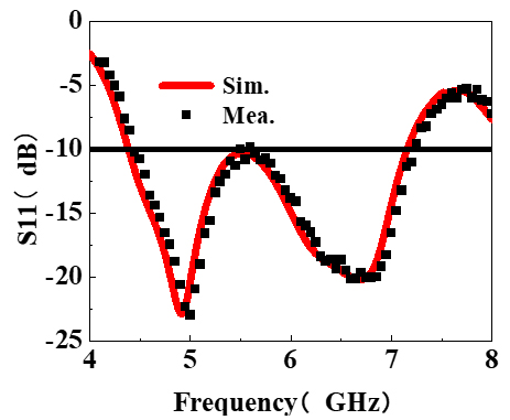
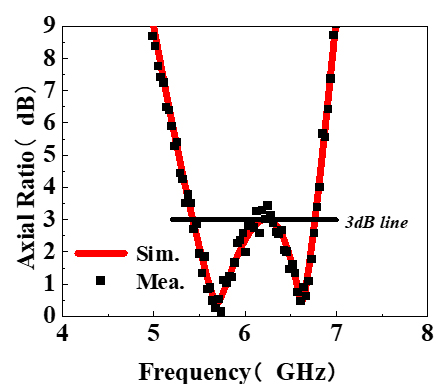
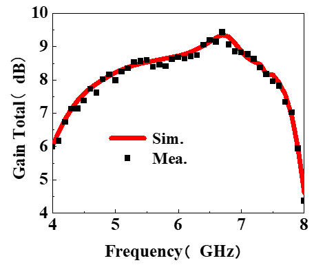
Figure 10: Simulated and measured results of INMS MS-based antenna: (a) S11, (b) Axial Ratio, and (c) Gain Total within the main lobe.
Table 2: Performance comparison of the recently reported CP antennas
| Ref. | Size () | 3 dB AR BW (GHz) | Peak Gain (dBic) | 3dB AR Angle Range | Operating Bandwidth (GHz) |
| Proposed | 110.1 | 5.43-6.76 | 9.35 | -52 to 42 | 4.39-7.15 |
| [9] | 220.08 | 7-9.78 | 13.17 | null | 6.05-10.04 |
| [10] | 0.670.670.06 | 1.3-2.1 | 8.7 | null | 1.4-2.1 |
| [11] | 2.62.630.36 | 9.8-10.2 | 13.4 | -10 to 10 | 9.86-10.14 |
| [12] | 2.02.00.6 | 7.3-7.6 | 15.1 | null | 7.3-7.6 |
| [13] | 2.02.00.88 | 4.12-6.39 | 14.5 | 3.82-6.01 | |
| [14] | 330.19 | 9.7-10.3 | 17.8 | -15 to 15 | 9.8-10.2 |
IV. RESULTS OF SIMULATED AND MEASURED
To assess the performance of the proposed INMS-based antenna, simulations were conducted in HFSS. Additionally, measurements were carried out in an anechoic chamber using a vector network analyzer to validate the accuracy of the design.
The results, depicted in Fig. 10 (a), showcased the S11 bandwidth below -10 dB of 2.76 GHz, ranging from 4.39 GHz to 7.15 GHz. Although there were slight disparities between the simulated and measured frequencies, they fell within an acceptable range. The designed antenna exhibited a measured AR bandwidth of 1.33 GHz, ranging from 5.43 GHz to 6.76 GHz, closely aligning with the simulation results, shown an Fig. 10 (b). Remarkably, all frequencies remained within the operating band, demonstrating exceptional radiation performance across a wide frequency range. Figure 10 (b) provides further evidence of the design’s effectiveness, as the AR values remained consistently flat at a low level of averagely 1.89 dB throughout the operating band. Furthermore, as depicted in Fig. 10 (c), the maximum gain measured in the main lobe reached 9.35 dB at 6.72 GHz, falling within the operating band covered by the 3 dB AR bands. This outstanding performance signifies the antenna’s capability in terms of CP radiation. Additionally, the gain values exhibited stability and consistency across the operated bands, resulting in a flat response.
In Fig. 11, the radiation pattern at 5.7 GHz was analyzed. It was found that the antenna demonstrated a low cross-polarization level of less than -30 dB in both the xoz and yoz planes, indicating successful CP radiation. Furthermore, the side lobe values were at least 10 dB lower than those of the main lobe, suggesting an excellent radiation performance.
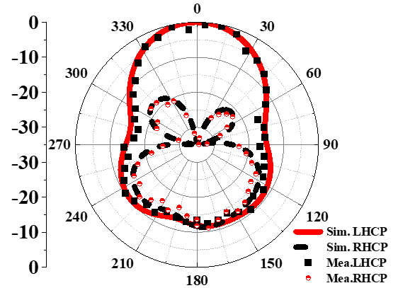
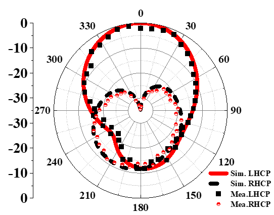
Figure 11: Simulated and measured radiation patterns at 5.7 GHz in the (a) xoz plane and (b) yoz plane.
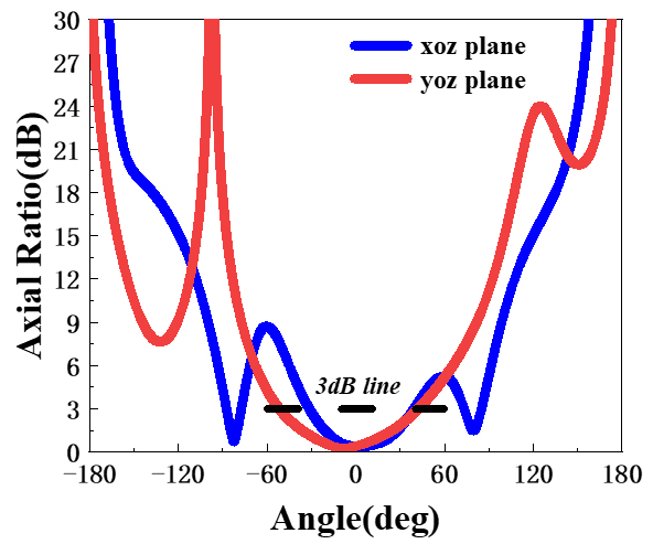
Figure 12: Simulated Axial Ratio values versus angle in the xoz and yoz planes at 5.7 GHz.
Figure 12 presents AR versus angle at 5.7 GHz. The yoz plane exhibited a wide-angle range of CP property, with ARs that were lower than 3 dB exhibiting a beamwidth of 94, ranging from to , while performance in the xoz plane was 71, ranging from to , achieving a satisfactory CP property. To further validate the effectiveness of the proposed design, a comprehensive comparison was made with other recently proposed metasurface-based antennas, as listed in Table 2. The results clearly demonstrate that the proposed antenna outperforms its counterparts in terms of radiation properties. Remarkably, this superior performance is achieved within a compact size of 10100.10, making it highly desirable for various applications. In conclusion, the analysis of the radiation pattern and AR, along with the comparison with other antennas, highlight the exceptional radiation characteristics and compact size of the proposed antenna design. These findings further validate its effectiveness and underscore its potential for a wide range of applications.
V. CONCLUSION
Proposed in this research paper is a novel circularly polarized antenna design that incorporates a nonuniform metasurface. The principal element of this antenna is a UMS layer, which is composed of an arrangement of 44 corner-cut patches and a slot antenna located below. To bolster CP radiation, the NMS was introduced into the design of the antenna, which consists of a 22 arrangement of central corner-cut slotted patches and the surrounding corner-cut patches. Through extensive simulations, the proposed antenna’s remarkable radiation properties are confirmed. By utilizing CMA, the radiation performance of INMS is further analyzed. Based on the CMA results, the INMS exhibits a broader CP band than the UMS due to its ability to satisfy a broader frequency range of MS and CA. Beyond its exceptional radiation properties, the proposed antenna exhibits potential for employment in communication andpoint-to-point links systems. This research contributes significantly to the progression and refinement of CP antenna design.
ACKNOWLEDGEMENT
This work was supported by the Natural Science Foundation of Hubei Province under Grant 2023AFB452.
REFERENCES
[1] K. Li, Y. Liu, Y. Jia, and Y. J. Guo, “A circularly polarized high gain antenna with low RCS over a wideband using chessboard polarization conversion metasurfaces,” IEEE Trans. Antennas Propag., vol. 65, no. 8, pp. 4288-4292, 2017.
[2] Y. Huang, L. Yang, J. Li, Y. Wang, and G. Wen, “Polarization conversion of metasurface for the application of wide band low-profile circular polarization slot antenna,” Appl. Phys. Lett., vol. 109, no. 5, p. 054101, 2016.
[3] Z. G. Liu, Z. X. Cao, and L. N. Wu, “Compact low-profile circularly polarized Fabry-Perot resonator antenna fed by linearly microstrip patch,” IEEE Antennas Wirel. Propag. Lett., vol. 16, pp. 524-527, 2016.
[4] Z. Wu, L. Li, Y. Li, and X. Chen, “Metasurface superstrate antenna with wideband circular polarization for satellite communication application,” IEEE Antennas Wireless Propag. Lett., vol. 10, pp. 907-910, 2015.
[5] H. L. Zhu, S. W. Cheung, K. L. Chung, and T. I. Yuk, “Linear-to-circular polarization conversion using metasurface,” IEEE Trans. Antennas Propag., vol. 61, no. 9, pp. 4615-4623, 2013.
[6] Q. Chen and H. Zhang, “Dual-patch polarization conversion metasurface-based wideband circular polarization slot antenna,” IEEE Access, vol. 6, pp. 74772-74777, 2018.
[7] P. Xie, G. Wang, H. Li, and J. Liang, “A dual-polarized two-dimensional beam-steering Fabry-Perot cavity antenna with a reconfigurable partially reflecting surface,” IEEE Antennas Wireless Propag. Lett., vol. 16, pp. 2370-2374,2017.
[8] Q. Chen and H. Zhang, “High-gain circularly polarized Fabry-Pérot patch array antenna with wideband low-radar-cross-section property,” IEEE Access, vol. 7, pp. 8885-8889, 2019.
[9] X. Gao, S. Yin, G. Wang, C. Xue, and X. Xie, “Broadband low-RCS circularly polarized antenna realized by nonuniform metasurface,” IEEE Antennas Wireless Propag. Lett., vol. 21, no. 12, pp. 2417-2421, 2022.
[10] J. Cui, X. Zhao, and W. Sheng, “Low profile and broadband circularly polarized metasurface antenna based on nonuniform array,” AEU-International Journal of Electronics and Communications, vol. 156, p. 154386, 2022.
[11] N. Hussain, S. I. Naqvi, W. A. Awan, and T. T. Le, “A metasurface-based wideband bidirectional same sense circularly polarized antenna,” Int. J. RF Microw. Comput. Aided Eng., vol. 30, p. 22262, 2020.
[12] Y. Cheng and Y. Dong, “Bandwidth enhanced circularly polarized Fabry-Perot cavity antenna using metal strips,” IEEE Access, vol. 8, pp. 60189-60198, 2020.
[13] F. Qin, S. Gao, G. Y. Wei, Q. Luo, C. Mao, C. Gu, J. Xu, and J. Li, “Wideband circularly polarized Fabry-Perot antenna [antenna applications corner],” IEEE Antennas and Propagation Magazine, vol. 57, no. 5, pp. 127-135, 2015.
[14] N. Hussain, M. Jeong, J. Park, and N. Kim, “A broadband circularly polarized Fabry-Perot resonant antenna using a single-layered PRS for 5G MIMO applications,” IEEE Access, vol. 7, pp. 42897-42907, 2019.
BIOGRAPHIES

Qiang Chen was born in Jiangxi, China. He received the master’s and Ph.D. degree from Air Force Engineering University (AFEU), Xi’an, China, in 2015 and 2019, respectively. He is currently a lecturer with Air Force Early Warning Academy, Wuhan, Hubei, China. His research interests include microwave circuits, antennas and arrays.

Jun Yang was born in 1973. He received his Ph.D. degree from Air Force Engineering University, Xian, China, in 2003. Currently, he is an associate professor at the Air Force Early Warning Academy, Wuhan, China. His research interests cover radar systems, radar imaging and compressed sensing.

Changhui He was born in 1973. She received the master’s degree from Central China Normal University. She is currently an associate professor at Air Force Early Warning Institute. She is interested in electromagnetic field, microwave technology, and antenna design. Ms He has published over 20 technical papers and authored one book. She holds four national invention patents.

Liang Hong was born in Wuhan, China. He received the B.S. and M.S. degrees from Huazhong University of Science and Technology, Wuhan, China, in 2005 and 2011, respectively. His research interests include microwave devices and microwave technology.

Tianci Yan was born in Hubei, China. He received the B.S. from Air Force Early Warning Academy, Wuhan, China, in 2023. His research interests include microwave devices and microwave technology.

Fangli Yu was born in China, in 1983. He received the B.E. degree from the Air Force Early Warning Academy, Wuhan, China. He is currently a Ph.D. Candidate in the School of Information and Engineering, Wuhan University of Technology. His current research interest is radar signal processing.

Di Zhang received the B.S., M.S. and Ph.D. degrees from Air Force Engineering University (AFEU), Xi’an, China, in 2013, 2015, and 2019, respectively. He is currently a lecturer with Air Force Early Warning Academy. His research interests include RF orbital angular momentum antennas, reflect array antennas and metasurface.

Min Huang graduated from Taiyuan University of Technology with a master’s degree in physical electronics. She is now an instructor at the Air Force Early Warning Academy. Her research interests are electromagnetic fields and microwave technology.
ACES JOURNAL, Vol. 39, No. 9, 786–793
doi: 10.13052/2024.ACES.J.390904
© 2024 River Publishers